Q I G Quick Installation Guide
PRINTED ON RECYCLED PAPER
Version 2.1
Quick Installation Guide
Resetting
To restore the switch configurations back to the factory defaults, press the Reset button more than 5
seconds.
To reboot the switch, press the Reset button less than 5 seconds.
Specifications
Configurations
After installing the switch, the green power LED should turn on. Please refer to the
following tablet for LED indication.
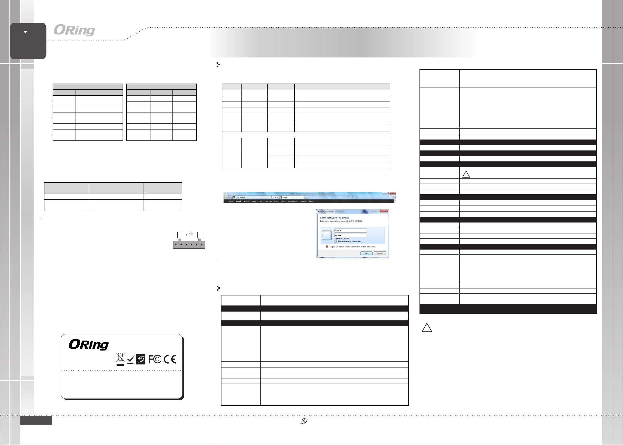
1. Launch the Internet Explorer and type in IP address of the switch. The default static IP address is
192.168.10.1
2. Log in with default user name and password
(both are admin). After logging in, you should
see the following screen. For more information
on configurations, please refer to the user
manual. For information on operating the switch
using ORing’s Open-Vision management utility,
please go to ORing website.
Follow the steps to set up the switch:
PWR Green On DC power on
PWR1 Green On DC power module 1 activated
PWR2 Green On DC power module 2 activated
R.M Green On Ring Master
Ring Green
On Ring enabled
Blinking Ring structure is broken (i.e. part of the ring is disconnected)
Fault Amber On Faulty relay (power failure or port disconnected)
10/100Base-T(X) Ethernet ports
LNK/ACT
with speed
Green
On Port link up
Blinking Data transmitted
Amber
On Full-duplex mode
Off Half-duplex mode
Blinking Half-duplex mode and collision occurred
For pin assignments for different types of cables, please refer to the following
tables.
10/100 Base-T(X) MDI/MDI-X
Pin Number MDI port MDI-X port
1 TD+(transmit) RD+(receive)
2 TD-(transmit) RD-(receive)
3 RD+(receive) TD+(transmit)
4 Not used Not used
5 Not used Not used
6 RD-(receive) TD-(transmit)
7 Not used Not used
8 Not used Not used
Note: “+” and “-” signs represent the polarity of the wires that make up each
wire pair.
To connect the console port to an external management device, you need an RJ-45 to
DB-9 cable, which is also supplied in the package. Below is the console port pin
assignment information.
Console Port Pin Definition
PC (male) pin assignment RS-232 with DB9 (female) pin
assignment (RJ45-DB9 cable) RJ45 pin assignment
PIN#2 RxD PIN#2 RxD PIN#2 RxD
PIN#3 TxD PIN#3 TxD PIN#3 TxD
PIN#5 GND PIN#5 GND PIN#5 GND
Wiring
STEP 1: Insert the negative/positive wires into the V-/V+ terminals,
respectively.
The switch supports dual redundant power supplies, Power Supply1
(PWR1) and Power Supply 2 (PWR2). The connections for PWR1,
PWR2 and the RELAY are located on the terminal block.
STEP 2: To keep the DC wires from pulling loose, use a small flat-
blade screwdriver to tighten the wire-clamp screws on the front of the
terminal block connector.
PWR-1PWR-2
1A@24V
V2- V2+ V1- V1+
Fault
Power inputs
The two sets of relay contacts of the 6-pin terminal block connector are used to detect user-
configured events. The two wires attached to the fault contacts form an open circuit when a
user-configured when an event is triggered. If a user-configured event does not occur, the
fault circuit remains closed.
Relay contact
10/100 Base-T(X) RJ-45 Port
Pin Number Assignments
1 TD+
2 TD-
3 RD+
4 Not used
5 Not used
6 RD-
7 Not used
8 Not used
Grounding and wire routing help limit the effects of noise due to electromagnetic
interference (EMI). Run the ground connection from the ground screws to the grounding
surface prior to connecting devices.
Grounding ORing Swi t c h M o d el
Physical Ports
Technology
Et h e rnet Standards
10 / 1 00 Base-T(X) Ports in RJ45
Au t o MDI/MDIX
RS - 2 32 Serial Conso l e Port
Sw itch Propertie s
Se c u rity Fea t u res
En a b le/disable por t s , MAC based port sec u r ity
Port based netw o r k access control ( 8 0 2.1x)
VL A N ( 802.1Q) to segre g a te and secure net w o r k traffic
Su p p orts Q-in-Q VLAN f o r p erformance & se c u rity to expand th e V L AN space
Radius centra lized passwor d m a nagement
SN M P V 1/V2c/V3 encry p t ed authenticat i o n and access secu r i ty
So f t ware Fe a t ures
ST P / RSTP/MSTP (IEE E 8 0 2.1D/w/s)
Redundant Rin g ( O -Ring) with reco very time less th a n 1 0ms over 250 un i t s
TOS/Diffser v s u pported
Qu a l ity of Service ( 8 0 2.1p) for real-t i m e traffic
VL A N ( 802.1Q) with VLA N t agging and GVRP su p p o rted
IG M P S nooping for mult i c ast filtering
Port configuration, status , s t atistics, moni t o ring, security
SN T P f or synchronizi n g o f clocks ove r n e twork
Su p p ort PTP Client (Pr e c ision Time Prot o c o l) clock synchr o n ization
DH C P S erver / Client s u p port
Port Trun k s u pport
MV R ( M ulticast VLAN Registra t i on) support
Mo d b us TCP
Ne t w ork Redun d a ncy O-Ring, O-C h a in, MRP*NOTE, M S T P/RSTP/STP
RS - 2 32 in RJ45 connec t o r w ith console cab l e . 9600bps, 8, N, 1
IES-3240
24
IE E E 8 02.3 for 10Base-T
IE E E 8 02.3u for 100Ba s e -TX
IE E E 8 02.3x for Flow con t r ol
IE E E 8 02.3ad for LACP (L i n k Aggregation C o n trol Protocol)
IE E E 8 02.1D for STP (Sp a n n ing Tree Pr o t ocol)
IE E E 8 02.1p for COS (Cla s s o f Service)
IE E E 8 02.1Q for VLAN Tagging
IE E E 8 02.1w for RSTP (Rapid Spanning Tree Protocol )
IE E E 8 02.1s for MSTP (Mu l t iple Spanning Tree Protocol )
IE E E 8 02.1x for Authe n t ication
IE E E 8 02.1AB for LLDP ( L i nk Layer Disc overy Protoco l )
Sw itch latency: 2. 9 6 u s
Sw itch bandwidth : 4 . 8Gbps
Th r o ughput (packe t p er second):3.5 7 1 Mpps@64Bytes p a c ket
Ma x . N umber of Available VLAN s : 4 096
VL A N I D Range: VID 1 t o 4 095
IG M P m ulticast group s : 1 024
Port rate li m i ting: User Defi n e
MA C Table 8K
Pr o c essing St o r e-and-Fo rward
Packet buff e r 1M b i ts
Environmental
o o
-4 0 t o 8 5 C (-40 to 18 5 F)
St o rage Tem perature
Op e rating Temperatu r e
5% t o 9 5 % Non-condensi n gOp e rating Humi d i ty
Regulatory approvals
EN 5 5 0 32, CISPR32, EN 61 0 0 0-3-2, EN 61000 - 3 - 3, FCC Part 1 5 B c l ass AEM I
EN 5 5 0 24 (IEC/EN 61000 - 4 -2 (ESD: Contact 4 K V, Air 8KV), IEC/EN 61 0 0 0-4-3 (RS: 3V),
IE C / EN 61000-4-4 (EF T Power 0.5KV, Signal 0 . 5 KV), IEC/EN 6100 0 - 4-5 (Surge: Power 0.5KV, RJ45 1KV ) ,
IE C / EN 61000-4-6 (CS : 3 V ), IEC/EN 61000- 4 - 8(PFMF), IEC/E N 6 1 000-4-11 (DIP) )
EN 6 1 0 00-6-2 (IEC/EN 6 1 0 00-4-2 (ESD: Con t a ct 4KV), IEC/EN 61 0 0 0-4-3 (RS: 10V),
IE C / EN 61000-4-4 (EF T Power 2KV, Signal 1KV ) , I EC/EN 61000-4- 5 ( S urge: Pow e r 1 KV, RJ45 1KV),
IE C / EN 61000-4-6 (CS : 1 0 V), IEC/EN 61000 - 4 -8(PFMF), IEC/ E N 6 1000-4-11 (DIP ) )
EM S
IE C 6 0068-2-27Sh o c k
IE C 6 0068-2-31
IE C 6 0068-2-6Vi b ration
EN 6 0 950-1, UL61010 - 1 , UL61010-2-20 1Sa f e ty
Fr e e Fal l
MTBF 731 2 8 9.4169 hrs
o o
-4 0 t o 7 5 C (-40 to 16 7 F)
Fault contact
Relay Re l ay output to carr y c a pacity of 1A at 24 V D C
Power
Redundant Inp u t p ower
Power consump t i on(Typ. ) 15 Wat t s, 12-48V D C/1.2A-0.3A
Ov erload current p r o tection
Reverse pola r ity protection
Pr e s ent
Pr e s ent on terminal b l o ck
Physical Characteristic
En c l osure IP-30 Alum i n um (non UL certif i e d)
Di m e nsion (W x D x H)
Weight (g ) 1052 g
Du a l DC inputs 12-48V D C o n 6-pin terminal b l o ck
* Su pplied by SELV source evaluated by UL 6 1 0 10-1 or 61010-2- 2 0 1 power supply on l y.
* Fourni par la s o u rce SELV évaluée u n i quement par l'al i m entation UL 610 1 0 -1 or 61010-2-20 1 .
96 . 4 (W)x108.5(D) x 1 54(H) mm (3.8x4. 2 7 x6.06 inch.)
Pr i o rity Queues 4
Reset Function
Reset Button < 5 se c : System reboo t , > 5 s ec: Fa ctory default
CE E M C ( EN 55024, EN 55032 ) , F CC Part 15 BEM C
Warranty
*NOTE : This function is available b y request onl y
Industrial Managed Ethernet Switch
SW I TC H
I N D U S T R I A L
!
Up t o 2 0 00mOp e rating Altt i t ude
ORing Industrial Networking Corp.
Copyright© 2010 ORing
All rights reserved.
TEL: +886-2-2218-1066
FAX: +886-2-2218-1014
Address: 3F., No.542-2, Zhongzheng Rd., Xindian Dist., New
Taipei City 23148, Taiwan
Website: www.oringnet.com
E-mail: support@oringnet.com
Contact for maintenance and repair service:
5 ye ars
!
Warning [AVERTISSEMENT]
Take into consideration the following guidelines before wiring the device
[Tenez compte des directrices suivantes avant de câbler l’appareil.]
1. Terminal block is mating with Plug and suitable for 12-24AWG. Torque value 4.5 lb-in.
[Le bornier est compatible avec les connecteurs et convient pour 12-24AWG.
Valeur de couple 4,5 lb-in.]
2. The temperature rating of the input connection cable should higher than 105°C
[La température de service nominale du câble d’entrée doit être supérieure à 105 °C]
* Indoor use and pollution degree II, it must be wiped with a dry cloth for clean up the device and label.
* Utilisation en intérieur et degré de pollution II, il faut l'essuyer avec un chiffon sec pour nettoyer
l'appareil et son étiquette.
* Do not block air ventilation holes.
* Ne bouchez pas les orifices de ventilation.
* If the equipment is used in a manner not specified by the manufacturer, the protection provided by the
equipment may be impaired.”
* Si l’appareil est utilise d’une maniere non specifiee par le fabricant, la protection qu’il apporte peut se
voir diminuee.”
* Shall be mounted in the Industrial Control Panel and ambient temperature is not exceed 75 degree C
* doit être monté dans le panneau de commande industriel et la température ambiante ne doit pas
dépasser 75 degrés C
IES-3240
IES-3240


