manuals.online logo
Brands
  1. Home
  2. •
  3. Brands
  4. •
  5. ORiNG
  6. •
  7. Wireless Access Point
  8. •
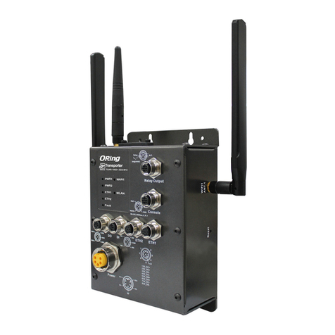
  9. ORiNG TGAP-W6610+-M12 User manual

ORiNG TGAP-W6610+-M12 User manual

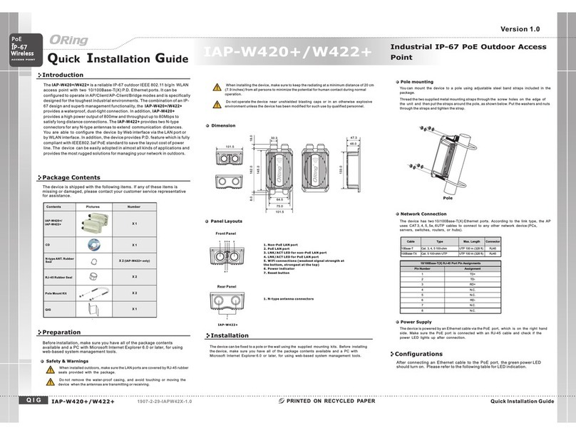
Quick Installation Guide
Version 1.0
Quick Installation Guide
Introduction
PRINTED ON RECYCLED PAPER
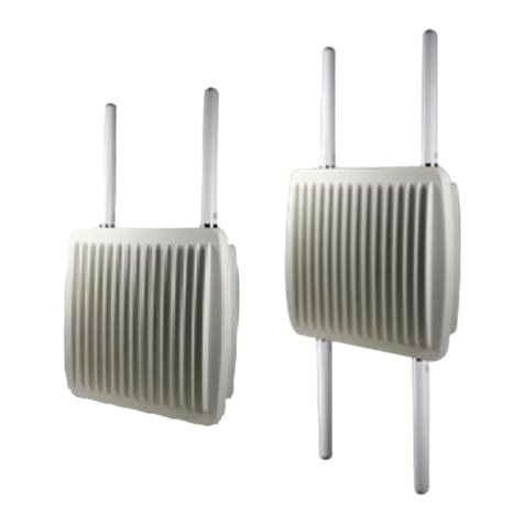
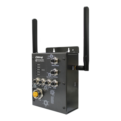
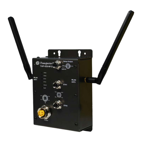
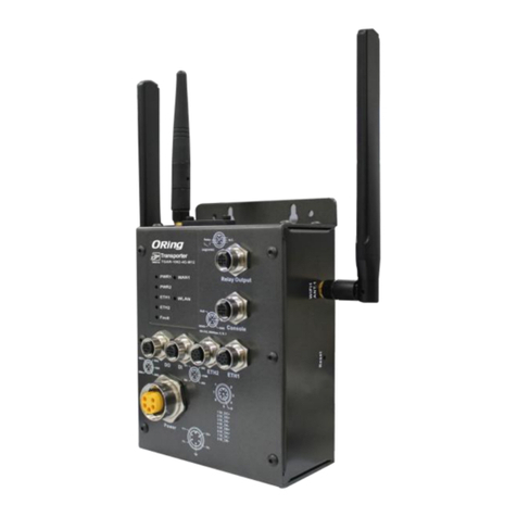
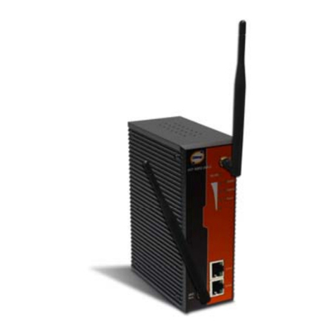
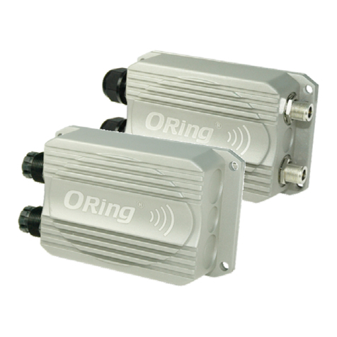
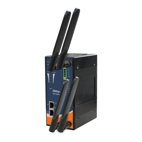
The are reliable outdoor WLAN access points
with one or dual 802.11 a/b/g/n wireless
modules alongside one Gigabit LAN port in M12 connector. With EN50155
compliance and M12 connectors to ensure tight and robust connections,
the devices guarantee reliable operation against vibration and shock, and
are ideal for rolling stock applications. The devices have an IP-67
waterproof housing to protect them from damage in harsh weather when
installed outdoors. Featuring two or four N-Type connectors that can house
any N-Type antennas for extended communications distances, the devices
are ideal for the toughest industrial environments. In addition, the LAN port of
the devices is PoE-enabled, allowing the device to be powered over the
existing network cable. The APs can be configured to operate in
AP/Client/Bridge/AP-Client modes and support MAC filters for security
control. Configurations and management can be done via a Window utility or
Web interface on LAN or WLAN networks.
TGAP-W610+-/W6610+-M12
(TGAP-W610+) (TGAP-W6610+)
Package Contents
Wall-mount
Follow the steps below to install the device to the wall.
Attach the mounting plate to the back of the device using four screws. The plate can
be attached vertically or horizontally to the device depending on the space available.
Step 1:
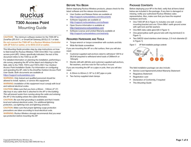
The are shipped with the following items. If any
of these items is missing or damaged, please contact your customer service
representative for assistance.
TGAP-W610+/6610+-M12
For pin assignments of power, console and relay output ports, please refer to the following tables.
Contents
CD
TGAP-W6610+-M12
TGAP-W610+-M12
Pictures Number
1
1
1
2.4GHz/5GHz
Antenna
2 (TGAP-W610+-M12) or
4 (TGAP-W6610+-M12)
Dimension
Wireless
EN50155
ACCESS POINT
EN50155 Industrial IP-67 PoE
Outdoor Access Point
Wiring
Grounding
Grounding and wire routing help limit the effects of noise due to electromagnetic interference
(EMI). Run the ground connection from the grounding pin on the power connector to the grounding
surface prior to connecting devices.
POWER PORT PINOUTS
The device supports two sets of power supplies and uses the M12 5-pin
female connector on the front panel for the dual power inputs.
Insert a power cable to the power connector on the device.
Rotate the outer ring of the cable connector until a snug fit is
achieved. Make sure the connection is tight.
Step 1:
Step 2:
QIG 1907-2-29-TGAPW-1.0
TGAP-W610+/6610+-M12 Series
1
Preparation
Before you begin installing the device, make sure you have all of the package
contents available and a PC with Microsoft Internet Explorer 6.0 or later, for
using web-based system management tools.
When installed outdoors, make sure the connectors on the panel are facing
down to prevent water intrusion.
Do not remove the water-proof casing, and do not touch or move the
device when the antennas are transmitting or receiving signals.
When installing the device, make sure to keep the radiating at a minimum
distance of 20 cm (7.9 inches) from all persons to minimize the potential for
human contact during normal operation.
Do not operate the device near unshielded blasting caps or in an otherwise
explosive environment unless the device has been modified for such use by
qualified personnel.
Safety & Warnings
IP-67
PoE
Panel Layouts
Bottom Panel
1
TGAP-W6610+-M12
1. Power connector
2. LED for PWR1 status
3. LED for PWR2 status
4. LED for PoE status
5. LED for WLAN2 connection
6. LED for WLAN1 connection
7. LED for LAN port connection
8. Reset button
9. LAN port
10. Connector for WiFi2 antenna
3
42
6
7
5
8 9 1010
1
TGAP-W610+-M12
3
42
6
7
5
8 9
Top Panel
1 1
1. Antenna connector
forWiFi(WiFi1)
Installation
The device can be fixed to a pole or the wall
using the supplied mounting plate. Make
sure the connectors on the bottom panel are
facing down when installing to prevent water
intrusion.
Wall mount x1
Stainless tie
back straps x2
Wood Screw x4
Wood/ Gyprock Plug x4
M6x12 Screw x4
Washer x4
Spring Washer x4
QIG
Mounting
Installation
Package 1
Wall-mount
screw holes
Strap slots for
pole mounting
Screw holes for
attaching the
plate to the
unit
Vertical Horizontal
Step 2:
Step 3:
Hold the device upright against the wall.
Insert four screws through the holes at the top and bottom of the plate and fasten the
screws to the wall.
Pole-mount
You can mount the device to a pole using the adjustable steel band straps included in the kit. Follow
the steps below:
Attach the mounting plate to the back of the device using four screws. The plate can be
attached vertically or horizontally to the device based on the space available.
Step 1:
Vertical Horizontal
Step 2: Thread the two supplied metal mounting straps through the large slots on the
mounting plate and then put the straps around the pole.
V1+
V1-
V2+
V2-
V1+
V1-
V2+
V2-
V1+
V1-
V2+
V2-
QIG Quick Installation Guide
Quick Installation Guide
ORing Industrial Networking Corp.
Copyright© 2014 ORing
All rights reserved.
TEL: +886-2-2218-1066
FAX: +886-2-2218-1014
Website: www.oring-networking.com
E-mail: [email protected]
Version 1.0
QIG
Configurations
After installing the router and connecting cables, start the evice by
turning on power. The green power LED should turn on. Please refer to
the following tablet for LED indication.
d
1. Launch the Internet Explorer and type in IP address of the device. The default static
IP address is 192.168.10.2
Specifications
Follow the steps below to log in and access the system:
2. Log in with default user name and password (both are ).admin
3. After logging in, you should see the following screen. For more information on configurations, please
refer to the user manual. For information on operating the device using ORing’s Open-Vision management
utility, please go to ORing website.
Resetting
To restore the device configurations back to the factory defaults, press the button for a few
seconds. Once the power indicator starts to flash, release the button. The device will then reboot
and return to factory defaults.
Reset
Regulatory Approvals
FCC Part 15, CISPR (EN55022) class A, EN50155 (EN50121-3-2, EN55011, EN50121-4)
EMI
EN61000-4-2 (ESD), EN61000-4-3 (RS), EN61000-4-4 (EFT), EN61000-4-5 (Surge),
EN61000-4-6 (CS), EN61000-4-8, EN61000-4-11
EMS
IEC60068-2-27, EN61373
Shock
IEC60068-2-32
IEC60068-2-6, En61373
Vibration
Free Fall
Warranty
5 years
Frequency Band
Transmission Rate
Encryption Security
WEP: (64-bit, 128-bit key supported)
WPA/WPA2: (WEP and AES encryption)
WPA-PSK (256-bit key pre-shared key supported)
802.1X Authentication supported
TKIP encryption
802.11i
Wireless Security SSID broadcast disable
Transmit Power
Receiver Senstivity
Protocol Support
Protocol ARP,BOOTP,DHCP,DNS,HTTPs,IP,ICMP,SNTP,TCP,UDP,RADIUS,SNMP,STP,RSTP
LED Indicators
Power Indicator
10/100/1000Base-T(X) port
Indicator
3 x LEDs, PW1/ PW2/ PoE Green On : Power is on and booting up PW1/ PW2/ PoE
1 x LED, Green for port Link/Act
WLAN LED
EN60950-1
Safety
ORing WLAN Access
Point Model
10/100/1000Base-T(X) Ports in
M12 Auto MDI/MDIX
(8-pin A-coding)
1
Physical Ports
Technology
Modulation
WLAN Interface
Operating Mode
Antenna and Connector 2 x External N type antenna connector
Radio Frequency Type DSSS, OFDM
TGAP-W6610+-M12
IEEE802.11b: CCK, DQPSK, DBPSK
IEEE802.11g: OFDM with BPSK, QPSK, 16QAM, 64QAM
IEEE802.11a: OFDM with BPSK, QPSK, 16QAM, 64QAM
IEEE802.11n: OFDM with BPSK, QPSK, 16QAM, 64QAM
America / FCC : 2.412~2.462 GHz (11 channels)
5.180~5.240 GHz & 5.745~5.825 GHz(9channels)
EuropeCE/ETSI:2.412~2.472Ghz(13channels)
5.180~5.240 Ghz (4 channels)
802.11a: -68dBm±2.0dB @ 54 Mbps
802.11b: -82dBm dB @ 11Mbps
802.11g: -68dBm dB @ 54Mbps
802.11gn HT20: -64dBm
±2.0
±2.0
±2.0dB @150Mbps
802.11gn HT40: -60dBm±2.0dB @300Mbps
802.11an HT20: -64dBm±2.0dB @150Mbps
802.11an HT40: -60dBm±2.0dB @300Mbps
2 x LEDs, Green for WLAN Link/Ack
IEEE801.11b: 1/ 2/ 5.5/ 11 Mbps
IEEE801.11a/g: 6/ 9/ 12/ 18/ 24/ 36/ 48/ 54 Mbps
IEEE802.11n: up to 300Mbps
802.11a: 12dBm dBm
802.11b: 18dBm dBm
802.11g: 15dBm dBm
802.11gn HT20: 13dBm m@150Mbps
802.11gn HT40: 12dBm m@300Mbps
802.11an HT20: 12dBm m@150Mbps
802.11an HT40: 12dBm dBm@300Mbps
±1.5
±1.5
±1.5
±1.5 dB
±1.5 dB
±1.5 dB
±1.5
TGAP-W610+-M12
PoEP.D.port
Present at ETH
Fully compliant with IEEE 802.3af Power Device specification
Over load & short circuit protection
IsolationVoltage:1000VDCmin.
Isolation Resistance : 10 ohms min
8
Dual AP/Dual Client /Bridge /AP-Client Mode
4 x External N type antenna connector
1 x LED, Green for WLAN Link/Ack
Network Connection
The AP has one 10/100/1000 Base-T(X) Ethernet ports. According to the link type, the AP uses
CAT 3, 4, 5, 5e, UTP cables to connect to any other network device (PCs, servers,
evicees, routers, or hubs). Please refer to the following table for cable specifications.d
Cable Type Max. Length Conn ecto r
10Base-T Cat. 3, 4, 5 100-ohm UTP 100 m ( 328 f t) M12
100Base-T Cat. 5 100-ohm UTP UTP 100 m ( 328 f t) M12
1000Base-T Cat. 5/Cat. 5e 100-ohm UTP UTP 100 m ( 328 f t) M12
M12/8P Pin Definition
4
5
6
7
8
21
3
PIN Definition
1BI_DC+
2BI_DD+
3BI_DD-
4BI_DA-
5BI_DB+
6BI_DA+
7BI_DC-
8BI_DB-
LED Color Status Description
PWR1 Green On DC power 1 activated
PWR2 Green On DC power 2 activated
PoE Green On Power is supplied over Ethernet cabl e
On Port is linked
ETH Green
Blinking Transmitting Data
On WLAN activatedWLAN
(1/2) Green
Blinking Transmitting WLAN data
Power
Power Consumption(Typ.) 11 Watts
Physical Characteristic
Enclosure IP-67
Dimension(WxDxH) 310(W) x 310(D) x 87(H) mm (12.2 x 12.2 x 3.4 inch.)
Weig ht ( g)
Environmental
-40to85 C(-40to185 F)
oo
Storage Temperature
5% to 95% Non-condensing
Operating Humidity
-25to70 C(-13to158 F)
oo
Operating Temperature
3980 g
9 Watts
3900 g
EN50155
Rail Traffic
EN60068-2-1
EN60068-2-2
Dry Heat
Cooling
Wireless
EN50155
ACCESS POINT
EN50155 Industrial IP-67 PoE
Outdoor Access Point
TGAP-W610+/6610+-M12 Series
IP-67
PoE
AP/Client /Bridge /AP-Client Mode
TGAP-W610+/6610+-M12 Series

This manual suits for next models

1

Other ORiNG Wireless Access Point manuals

ORiNG TGAR-1062-M12-3G User manual

ORiNG

ORiNG TGAR-1062-M12-3G User manual

ORiNG IGAP-W99110GP+ User manual

ORiNG

ORiNG IGAP-W99110GP+ User manual

ORiNG TAP-620-M12 User manual

ORiNG

ORiNG TAP-620-M12 User manual

ORiNG iar-120 series User manual

ORiNG

ORiNG iar-120 series User manual

ORiNG TGAP-620-M12 Series User manual

ORiNG

ORiNG TGAP-620-M12 Series User manual

ORiNG IAP-6002-WA User manual

ORiNG

ORiNG IAP-6002-WA User manual

ORiNG TGAP-820-M12 User manual

ORiNG

ORiNG TGAP-820-M12 User manual

ORiNG IAP-W420+ User manual

ORiNG

ORiNG IAP-W420+ User manual

ORiNG IAR-320 series User manual

ORiNG

ORiNG IAR-320 series User manual

ORiNG IAP-320+ User manual

ORiNG

ORiNG IAP-320+ User manual

ORiNG TGAP-W6610+ Series User manual

ORiNG

ORiNG TGAP-W6610+ Series User manual

ORiNG IGR-20 Series User manual

ORiNG

ORiNG IGR-20 Series User manual

ORiNG TAR-120/3120-M12 User manual

ORiNG

ORiNG TAR-120/3120-M12 User manual

ORiNG IAP-W510 Plus User manual

ORiNG

ORiNG IAP-W510 Plus User manual

ORiNG IAP-420 Series User manual

ORiNG

ORiNG IAP-420 Series User manual

ORiNG IAP-6701-WG+ User manual

ORiNG

ORiNG IAP-6701-WG+ User manual

ORiNG IAP-W510 User manual

ORiNG

ORiNG IAP-W510 User manual

ORiNG IAP-620 Series User manual

ORiNG

ORiNG IAP-620 Series User manual

ORiNG IGAR-1042 series User manual

ORiNG

ORiNG IGAR-1042 series User manual

ORiNG Transporter TAP-3120-M12 User manual

ORiNG

ORiNG Transporter TAP-3120-M12 User manual

ORiNG IAP-W510 User manual

ORiNG

ORiNG IAP-W510 User manual

ORiNG IGAP-610H+ User manual

ORiNG

ORiNG IGAP-610H+ User manual

ORiNG IGAP-420 series User manual

ORiNG

ORiNG IGAP-420 series User manual

ORiNG IAP-W510 User manual

ORiNG

ORiNG IAP-W510 User manual

Popular Wireless Access Point manuals by other brands

Devolo WiFi pro 1750e instruction manual

Devolo

Devolo WiFi pro 1750e instruction manual

Ubiquiti UniFi user manual

Ubiquiti

Ubiquiti UniFi user manual

Lantech IWP-2000-68 user manual

Lantech

Lantech IWP-2000-68 user manual

D-Link DWL-2200AP - AirPremier - Wireless Access... install guide

D-Link

D-Link DWL-2200AP - AirPremier - Wireless Access... install guide

Astronics Sierra E71-314 user manual

Astronics

Astronics Sierra E71-314 user manual

H3C WA6020 installation guide

H3C

H3C WA6020 installation guide

ANTAIRA ARS-7235-PSE-AC Series Hardware manual

ANTAIRA

ANTAIRA ARS-7235-PSE-AC Series Hardware manual

Nortel 7220 Installing guide

Nortel

Nortel 7220 Installing guide

D-Link DAP-1150 Quick installation guide

D-Link

D-Link DAP-1150 Quick installation guide

Cisco AIR-BR1310G-A-K9-R - Aironet 1310 Outdoor Access... datasheet

Cisco

Cisco AIR-BR1310G-A-K9-R - Aironet 1310 Outdoor Access... datasheet

Siemens SCALANCE X204RNA EEC operating instructions

Siemens

Siemens SCALANCE X204RNA EEC operating instructions

4IPNET EAP701 Quick installation guide

4IPNET

4IPNET EAP701 Quick installation guide

Ubiquiti UniFi Dream Machine Beacon quick start guide

Ubiquiti

Ubiquiti UniFi Dream Machine Beacon quick start guide

D-Link DAP-2230 Quick installation guide

D-Link

D-Link DAP-2230 Quick installation guide

GO Networks MBW 510 installation guide

GO Networks

GO Networks MBW 510 installation guide

Xirrus Wi-Fi Array XN16 user guide

Xirrus

Xirrus Wi-Fi Array XN16 user guide

Huawei eA660 Series user guide

Huawei

Huawei eA660 Series user guide

Arista C-250 quick start guide

Arista

Arista C-250 quick start guide

manuals.online logo
manuals.online logoBrands
  • About & Mission
  • Contact us
  • Privacy Policy
  • Terms and Conditions

Copyright 2025 Manuals.Online. All Rights Reserved.