manuals.online logo
Brands
  1. Home
  2. •
  3. Brands
  4. •
  5. ORiNG
  6. •
  7. Wireless Access Point
  8. •
  9. ORiNG IGAP-610H+ User manual

ORiNG IGAP-610H+ User manual

Quick Installation Guide
Version 2.0
Quick Installation Guide
PRINTED ON RECYCLED PAPER
Q I G 1907-200-G610H+XXX2-FX010
Installation
DIN-rail
Step 1 : Slant the device and screw the Din-rail kit onto the back of the device, right in the
middle of the back panel.
Step 2 :Slide the device onto a DIN-rail from the Din-rail kit and make sure the device clicks
into the rail firmly.
Dimension Unit =mm (Tolerance ±0.5mm)
Panel Layouts
Front Panel
IGAP-610H+
IGAP-610H+
Introduction
is a reliable WLAN Access Point with 1 Ethernet Gigabit portsIGAP-610H+
and IEEE 802.11 a/b/g/n wireless module. It can be configured to operate in
AP/Client/Repeater Mode. You are able to configure by WEBIGAP-610H+
interface via LAN port or WLAN interface. In addition, alsoIGAP-610H+
provides P.D. feature on Ethernet port which is fully compliant with
IEEE802.3af PoE P.D. specification. Therefore, is one of theIGAP-610H+
best communication solutions for wireless applications on the industrial
network.
Package Contents
The device is shipped with the following items. If any of these items is
missing or damaged, please contact your customer service representative
for assistance.
Contents
IGAP-610H+
Pictures Number
X 1
QIG X 1
Preparation
Before installation, make sure you have all of the package contents available and a PC
with Microsoft Internet Explorer 6.0 or later, for using web-based system management
tools.
Safety & Warnings
DIN-rail kit X 1
Wall-Mount Kit X 2
Wall-mount
1
4
3
5
Step 1: Screw the two pieces of wall-mount kits to the top and bottom panels of the
device. A total of screws are required, as shown below.eight
Step 2: Use the device, with wall mount plates attached, as a guide to mark the correct
locations of the four screws.
Step 3: Insert a screw head through middle of the keyhole-shaped aperture on the plate,
and then slide the device downwards. Tighten the screw head for added stability.
Elevated Operating Ambient: If installed in a closed environment, make sure the
operating ambient temperature is compatible with the maximum ambient temperature
(Tma) specified by the manufacturer.
Reduced Air Flow: Make sure the amount of air flow required for safe operation of the
equipment is not compromised during installation.
Mechanical Loading: Make sure the mounting of the equipment is not in a hazardous
condition due to uneven mechanical loading.
Circuit Overloading: Consideration should be given to the connection of the equipment to
the supply circuit and the effect that overloading of the circuits might have on overcurrent
protection and supply wiring. Appropriate consideration of equipment nameplate ratings
should be used when addressing this concern.
Features
High Speed Air Connectivity: Dual Band in IEEE 802.11 a/b/g/n and b/g/n WLAN
interface selectable and support up to 300Mbps link speed
12~48VDC power input on terminal block
1 Gigabit Ethernet ports with 2KV isolation for PoE P.D.
Highly Security Capability: WEP/WPA/WPA-PSK(TKIP,AES)/ WPA2/WPA2-PSK (TKIP,
AES)/802.1X Authentication supported
Support X-Roaming < 100 ms
Support Multiple-SSID to 4 SSID with VLAN
Support MAC Filter
High transmission power (27 dBm Max.)
High data throughput with HT40 2x2 MIMO
Support Long Distance Air Connectivity
Support AP/Client/Repeater
Wireless connecting status monitoring
Secured Management by HTTPS
Event Warning by Syslog, Email, SNMP Trap, and Relay output
Rigid IP-30 housing design
DIN-Rail and Wall-mount enabled
Wi r e l e ss
ACCES S POI NT
I N D U S T R I A L
Industrial Wireless LAN Access
Point
4-pin terminal block X 1
Power cable with
power jack X 1
25.0
46.0
5.0
24.0
40.0
45.0
25.5
50.0
33.6
115.0
45.0
46.7 22.5 25.8
95.0
173.0
145.0
18 0.13 5.
8 0.53.5
Ø5.0
Ø5.0
Ø10.0
LNK/AC T
Speed10/100 /1000M
WLAN
SYS
WLAN
ANT.1
WLAN
ANT.2
P1 P2
IGAP-610H+
PoE
ETH1
PoE
(P.D.)
LNK/ACT
Spee d10/1 00/1000 M
WLAN
SYS
WLA N
ANT.1
WLA N
ANT.2
P1 P2
IGAP-610H+
PoE
ETH 1
PoE
(P.D.)
2
1. Power LED
2. System LED
3. PoE power status
4. WLAN Antenna
5. LED for wireless signal strength
6. LNK/ACT LED for Giga PoE LAN
port
7. Giga PoE LAN port
8. Speed LED for Giga PoE LAN port
6
7
8
Rear Panel
1. Din-rail screw holes
2. Wall-mount screw holes
1
2
2
Top Panel
1
1. Terminal block
2. Reset button
3. Grounding screw
LNK/A CT
Speed10/10 0/1000M
WLAN
SYS
WLAN
ANT.1
WLAN
ANT.2
P1 P2
IGAP-610H+
PoE
ETH1
PoE
(P.D.)
Wiring
The device supports dual redundant power supplies, Power Supply1 (PWR1)
and Power Supply 2 (PWR2). The connections for PWR1, PWR2 are located
on the terminal block.
PWR-1PWR-2
V2- V2+ V1- V1+
Power inputs
STEP 1: Insert the negative/positive wires into the V-/V+ terminals,
respectively.
STEP 2: To keep the DC wires from pulling loose, use a small flat-blade
screwdriver to tighten the wire-clamp screws on the front of the terminal block
connector.
Network Connection
The device has three standard Ethernet ports. According to the link type, the device uses
CAT 3,4,5,5e UTP cables to connect to any other network devices (PCs, servers, switches,
routers, or hubs). Please refer to the following table for cable specifications.
2 3
CD X 1
Cable Types and Specifications:
Cable
Type
Max. Length
Connector
10BASE-T Cat. 3, 4, 5 100-ohm UTP 100 m (328 ft) RJ-45
100BASE-TX Cat. 5 100-ohm UTP UTP 100 m (328 ft) RJ-45
1000BASE-T Cat. 5/Cat. 5e 100-ohm UTP UTP 100 m (328ft) RJ-45
Q I G Quick Installation Guide
PRINTED ON RECYCLED PAPER
Quick Installation Guide
Q I G
Version 2.0
Specifications
Configurations
After installing the device and connecting cables, the green power LED
should turn on. Please refer to the following tablet for LED indication.
ORing Industrial Networking Corp.
Copyright© 2018 ORing
All rights reserved.
TEL: +886-2-2218-1066
FAX: +886-2-2218-1014
Website: www.oringnet.com
E-mail: support@oringnet.com
RJ-45 Pin Assignment
10/100 Base-T(X) RJ-45 port
Pin Number Assignment
1 TD+
2 TD-
3 RD+
4 Not used
5 Not used
6 RD-
7 Not used
8 Not used
1000Base-T RJ-45 port
Pin Number Assignment
1BI_DA+
2BI_DA-
3BI_DB+
4BI_DC+
5BI_DC-
6BI_DB-
7BI_DD+
8BI_DD-
Note: “+” and “-” signs represent the polarity of the wires that make up each wire pair.
IGAP-610H+
Wi r e l e ss
ACCES S POI NT
I N D U S T R I A L
Industrial Wireless LAN Access
Point
LED
Color
Status
Description
P.O.E Green On PoE power on
P1/ P2 Green On DC power 1/2 is activated.
SYS Green On System is ready
Blinking System is booting up
WLAN Green On WLAN activated
Blinking Transmitting wireless data
WLAN Strength Green On WLAN signal strength.
1<25%, 2<50%, 3<75%, 4<100%
10/100/1000Base-T(X) Fast Ethernet ports
LNK/ACT Green On Port is activated
Speed
Green On Port is linked and running at 1000Mbps.
Amber On Port is linked and running at 100Mbps.
Off Port is linked and running at 10Mbps.
1. Launch the Internet Explorer and type in IP address of the switch. The default static IP
address is 192.168.10.2
Follow the steps to set up the card:
2. Log in with default user name and password (both are admin).
Power
Redundant Input pow er Du al D C inputs. 12~48VD C on 4 p in termin al b lock
Physical Characteri stic
En cl os ure IP-30
Di me ns ion (W x D x H) 4 5 (W) x 95 (D) x 115( H)mm (1.77x 3. 74x4.53 inc h.)
Weight (g)
Environmental
-4 0 to 8 5 C ( -40 to 185 F)
o o
St orage Tem pe rature
5% t o 95 % Non-conde nsing
Op erating Humidity
-1 0 to 7 0 C ( 14 to 158 F)
o o
Op erating Tem pe rature
37 5g
Power Consumption (Typ.) 7 Watts
Ov er load current protec ti on Pr es ent
Reverse polarit y pr otection Pr es ent on termin al block
Protocol Support
Pr ot oc ol ARP,BOOT P, DH CP, DN S, HTTP, IP, ICMP, SNTP, TCP, UD P, RA DIUS, SNMP, STP, RSTP
Regulatory Approval s
EN 5 50 32, CISPR32 , EN 61000-3- 2, E N 61000-3-3 , FCC Part 15 B class A
EM I
EN 5 50 24 (IEC/EN 61 000-4-2 (ES D) , IEC/EN 6100 0- 4-3 (RS), IEC /EN 61000-4 -4 ( EF T), IEC/EN 61 00 0-4-5 (Su rg e),
IE C/ EN 61000-4- 6 (CS), IEC/E N6 1000-4-8( PF MF), IEC/EN 6 1000-4-11 (D IP))
EM S
IE C6 0068-2-27
Sh oc k
IE C6 0068-2-31
IE C6 0068-2-6
Vi bration
Fr ee Fall
MTBF
21 14 77 hrs
EN60950-1
Sa fe ty
An te nn a Connector Reverse SMA Female
Mo du la tion
Wi re le ss Security SS ID broadcast disable an d en ab le
IE EE 80 2.11a: OFDM
IE EE 80 2.11b: CCK/DQPSK/DB PS K
IE EE 80 2.11g: OFDM
IE EE 80 2.11n: BPSK, QPSK, 16 -Q AM , 64-QAM
Op erating Mode A P/ Client/Re pe at er
Fr eq ue ncy Band
Am er ic a / FCC : 2.412~2.462 GHz ( 11 c ha nnels)
5. 18 0~ 5.240 GHz & 5.745~5.8 25 G Hz ( 9 c hannels )
Eu ro pe C E / ETSI : 2.412~2.47 2 GH z (1 3 channels)
5. 18 0~ 5.240 GHz (4 channels )
Transmissi on Rate
80 2. 11 b: 11, 5.5, 2, 1 Mbps
80 2. 11 g: 54, 48, 36, 24, 18, 12 , 9, 6 Mb ps
80 2. 11 n: up to 300Mbps
Transmit Power
80 2. 11 a: 23dBm ± 1.5dBm@6Mb ps , 21 dBm ± 1.5dBm@54Mbps
80 2. 11 b: 23dBm ± 1.5dBm@1Mb ps , 23 dBm ± 1.5dBm@11Mbps
80 2. 11 g: 23dBm ± 1.5dBm@6Mb ps , 21 dBm ± 1.5dBm@54Mbps
80 2. 11 gn HT20: 20dBm ± 1.5dBm @M CS 7, 802.11gn HT40: 20d Bm ± 1 .5 dBm @MCS7
80 2. 11 an HT20: 20dBm ± 1.5dBm @M CS 7, 802.11an HT40: 20d Bm ± 1 .5 dBm @MCS7
Receiver Sensit iv ity
80 2. 11 a : -93dBm @6 Mb ps , -74dBm @5 4M bp s± 2d Bm ± 2d Bm
80 2. 11 b : -98dBm @1 Mb ps , -90dBm @1 1M bp s± 2d Bm ± 2d Bm
80 2. 11 g : -90dBm @6 Mb ps , -77dBm @5 4M bp s± 2d Bm ± 2d Bm
80 2. 11 gn HT20:-74dBm @MCS7, 802.11gn HT4 0: -7 1dBm @MCS 7± 2d Bm ± 2d Bm
80 2. 11 an HT20:-71dBm @MCS7, 802.11an HT4 0: -6 8dBm @MCS 7± 2dBm ± 2d Bm
En cr yp tion Security
WE P: ( 64 -bit ,128-bit key s up po rted)
WPA/WPA2 PS K: T KI P and AES encryption (8 02 .1 1i)
80 2. 1X Authentication s up po rt ed
WLAN Feature
10 /1 00 /1000Base-T(X) Ports in
Au to M DI/MDIX 1
Physical Ports
IG AP-610H+
ORing WLAN Access Point
Model
An te nn a Connector 2
PoE P. D Port
Pr es en t at ETH1
Fu ll y co mpliant with IEEE 802 .3 af Power Device s pe ci fication
Ov er l oad & short circuit pro te ct ion
Is ol at ion Vol ta ge: 2000VDC min.
Is ol at ion Resista nc e: 1 0 ohms mi n
8
CE E MC ( EN 55024, EN 55 032), FCC Part 15B
EM C
Warranty
5 ye ars
Resetting
To restore the device configurations back to the factory defaults, press the Reset button
for a few seconds. Once the power indicator starts to flash, release the button. The
device will then reboot and return to factory defaults.
3.After logging in, you should see the following screen. For more information on
configurations, please refer to the user manual.
IGAP-610H+
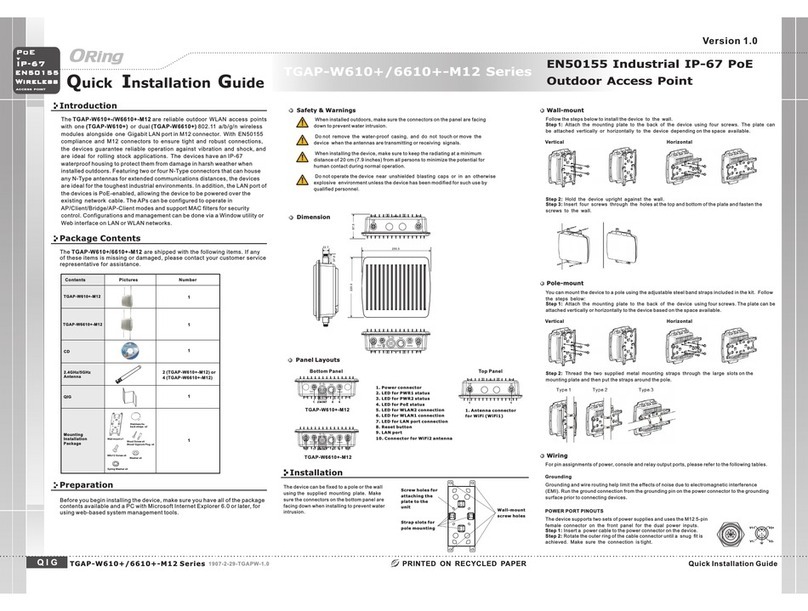
Other ORiNG Wireless Access Point manuals

ORiNG IAP-W510 User manual

ORiNG

ORiNG IAP-W510 User manual

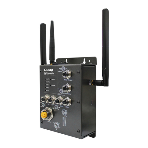
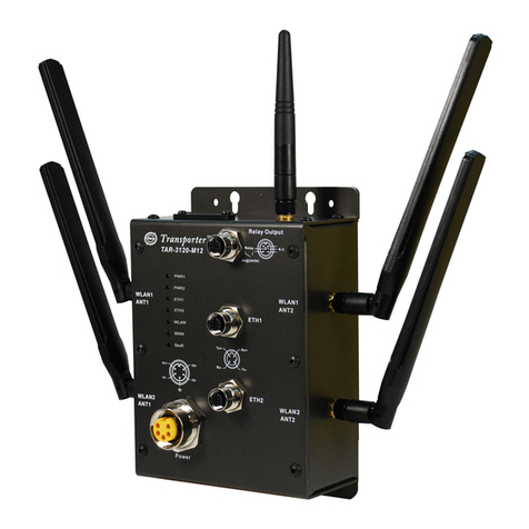
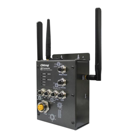
ORiNG Transporter TAP-3120-M12 User manual

ORiNG

ORiNG Transporter TAP-3120-M12 User manual

ORiNG IAP-420 Series User manual

ORiNG

ORiNG IAP-420 Series User manual

ORiNG IGAP-420 series User manual

ORiNG

ORiNG IGAP-420 series User manual

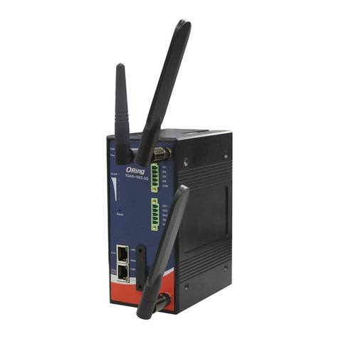
ORiNG IGAR-1042 series User manual

ORiNG

ORiNG IGAR-1042 series User manual

ORiNG IAP-620 Series User manual

ORiNG

ORiNG IAP-620 Series User manual

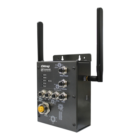
ORiNG TGAP-620-M12 Series User manual

ORiNG

ORiNG TGAP-620-M12 Series User manual

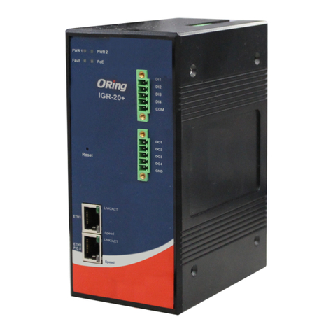
ORiNG IGR-20 Series User manual

ORiNG

ORiNG IGR-20 Series User manual

ORiNG TGAP-W6610+-M12 User manual

ORiNG

ORiNG TGAP-W6610+-M12 User manual

ORiNG IAP-320+ User manual
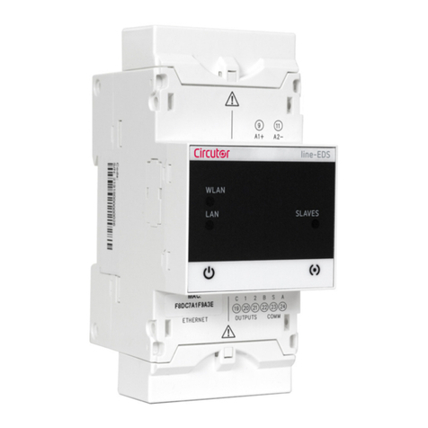
ORiNG

ORiNG IAP-320+ User manual

ORiNG iar-120 series User manual

ORiNG

ORiNG iar-120 series User manual

ORiNG TGAP-W6610+ Series User manual

ORiNG

ORiNG TGAP-W6610+ Series User manual

ORiNG TAP-620-M12 User manual

ORiNG

ORiNG TAP-620-M12 User manual

ORiNG IAP-W510 Plus User manual

ORiNG

ORiNG IAP-W510 Plus User manual

ORiNG IAP-W510 User manual

ORiNG

ORiNG IAP-W510 User manual

ORiNG IAP-620 Series User manual

ORiNG

ORiNG IAP-620 Series User manual

ORiNG IAP-W510 User manual

ORiNG

ORiNG IAP-W510 User manual

ORiNG IAP-6002-WA User manual

ORiNG

ORiNG IAP-6002-WA User manual

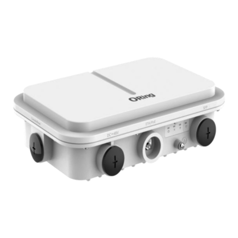
ORiNG IGAP-W99110GP+ User manual

ORiNG

ORiNG IGAP-W99110GP+ User manual

ORiNG IAR-320 series User manual

ORiNG

ORiNG IAR-320 series User manual

ORiNG TGAR-1062-M12-3G User manual

ORiNG

ORiNG TGAR-1062-M12-3G User manual

ORiNG TGAP-820-M12 User manual

ORiNG

ORiNG TGAP-820-M12 User manual

ORiNG IAP-6701-WG+ User manual

ORiNG

ORiNG IAP-6701-WG+ User manual

ORiNG IAP-W420+ User manual

ORiNG

ORiNG IAP-W420+ User manual

Popular Wireless Access Point manuals by other brands

Allied Telesis TQ6702e GEN2 installation guide

Allied Telesis

Allied Telesis TQ6702e GEN2 installation guide

Planex GW-AP11S user manual

Planex

Planex GW-AP11S user manual

Huawei AP3010DN-AGN quick start guide

Huawei

Huawei AP3010DN-AGN quick start guide

SmartBridges airPoint Pro Series Quick install guide

SmartBridges

SmartBridges airPoint Pro Series Quick install guide

Alcatel-Lucent Stellar AP Series Deployment & Configuration & Troubleshooting Guide

Alcatel-Lucent

Alcatel-Lucent Stellar AP Series Deployment & Configuration & Troubleshooting Guide

Airspan ProST 4.9 Hardware installation guide

Airspan

Airspan ProST 4.9 Hardware installation guide

Motion CMD-01 quick start guide

Motion

Motion CMD-01 quick start guide

CREWAVE CW-1100AP user guide

CREWAVE

CREWAVE CW-1100AP user guide

Cisco aironet 2800 series Deployment guide

Cisco

Cisco aironet 2800 series Deployment guide

EnGenius EOC2611P quick start guide

EnGenius

EnGenius EOC2611P quick start guide

MikroTik RBcAPL-2nD quick guide

MikroTik

MikroTik RBcAPL-2nD quick guide

Aironet Arlan 630 user guide

Aironet

Aironet Arlan 630 user guide

Juniper AP63 Deployment guide

Juniper

Juniper AP63 Deployment guide

D-Link DAP-1360U user manual

D-Link

D-Link DAP-1360U user manual

Samon SPU quick start guide

Samon

Samon SPU quick start guide

Cisco Aironet 1300 Series Hardware installation guide

Cisco

Cisco Aironet 1300 Series Hardware installation guide

Cerio 100GX-N user manual

Cerio

Cerio 100GX-N user manual

Asus WL 320gE - Wireless Access Point quick start guide

Asus

Asus WL 320gE - Wireless Access Point quick start guide

manuals.online logo
manuals.online logoBrands
  • About & Mission
  • Contact us
  • Privacy Policy
  • Terms and Conditions

Copyright 2025 Manuals.Online. All Rights Reserved.