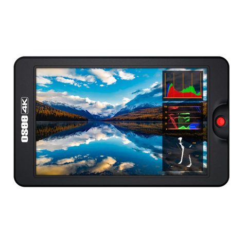
OSEE T5+ User manual

ON CAMERA Monitor
User Manual


Product Information
Model:
T5+ ON CAMERA Monitor
Version:
V010000
Release Date:
October 24th, 2022
Company
OSEE TECHNOLOGY LTD.
Contact Information
OSEE TECHNOLOGY LTD.
Address:
No.22 Building, No.68 zone, Beiqing Road, Haidian
District, Beijing, China
Post Code:
100094
Tel:
(+86) 010-62434168
Fax:
(+86) 010-62434169
Web:
http://www.osee-dig.com/
E-mail:

About this manual
Important
The following symbols are used in this manual:
The further information or know-how for described subjects above
which helps user to understand them better.
The safety matters or operations that user must pay attention to when
using this product.
Contents
The user manual applies to the following device types:
T5 PLUS
The images and descriptions of T5+ are adopted as examples in the
following document.
Before reading the manual, please confirm the device type.

I
Contents
Contents.....................................................................................................I
Chapter 1 Overview..................................................................................1
Chapter 2 Safety.......................................................................................3
Chapter 3 Unpack and Installation.........................................................7
Chapter 4 Features.................................................................................13
4.1 Parts and Functions....................................................................13
4.2 Buttons and Functions...............................................................14
4.3 Operations ...................................................................................15
4.4 Power On .....................................................................................18
4.5 ZOOM&PAN..................................................................................19
4.6 Supported Signal Format...........................................................22
Chapter 5 Monitor Settings...................................................................25
5.1 Menu Operations.........................................................................26
5.2 Monitor Menu...............................................................................27
5.2.1 INPUT.......................................................................................27
5.2.2 Controls....................................................................................28
5.2.3 Camera Profile .........................................................................32
5.2.4 System .....................................................................................39
Chapter 6 Scenes and Tools.................................................................43
6.1 Scenes Tools Settings................................................................43

II
6.1.1 Frame Tools.............................................................................45
6.1.2 Expose Tools............................................................................49
6.1.3 Focus Tools..............................................................................58
6.1.4 Look Tools................................................................................60
6.1.5 Analysis Tools..........................................................................65
6.1.6 Meter Tools ..............................................................................68
6.2 Tools Operations.........................................................................69
6.2.1 Add a Scene.............................................................................69
6.2.2 Delete a Scene.........................................................................70
6.2.3 Add a Tool................................................................................71
6.2.4 Load/Close Tool Bar ................................................................74
6.2.5 Turn ON/OFF a Tool................................................................75
6.2.6 Tool Settings ............................................................................76
6.2.7 Delete a Tool............................................................................78
Chapter 7 Specifications.......................................................................81
7.1 Product detailed information.....................................................81
7.2 Dimensions..................................................................................83

Overview
1
Chapter 1 Overview
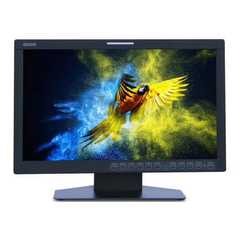
T5+ is a high-performance UHD HDMI On Camera Monitor to monitor
professional 4K HDMI for outdoor photography.
The unit is designed in a high impact plastic frame, and the professional
screen glass at full resolution of 1920x1080 with 450nit brightness makes
T5+ capable of reproducing a natural color. In addition, the monitor has
excellent assistant functionalities, versatile build-in color profiles and easy
to use.
Figure 1-1 A Diagram of T5+
Features
Support 4K HDMI input
Support output to external cameras, such as SONY, Panasonic,
Canon etc.
Support high qualified waveform, vector scope, histogram and
audio meter
Support multiple assistants: zebra, focus assist, exposure assist,
peaking adjust

Overview
2
Provide a five directions joystick as a navigation tool to scroll
between scenes pages and set features
Support SONY NP-F and Canon LP-E6 series batteries
Provide optional dummy battery adaptors to output battery DC
power to cameras
Functionality
Provide versatile build-in color profiles, supporting the general
profiles for ARRI, BMD, Canon, DCI, EBU, FUJI, NIKON,
Panasonic, RED and SONY, etc. And you can upload custom 3D
LUTs through SD card and apply to on Camera monitor
Support Anamorphic Desqueeze functionality in multiple modes:
1.33X, 1.4X, 1.5X, 1.6X, 1.8X, 1.9X, 2X
Support Image ZOOM functionality to double(2X) or
quadruple(4X) the image, and to pan the image in every
direction

Safety
3
Chapter 2 Safety
FCC Caution:
Any Changes or modifications not expressly approved by the party
responsible for compliance could void the user's authority to operate the
equipment.
This device complies with part 15 of the FCC Rules.
Operation is subject to the following two conditions: (1) This device may
not cause harmful interference, and (2) this device must accept any
interference received, including interference that may cause undesired
operation.
Note: This equipment has been tested and found to comply with the limits
for a Class B digital device, pursuant to part 15 of the FCC Rules. These
limits are designed to provide reasonable protection against harmful
interference in a residential installation. This equipment generates uses
and can radiate radio frequency energy and, if not installed and used in
accordance with the instructions, may cause harmful interference to radio
communications. However, there is no guarantee that interference will not
occur in a particular installation. If this equipment does cause harmful
interference to radio or television reception, which can be determined by
turning the equipment off and on, the user is encouraged to try to correct
the interference by one or more of the following measures:
Reorient or relocate the receiving antenna.
Increase the separation between the equipment and receiver.
Connect the equipment into an outlet on a circuit different from that to
which the receiver is connected.
Consult the dealer or an experienced radio/TV technician for help.
Warnings:
Read, keep and follow all of these instructions for your safety. Heed all
Safety
4
warnings.
Device
Install in accordance with the manufacturer's instructions.
Do not touch the screen with sharp, metallic or abrasive objects.
Do not make the freeze picture displaying on the screen time too
long, otherwise, it will leave the afterimage on the screen.
If the brightness is adjusted to the minimum, then it might be
hard to see the display screen.
Clean only with dry cloth.
Do not block any ventilation openings. Leave enough space
around the unit for ventilation.
Do not expose to strong electrical or magnetic fields.
To reduce the risk of fire or electric shock, do not expose the unit
to rain or moisture.
If the product needs replacement parts, make sure that the
service person use replacement parts specified by the
manufacture, or those with the same characteristics and
performance as the original parts. Use of unauthorized parts can
result in fire, electric shock and/or other damage.
The panel used in this produce is made of glass. Therefore, it
can break when it is dropped or applied with impact. Be careful
not to be injured by broken glass pieces.
Refer all servicing to qualified service personnel.
Specifications are subject to change without notice.
Do not use attachments or accessories not recommended by the
manufacture. Use of inadequate attachments may result in

Safety
5
serious accidents.
Do not damage the power cord, place the heavy objects on the
power cord, stretch the power cord, or bend the power cord.
Protect the power cord from being walked on or pinched,
particularly at plugs, convenience receptacles, and the point
where they exit from the unit.
Please remember that almost all HDMI cables do not use
locking connectors and will simply pull out if they are jerked or
tripped over. Please ensure your cables make a secure
connection and avoid flexing them excessively to maintain
reliability.


Unpack and Installation
7
Chapter 3 Unpack and
Installation
Unpack:
When unpacking the T5+ monitor, please verify that none of the
components listed in Table 3.1 are damaged or missing. If there are any
components missing, please contact your distributors or OSEE for it.
Table 3-1 Packing List
No.
Item
Quantity
1
T5+
1
2
Sunhood
1
3
Tilt Arm
1
4
HDMI TypeA to HDMI Micro 30cm Cable
1
5
HDMI TypeA to HDMI Mini 30cm Cable
1
6
Warranty Card
1
7
Certificate card
1
Optional Accessories: (sold separately)
When powered by battery, the BATT OUT interface can output battery DC
power to external cameras by using the dummy battery adaptors. We
provide the following four optional dummy battery adaptors:
Type
Description
T5+-Kit1
Optional, including SONY NP-FW50 dummy
battery and HDMI Micro cable

Unpack and Installation
8
Type
Description
T5+-Kit2
Optional, including SONY NP-FZ100 dummy
battery and HDMI Micro cable
T5+-Kit3
Optional, including Panasonic DMW-BLF19
dummy battery and HDMI Micro cable
T5+-Kit4
Optional, including CANON LP-E6 dummy
battery and HDMI Mini cable
Figure 3-1 Connect BATT OUT to Dummy Battery
Installation:
1. Prepare for installation
Please follow the procedures below before installing T5+:
Check the package and equipment for any visible damage that
may have occurred during transit.
Confirm all the items listed on the packing list have been
received.
Remove all the packing material including electrostatic-resistant
packing.

Unpack and Installation
9
Retain these packing materials for future use.
2. Connect required cables for signal input and output.
3. Connect the 5~17VDC power source through DC IN Type-C
interface or powered by battery.
4. As a final step, turn on the device by toggling the power
switch located on the rear of the unit.
Install Battery:
Only support SONY NP-F series and Canon LP-E6 battery currently. The
battery slot is bidirectional, and please take note of the battery installation
direction according to the “NP-F” or “LP-E” icon near the slot when
mounting the battery. The icons are as shown in the following illustration,
slide the battery down into the slot until heard a click.
Figure 3-2 Battery Installation
Install Sunhood:
In case of diffusion light and direct illumination, we can use sunhood for
the monitor when supervising images.
First, spread the sunhood along the fold lines, then pull the rubber belts
into the depressed slots at both sides of the rear panel of the monitor,
adapting to the monitor tightly as below:


Features
13
Chapter 4 Features
4.1 Parts and Functions
The parts of T5+ is shown as below, there are various input and output
interfaces for T5+ monitor, as shown in Figure 4.1-1.
Figure 4.1-1 Parts in Rear Panel
No.
Connector
Description
1
Power
Switch
Switch to
“|”
position to power on; and switch to
“”position to power off

Features
14
No.
Connector
Description
2
SD card slot, the SD card is used to load the
customized LUT tables, and update firmware.
3
HDMI IN
HDMI input interface, supports HDCP,
compatible DVI1.0, HDMI 1.4
4
Battery
Input
External battery NP-F, 5~17V
5
BATT OUT
Battery output, 5~8.4V
6
DC IN
DC power input, 5~17V, Type-C
7
Remote
Remote control, 2.5mm Jack
8
Headphone output jack, 3.5mm stereo Jack
* Support SONY NP-F and Canon LP-E6 battery currently.
4.2 Buttons and Functions
The monitor provides a Joystick at the front panel, as shown in Figure
4.2-1. It is used for monitor settings, adding tools for scenes, tools settings,
zoom image and so on.
Table of contents
Other OSEE Monitor manuals

OSEE
OSEE LMW-200 SERIES User manual

OSEE
OSEE FRM-173 Series User manual

OSEE
OSEE BCM-215 Series User manual

OSEE
OSEE XCM-240 User manual

OSEE
OSEE LCM215-E Series User manual

OSEE
OSEE LMW156 SERIES User manual

OSEE
OSEE RMM1024 User manual

OSEE
OSEE LMW-230 Series User manual

OSEE
OSEE MVM230 User manual

OSEE
OSEE G7 4K ULTRAHD User manual