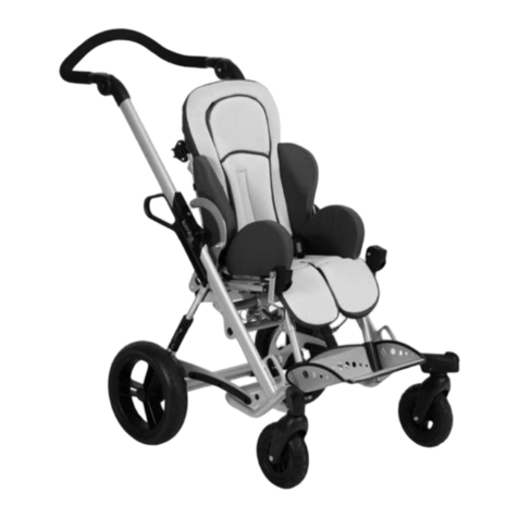
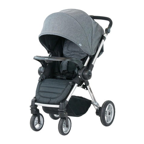
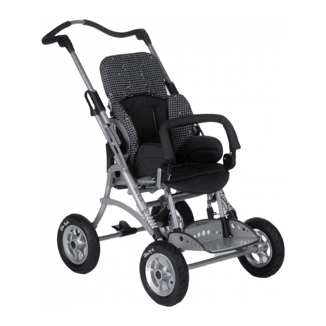
Otto Bock Kimba Cross User manual

Kimba Cross
Bedienungsanleitung .................................................. 7
Instruction for use ..................................................... 19
Gebruiksaanwijzing ................................................... 30
© Otto Bock HealthCare GmbH · 647G117 – 05.03/2 · Printed in Germany

4
3
5 6
1 2
10
7 8
13
9
11 12
14 15
B
➞
➞
➞
➞
➞
➞
➞
A
➞
➞
➞
➞

19
18
20 21
16 17
25
22 23
28
24
26 27
29 30
A
➞
➞
➞
➞
A
➞
➞
B
➞
➞
➞
➞

AB
BC
B
A
B
C
A
A
B
36
32
3534
3331
40
37 38
43
39
41 42
44 45
B
A
E
B
C
AD
A
B
A
D
C
B
A
E
A
B
A

49
48
50 51
46 47
55
52 53
58
54
56 57
59 60
B
A
C
A
B
A
B
B
A
A
B
A
B
A
C
B

64
63
65 66
61 62
70
67 68 69
71
C
A
A
A
73 74 75
72
B
A
A
B

19
Contents Pa e
Preface ................................................................................................................................................................. 20
Application – Indications ...................................................................................................................................... 20
Declaration of Conformity ....................................................................................................................................20
Service ................................................................................................................................................................. 20
Safety Instructions ............................................................................................................................................... 20
Unpacking and Setting up ...................................................................................................................................22
Outdoor Mobility Base .........................................................................................................................................22
Accessories for Outdoor Mobility Base ............................................................................................................... 23
Swivellin front wheel ............................................................................................................................................23
Splash uard for rear wheels/Clothin protectors ..................................................................................................23
Anti-tipper .............................................................................................................................................................23
Stora e ba ..........................................................................................................................................................23
Spoke protectors...................................................................................................................................................23
Use as a Bicycle Trailer ........................................................................................................................................ 23
Kimba Multifunctional Seating Unit .....................................................................................................................24
Seating Shell Interfaces.......................................................................................................................................25
Accessories for Kimba Multifunctional Seating Unit: .......................................................................................... 25
Abductor ...............................................................................................................................................................25
Armrest .................................................................................................................................................................25
Pelvic band ...........................................................................................................................................................25
Chest and shoulder pad ........................................................................................................................................25
Canopy .................................................................................................................................................................26
Fixation vest .......................................................................................................................................................... 26
Belts: Lap belt, four-point belt, foot straps .............................................................................................................. 26
Grab rail and rab rail paddin ..............................................................................................................................26
Headrests .............................................................................................................................................................27
Rain cape ..............................................................................................................................................................27
Slipsacks ..............................................................................................................................................................27
Groin strap ............................................................................................................................................................ 27
Tray .......................................................................................................................................................................27
Thoracic supports .................................................................................................................................................27
Using your Kimba Cross as a Seat in Motor Vehicles ......................................................................................... 28
Instructions for Maintenance and Cle*aning ........................................................................................................ 28
Warranty ...............................................................................................................................................................28
Technical Data .....................................................................................................................................................29
Instructions for Use for Kimba Cross –
Pediatric Postural Positioning System/Mobility Base for Seating Shells

20
Preface
The Kimba Cross mobility base / pediatric postural positionin system is a quality product offerin versatile use in
everyday life.
Before usin your Kimba Cross please read sections: "Unpackin and Settin up” and "Safety Instructions”. Please
keep these instructions in a safe place.
The section "Accessories” presents additional parts for the Kimba Cross, which may extend the ran e of application
and increase the comfort.
If you have any further questions, or if you have any problems, please contact your healthcare provider.
The desi n, as described in these Instructions for Use, is subject to technical alterations without notice.
Application – Indications
(Source: Catalo of aids and list of aids of the health insurance funds, FRG)
The prescription of a pediatric postural positionin system is enerally indicated for the severely disabled, especially for
children and youn people who are unable to walk, need to be transported and are unable to operate a wheelchair
themselves.
Inability to walk or very serious walkin impediment due to:
• Palsies
• Paralysis
• Loss of limbs
• Defective and/or deformed limbs
• Joint contractures
• Joint defects
• Other diseases
The Kimba Cross was specially desi ned for use with the Kimba seatin unit.
Declaration of Conformity
Otto Bock HealthCare GmbH as manufacturer with sole responsibility declares that the Kimba Cross mobility base/
pediatric postural positionin system conforms to the requirements of the 93/42/EEC Guidelines.
Service
Service and repairs on the Kimba Cross may only be carried out by Otto Bock healthcare providers. Should any
problems arise, please contact the supplier of your Kimba Cross. Any necessary repairs will be made exclusively with
authentic Otto Bock spare parts there.
Your authorized Otto Bock healthcare provider:
Safety Instructions
Before usin the Kimba Cross, you should become familiar with the handlin , function and use of the product.
a) When using the Kimba Cross with rigidly mounted or with swivelling front wheel:
• Get to know in particular how the Kimba Cross with your seatin system reacts when the center of ravity is shifted;
for example on slopes or inclines or when clearin obstacles, like steps and curbs.
• Use your Kimba Cross properly. For instance, do not drive into obstacles (includin steps, curbs) without brakin .
• Stairs should be ascended/descended only with assistance from an attendant. If devices such as ramps or elevators
are available, they should be used. If such devices are missin , two attendants must carry the Kimba Cross over the
obstacle.
• When usin liftin platforms, be sure the anti-tipper is outside the dan er-area.
• Only lift the Kimba Cross with parts that are solidly attached.
• Park the Kimba Cross only on level surfaces and always apply the drum brakes. Avoid parkin the Kimba Cross on
an incline.
Make sure that you brin the seat to an upri ht position.

21
• You must use the anti-tipper accessory whenever the center of ravity is shifted rearwards in the Kimba Cross
(such as when usin the swivellin front wheel, or when the backrest is in the sleepin position). With the center of
ravity shifted rearwards, and without the anti-tipper accesory, the Kimba Cross can tip over, even on a flat surface.
• Do not attach any objects to the pushbar which can affect the center of ravity.
• When your child reaches for objects in front, to the side or behind the Kimba Cross, make sure that he or she does
not lean out of it too far, since the shift in the center of ravity mi ht cause the Kimba Cross to tilt or tip over.
• Before leavin the Kimba Cross and before ettin into and out of it, always lock the brakes.
• Never leave your child unattended in the Kimba Cross, even if the belts are in use and the brakes are en a ed.
• Check the pneumatic tires for proper inflation levels (printed on the outer wall of the tire) and make sure the tires have
sufficient tread depth.
• Please keep packa in material away from children. Plastic packa in presents the dan er of suffocation.
• Trays must not be loaded with heavy objects.
• The Kimba Cross has been approved for the transport of only one child.
• All accessories and add-on components will reduce the remainin maximal load capacity.
• The maximal load for the Kimba seatin unit is 35 k . The Kimba Cross mobility base has a load capacity of 50 k .
b) Also, when using the Kimba Cross as a bicycle trailer:
• Never use a tray when usin the Kimba Cross as a bicycle trailer.
• The maximal sittin hei ht of the body (measurement from buttocks to head) must not exceed 70 cm.
• Be careful ridin the bicycle because the trailer will chan e how the bicycle handles and increase the stoppin
distance.
• Please note that when usin your Kimba Cross in the public traffic, you must observe the traffic re ulations accord-
in to the vehicle re ulations for your area. For this reason, all components of the trailer accessories packa e must
be mounted on the trailer.
• The child sittin in the trailer must wear seat belts and a safety helmet. A four-point belt and a roin strap must be
applied to prevent the child from slippin out of the Kimba Cross.
• This accessories packa e, not includin an additional brake (for use on the trailer) can be used with bicycle trailers
with a maximal total wei ht of 40 k .
• Modifications on the couplin and other additional assemblies are not allowed. Please observe these instructions,
otherwise you can expose your child and yourself to dan er.
• Only use the supplied "Weber” coupling.
• Read the Instructions for Use of the "Weber coupling" included with this unit as well as the instructions
attached to the draw-bar.
c) General safety instructions
•You must check the proper fit and clamping pressure of the axle!
• Be careful not to injure your fin ers durin adjustment and assembly.
• Use your Kimba Cross with Otto Bock seatin system only in accordance with the instructions for use.
•When usin a seatin unit from another manufacturer, this manufacturer must confirm compatibility.
• Every time you mount the wheels, make sure that the rear quick-release axles have engaged correctly and
that the front quick-release axle has been locked with sufficient clamping pressure.
• After each readjustment of the seat tilt, make sure that you firmly tighten the turning handle. Also check the
handle often during use.
• Make sure to snugly re-tighten the screws (two on the left and two on the right) after adjusting the telescoping
front frame.
• We would like to point out that children seated in the seating systems must at all time be secured with suitable
safety systems (straps/belts).
•Using your Kimba Cross as a seat in motor vehicles.
We recommend that, whereever and whenever possible, Kimba Cross users transfer to the seats installed in the
motor vehicle and use the correspondin vehicle restraint systems, because this is the only way to ensure optimal
protection of the passen ers in case of an accident. For the time bein , Otto Bock has not yet released the Kimba
Cross for use as a motor vehicle transportation seat. If you’d like to use it in this way, you must have your vehicle
specially outfitted with a restraint system that conforms to any applicable standards. Otto Bock will provide a
release upon request.
22
d) When using the Otto Bock Kimba seating unit:
• The footplate must not be used as a stepstool when ettin into or out of the Kimba seatin unit.
• Use caution near fire or flammable objects, especially when holdin lit ci arettes. The seat and back paddin could catch
fire.
Unpacking and Setting up
In the ori inal packa e you will find the followin components:
• Frame, folded
• Two rear wheels with quick-release axle
• One front wheel with quick-release lock and mounted splash uard
• Kimba seatin unit (if included in the order)
• Instructions for Use and Allen wrench, size 4
• Accessories as ordered
To unfold the frame please proceed as follows:
• Carefully remove the transport safety snaps and packa in material.
Next, remove the lockin pin from the frame lu s (Fi . 1).
• Fold up the pushbar (Fi . 2) and position the back brace between the two lu s. The back brace has three bore holes
which let you set the pushbar at different an les. Select the appropriate back brace hole for your desired pushbar
an le (Fi . 3). Put the lockin pin throu h the selected hole in the back brace and throu h the lu s and then secure
with the clip (Fi . 4). For mountin the rear wheels to the frame, insert the quick-release axles into the rear wheels
and press the quick-release axle with the wheel into the axle housin (Fi . 5). Make sure that the axles have
correctly locked in place! Mountin the front wheel: For mountin the standard, ri id-mount front wheel with pre-
assembled splash uard, please proceed as follows: Insert the front wheel with splash uard into the fork and push
it to the rear and up (Fi . 6). Close the eccentric lever of the quick-release axle. Make sure the recess in the back of
the splash uard en a es the crossbrace of the front frame (Fi . 7).
Important: Make sure the axle is properly engaged and has enough clamping pressure!
The clampin pressure can be adjusted by turnin the quick-release lever or the counternut.
• To fold the Kimba Cross to ether, please reverse the directions mentioned above.
Outdoor Mobility Base
Functions:
Pushbar
The pushbar can be adjusted in hei ht and an le to better fit the attendant.
Adjusting the Height of the Pushbar
Loosen the clampin lever on both sides, move the pushbar to the desired hei ht and re-ti hten the clampin levers
until they are snu (Fi . 13).
Adjusting the Angle of the Pushbar
Flip up the clip of the lockin pin and pull out the lockin pin to release the back brace. Choose another hole in the
back brace to chan e the pushbar an le. There are three possible positions. Reinsert the lockin pin and secure with
the clip (Fi . 14).
Brakes: Operation and Adjustment
Pull the lar e brake levers to apply the drum brakes (Fi . 72, item A). Simultaneously move the small levers downwards
(Fi . 72, item B) to lock the brakes. Pull the lar e brake levers (Fi . 72, item A) a ain to release the brakes.
You can adjust the drum brakes (independently on the left and ri ht side) to always achieve optimal brakin . To do this,
loosen the counter nut (Fi . 73, item A) and turn the adjustment nut (Fi . 73, item B) until you reach the brakin effect
you desire. Snu ly re-ti hten the counter nut.
Adjusting the Seat Tilt
To chan e the an le of the seatin unit, loosen the turnin handle on the left frame side (in drivin direction) up to the
stop. Next, push in the sprin -mounted turnin handle to release the adjustment bar. The seat can now be moved freely
around the axle of the seat adapter. Brin the seat into the desired position, release the turnin handle and wi le the
seat back and forth to re-en a e it with the adjustment bar.
Firmly re-tighten the turning handle! (Fi . 15).
Frame Length/Adjusting the Wheelbase
The telescopin front frame lets you use mounted seatin units of various sizes, and offers a wheelbase adjustment
ran e between 800 mm to 920 mm. To chan e the wheelbase, loosen and remove the two screws on either side of the
oval tube front frame. Push in or pull out the front section until the desired position has been reached (Fi . 16, 17).
Reposition the screws and snugly re-tighten. Each position must be secured with two screws on each side !

23
Outdoor Mobility Base – Accessories (optional)
The Kimba Cross mobility base is desi ned as a modular assembly system, which means that certain accessories may
be adapted to it. The followin options and accessories may make it easier to use your Kimba Cross mobility base (Fi .
18).
Swivelling Front Wheel
The optional swivellin front wheel reduces the turnin radius of your Kimba Cross, makin it easier to use in ti ht
spaces (Fi . 22). First, remove the ri id-mount front wheel and the mounted splash uard in the reverse order as
described under "Unpackin and Settin Up”.
Next, insert the swivellin front wheel into the fork as shown in Fi . 20 and push it to the rear and up. Make sure that the
attachment plate en a es with the slot of the crossbrace. Close the eccentric lever of the clamp axle (Fi . 21).
It is very important that you check for the proper fit and clamping pressure of the axle!
Splash Guard for Rear Wheels / Clothing Protectors
To mount these snap-on wheel covers, take off the rear wheels by first removin the quick-release axles (press the
central bolts to release the locks and pull the axles out). Pull the rear wheels off the axle housin s. Screw the attachment
elements for the splash uards to the holes provided for this purpose (Fi . 23, item B). Snap the splash uard into the
receivin holes (Fi . 24). Finally reinsert and lock the rear wheels (Fi . 25).
Anti-tipper
The anti-tipper prevents the mobility base from tippin too far backward.
Loosen the screw of the ri ht rear axle and remove the nut and lock washers. Put the anti-tipper on the rear axle while
makin sure that the fork of the anti-tipper en a es with the crossbrace (Fi . 26). Remount the lock washers and nut
and re-ti hten the nut.
You can brin the anti-tipper from active position (Fi . 27) to passive position (Fi . 28) and vice versa by pressin
downwards and then rotatin the anti-tipper arm. In both positions the anti-tipper will lock in place.
Storage Bag
Snap fasteners are used to attach the stora e ba below the seat: The side of the stora e ba with 3 snap fasteners is
attached to the rear crossbrace; the side with 2 snap fasteners is attached to the ri ht and left of the base frame.
Spoke Protectors
The spoke protectors are attached to the spokes with mountin elements.
Use of the Kimba Cross as a Bicycle Trailer
Your Kimba Cross can also be used as a bicycle trailer (Fi . 29). The "bicycle packa e" includes:
• Bicycle draw-bar incl. quick-release clamp axle
• Weber Couplin piece, type E (trailer side)
• Weber Couplin piece, type E (bicycle side)
First remove the front wheel (Fi . 30) in the reverse order as described under "Unpackin and Settin Up”.
Insert the bicycle draw-bar and push it to the rear and up.
Make sure that the attachment plate en a es with the slot of the crossbrace (Fi . 31, item A). Close the eccentric lever
of the clamp axle (Fi . 31, item B). Check the proper fit and clamping pressure of the axle!
Mounting the coupling to the bicycle:
Couplin , type E from the Weber company for mountin to the axle of a bicycle.
Besides the couplin the delivery includes two metal lockin disks for bicycle hubs with ri id axle (lar e hole) or with
quick-release mechanism (small hole).
- For mountin , remove the wheel nut or quick-release mechanism and position the basis (Fi . 74, item B) on the axle
as shown in the drawin .
• Insert the lockin disk (Fi . 74, item V) so that the joint piece (Fi . 74, item G) is approximately horizontal.
• Make sure that the teeth of the lockin disk properly en a e with the basis.
• Firmly ti hten axle and couplin with the wheel nut or quick-release mechanism. Check if the wheel is seated securely.
• Position the safety cable (Fi . 74, item S) around the wheel axle and han in as shown in the drawin .
• Finally insert the rubber stopple (Fig. 74, item A).
Note:
If the hub is equipped with a quick-release mechanism please observe the followin : First ti hten the adjustment nut of
the quick-release mechanism until the lever of the quick-release mechanism can be closed firmly and the wheel is
seated securely.
Make sure that the adjustment nut of the quick-release mechanism is screwed onto the clamp axle with a minimum of
five turns and that the thread is undama ed! Follow the instructions iven in the operation manual for your bicycle and
for the quick-release mechanism.

24
Connecting the trailer to the bicycle:
The instructions for connectin the trailer to the bicycle are written on a sticker which is attached to each draw-bar.
The trailer draw-bar will additionally be secured to the bicycle frame with a safety strap (Fi . 75).
Equipment package required according to German Motor Vehicle Traffic Regulations (StVZO), Accessories for
bicycle trailer (Fig. 32)
Reflectors: Attach the two red reflectors with the tube clamps to the rear crosstube (Fi . 33). (As an alternative to a
second red reflector a combination of rear li ht plus reflector may be included with the Kimba Cross.) Attach the two
white reflectors at the front of the Kimba Cross to the deflector an les usin adhesive tape (Fi . 34, item A).
The battery-operated rear light should also be attached with tube clamp(s) to the rear crosstube (Fi . 33, item A).
(As an alternative to a second red reflector a combination of rear li ht plus reflector may be included with the Kimba
Cross.)
Mounting the Roll Bar:
Mount the roll bar as shown in Fi . 35.
Mounting the Signal Pennant:
Loosen the left cap nut of the pushbar bearin (Fi . 36, item A), insert the fork of the fiber lass rod (Fi . 36, item B)
behind the washer and snu ly re-ti hten the cap nut.
Kimba Multifunctional Seating Unit
Depending on the scope of delivery:
Mountin an Otto Bock Kimba multifunction seat:
• Brin the backrest (Fi . 37, item B) in upri ht position and fix it in the desired position by ti htenin the clampin
lever (Fi . 38, item E).
When pulled away from the screw, the clampin lever can be rotated freely, thus enablin you to turn it to a more
convenient operatin position.
• Slide the back insert (Fi . 38, item B) into the back base (Fi . 38, item D) and clamp it in the desired hei ht by
ti htenin the set screws (Fi . 38, item C).
• We recommend adjustin the seatin unit as directed before mountin the paddin (please refer to section Adjust-
ment and Adaptation Possibilities of the Seatin Unit).
• Place the seat paddin (Fi . 39) onto the seat so that the correspondin hook & loop straps are connected. Allow
the seat paddin to extend approx. 2 cm over the back of the seat ed e.
• Adjust the desired depth of the hip support retainers and fix each with the two adjustment screws (Fi . 40).
• Slide the hip support pads over the retainers and attach with hook & loop straps (Fi . 41).
• Put the lateral support pads (Fi . 42, item A) onto the plastic retainers with the paddin side towards the inside and
secure them with the hook & look closures.
• Pull the back paddin (Fi . 38, item A) with its cap over the back insert and close the zipper. Sli htly press the
paddin a ainst the back insert from top to bottom so that the hook & loop closure on the paddin (Fi . 42, item B)
and back insert closes. Pull the excess back paddin down between the seat and lower ed e of the back and attach
it to the correspondin snap fasteners on the outside of the back (Fi . 38).
• To mount the seatin unit to the mobility base (Fi . 8) brin the rear tube retainer of the lockin unit over the rear tube
of the seat adapter (Fi . 9) and hook the seat in place (Fi . 10). Press the front of the seat ed e down until the seat
audibly snaps in place (Fi . 11). Make sure it’s secure by ivin the seat a few short tu s.
• Dismountin the Kimba multifunction seat: While standin behind the seatin unit, position yourself on the ri ht side.
Hold the head area of the seat back with one hand. Loosen the seat lock by pullin the release lever forward. Tilt the
seat to the rear and then pull it up to remove (Fi . 12).
Adjustment and Adaptation Possibilities
Seat depth Loosen the knurled nuts (Fi . 43, item A) on the underside of the seat and adjust the seat
depth by slidin the footrest assembly (Fi . 44, item C).
Firmly re-ti hten the knurled nuts after adjustment.
Seat width Loosen the knurled nuts (Fi . 43, item A) on the underside of the seat and adjust the seat
width by slidin the hip supports (Fi . 44, item B); abducted settin s are also possible.
Firmly re-ti hten the knurled nuts after adjustment.
Hip support depth Adjust for the desired depth and fix each support with the two adjustment screws (Fi . 40).
Back hei ht Loosen the set screws (Fi . 38, item C) with an Allen wrench, move the back insert (Fi . 44,
item A) to the desired hei ht, and firmly re-ti hten the set screws. From a back hei ht of
approx. 55 cm with seat size 1 and of approx. 66 cm with seat size 2, the back plate (Fi .
45) must be shifted from pos. A to pos. B. To adapt the paddin accordin ly, please refer
to section Unpacking and Setting up.

25
Back inclination Release the clampin lever (Fi . 38, item E), adjust back inclination, and firmly re-ti hten the
clampin lever.
Knee an le Loosen the win nut (Fi . 46, item A), adjust knee an le, and firmly re-ti hten the win nut.
Footrest hei ht Loosen the set screws (Fi . 46, item B) with an Allen wrench, adjust the lower le len th,
and firmly re-ti hten the set screws. The footrest can be flipped up for transport or to
support the lower le .
Footplate an le (option) The footplate an le can be chan ed by adjustin the lockin bushin (Fi . 47, item A) in
the slotted holes. Pull the release strap (Fi . 47, item B) to flip up the footplate.
Kimba Seating Shell Interfaces
Kimba seatin shell interfaces (Fi . 48) serve as the basis for individual seatin shell fittin s.
They are available in various sizes and can include a footrest assembly.
Attachment to the seat adapters and the function and operation of the footrest assembly are identical to those of the
seatin unit; please refer to section Kimba Multifunctional Seating Unit.
Accessories for Kimba Multifunctional Seating Unit
All accessories not installed by the manufacturer must be installed by trained technicians.
The followin notes on installation are listed here for technician use.
Before installation of many accessories, the leather strips must be cut open. To do this, first mark the leather. Next pre-
punch the start and end of the cut with a hole punch and finally make a cut that connects two holes (Fi . 49).
Straps on accessories are usually extra lon to accommodate most positions.
Excess strap ends can be cut off, and the cut ed e melted to ether with a flame (ci arette li hter) in order to prevent
frayin .
Roll Loops
To offer better strap positionin in the pelvic area, the Kimba seatin unit is delivered with two roll loops. Dependin on
individual requirements you can mount these roll loops on either side in three different positions (Fi . 50).
Abductor
Make a cut in the synthetic leather strip in the seat paddin , place the abductor (Fi . 51) in the desired position, and
affix it with screws from below.
When usin a slipsack, also cut a slit at the appropriate location.
Models with depth adjustment can be adjusted in the slotted hole.
Armrests (no illustr.)
Snap the armrests into the retainers (Fi . 44) on the seatin unit while simultaneously pressin the sprin knobs. To
remove the armrests, press the sprin knobs and pull the armrests upwards off the retainers.
Attention: The armrests must not be used for liftin the seatin unit or the rehab stroller/bu y. Armrests cannot be
combined with a "Grabrail" or a "Tray".
Pelvic Band (no illustration)
The pelvic band is used for the fixation and positionin of the pelvis of the patient in the seatin system.
For information on mountin and handlin please refer to the instructions for use enclosed with the product.
Chest and Shoulder Pad
The chest and shoulder pad straps (Fi . 52, item A) are attached to the back plate with cam-lock buckles and must be
attached to the back insert before the back paddin is attached to the back plate. To do this, locate the slotted holes
beneath the shoulder strap openin s on the back insert and use the carria e screws to attach the cam-lock buckles
(Fi . 53) to the outside of the back insert. Make sure that the knurled nuts are on the outside.
Guide the shoulder straps for the chest and shoulder pad to the rear. Thread the lower straps between seat and back
to the rear, throu h the roll loop (Fi . 50). Thread the straps throu h the open cam-lock buckles (Fi . 53) and clamp
in position by closin the cam-lock buckles.
Applying the Chest and Shoulder Pad
Before seatin the child in the Kimba Cross, release the four cam-lock buckles (Fi . 53) on the back plate and sli htly
pull the chest and shoulder pad to the front. Then open the cam-lock buckles at the lower end of the pad (Fi . 52,
item B), pull out the straps, and position them on the sides of the seat. Place the child in the Kimba Cross and pull the
chest and shoulder pad over the child’s head onto his or her chest. Next, thread the straps into the lower cam-lock
buckles of the pad (Fi . 52, item B) all the way to the stop (rivet) and close the buckles.
Then ti hten the lower straps from behind (makin sure that the chest and shoulder pad is positioned symmetrically on
the pelvis) and close the buckles on the lower straps. Finally, ti hten the upper straps on the backside of the seat and
close the buckles on the upper straps.

26
To ensure the correct fit, make sure that the straps are not touchin the child and that the reinforced ed e of the pad
is not in contact with the strap uide slot.
The pad will provide the best upper-body support when the strap uide slot is approx. 2-3 cm above the child’s
shoulder. If necessary, readjust the back insert accordin ly.
Canopy
- First mount the canopy adapters to the back insert (Fi . 54).
- Make sure that the male side of the quick-release buckle is inside the canopy material (Fi . 55).
- Later, the canopy will be connected or separated usin only the male side of the quick-release buckle (Fi . 56, item
A).
- For an le adjustment of the canopy, adjustable ratchet joints are used (Fi . 56, item B).
- Spread the canopy/ wrap over the seat’s backrest.
Canopy with Rain Cover (Fi . 57)
- Take the rain cover out of the net ba attached to the wrap, unfold the rain cover, pull it over the unfolded canopy and
put it over the footrest assembly.
The backrest may not recline correctly when the canopy with rain cover is in use.
Fixation Vest
To attach the fixation vest straps, rivet (from inside to outside) the six cam-lock buckles to the outside of the back basis
(Fi . 58, item A). Use countersunk head rivets. Thread the shoulder straps of the fixation vest throu h the openin s in
the back paddin to the rear. The center "axillary straps" must be threaded at the appropriate hei ht between the back
frame tube and back plate (Fi . 58, item B).
Thread the lower straps between seat and back to the rear, throu h the roll loop (Fi . 50). Thread all straps throu h
the open cam-lock buckles and clamp in position by closin the hin ed cam.
Opening the fixation vest:
Open the hook & loop strap (Fi . 59, item C) above the zipper. Pull the zipper down and, as needed, open one or more
quick-release buckles (Fi . 59, item A) by pressin on their end tabs.
Closing the fixation vest:
Position the child in the seat, close the zipper, hold the vest a ainst the child’s chest and close the open quick-release
buckles. If required, re-ti hten the individual fixation vest straps in the cam-lock buckles.
Belts (Lap belt, Four-point belt, Foot straps)
Lap Belt:
There are two closure versions for mountin and len th adjustment.
a) Len th adjustment with hook & loop straps: Open the hook & loop closure of the lap belt and thread the strap ends
between seat and back to the rear, throu h the roll loops (Fi . 50). Attach the two open ends of the hook & loop
straps to each other. (This is used to adjust the len th of the lap belt – the straps must overlap by at least 15 cm.)
b) Len th adjustment on the belt buckle: Pull the strap completely out of the len th adjuster, thread the strap end
between the seat and back to the rear, throu h the roll loops (Fi . 50), and back between seat and back to the front.
Next, thread the free strap end throu h the strap pad, throu h the len th adjuster on the belt buckle and a ain
throu h the strap pad.
To open the belt buckle, press the marked button (Fi . 60, item B).
To close the belt buckle, slide the metal tab into the housin until you hear the buckle en a e.
Four-point Belt:
Attach the lap belt section of the four-point belt as described for the lap belt.
To attach the shoulder straps of the four-point belt, rivet (from inside to outside) two cam-lock buckles to the outside
of the back basis (Fi . 58, item A). Use countersunk head rivets.
Thread the shoulder straps of the four-point belt throu h the openin s in the back paddin to the rear. Thread both
strap ends throu h the open cam-lock buckles (similar to Fi . 53), and clamp in position by closin the hin ed cam.
(This is to set the shoulder strap len th.)
To open the belt buckle, press the marked button (Fi . 61). To close the belt buckle, join the plastic ends of the
shoulder straps and insert the metal tab of the lap belt and put on the belt buckle so that the metal tab locks in place.
Hook & loop foot straps Drill holes from below throu h the more posterior section of the footplate at the desired
positions. Attach the foot straps with the two screws positioned beside one another to the
footplate and ti hten with knurled nuts below the footplate. Should straps be necessary
also over the forefoot, fit them the same way (Fi . 62).
Grab Rail and Grab Rail Padding
First insert the lon er part of the rab rail (Fi . 63) into the seat fixture. Make sure that the sprin knobs point towards
the front. Then insert the shorter end into the second fixture while pressin the sprin knob.
Open the rab rail by both pressin the sprin knob and pullin the rail up to remove it.
Thread rab rail paddin onto the rab rail.

27
Headrests
Head supports Attach the pair of head supports (Fi . 64, item C) to the back insert with carria e bolts and
knurled nuts. The back paddin already features four hollow rivets (Fi . 65, item A) for this
purpose. To make installation and adjustments easier, first open the zipper at the top of the
back paddin .
The head support screws replace the short carria e screws that connect the back frame
tube to the back plate.
Once the knurled nuts have been loosened, the supports can be moved in their slotted
holes to increase or decrease the amount of head room. To vary the hei ht of the headrest,
adjust the back insert (see Kimba Multifunctional Seating Unit).
Back insert with inte rated headrest
The Kimba multifunctional seatin unit can also be equipped with a back insert with inte-
rated headrest (Fi . 66).
The procedure for hei ht adjustment is identical to that of the headrest version described
above. The free space for the head can be varied in increments of 1 cm (up to 3 cm on each
side) by slidin the supplied hard foam pads under the side paddin sections.
Rain Cape
With the zipper open pull the hood over the child’s head, then unfold the upper brim over the backrest and the lower
brim around the footrest.
Slipsacks (Fi . 67)
Place the summer, winter or sheepskin slipsack in the Kimba Cross. Tie the straps to the lower back section and tie
the upper straps to the frame of the back insert. If usin an abductor or belts, make a cut in the correspondin
synthetic leather strips usin a sharp blade. Zippers allow the upper part of the slipsack to be opened or removed.
Groin Strap
When fittin the roin strap for the first time, it is best to remove the seatin unit from the outdoor mobility base.
Position the roin strap with the quick-release buckles on the thi h belts pointin downwards on the seat surface.
Thread the attachment straps of the roin strap between seat and back paddin , wrap them around the back of the
seat ed e and affix with the hip support screws (Fi . 68).
Thread the tensionin straps for the thi h belts (the end with a loop) on the ri ht and left side throu h the roll loops
(Fi . 50). Thread the free end throu h the loop and ti hten the tensionin strap.
Now pull the free ends of the tensionin straps toward the seat paddin .
• You can now seat the child in the Kimba Cross on the roin strap.
Guide the thi h belts up between the le s and over the thi hs to the outside. The part of the thi h belt to which the
buckle is attached should lie on the pelvic bone.
• Insert the male side of the quick-release buckles located on the tensionin straps into the buckles (Fi . 69) on the
thi h belts.
Ti hten the thi h belt by pullin the free end of the strap that comes out of the buckle.
• To disen a e the quick-release buckle, press the tab on the plu .
Tray
Snap the tray with the vertical round tubes into the retainers (Fi . 70) on the seatin unit while simultaneously pressin
the sprin knobs. The depth and an le of the tray plate are adjustable.
Attention: The tray can only be used if the seat is mounted in the drivin direction and only in combination with a ri idly
mounted or swivellin front wheel. A tray may never be used when the Kimba Cross is used as a cycle trailer.
Trays must not be loaded with heavy objects.
Thoracic Supports
First determine the correct hei ht position on the backrest for attachment of the thoracic supports (Fi . 71). Mark this
point on the synthetic leather strip of the back paddin .
Then cut open the back paddin over the entire len th of the thoracic support holder. Slide the holdin plate of the
thoracic supports throu h the incision beneath the back paddin . Insert the carria e screws of the thoracic supports
throu h the slotted holes in the backrest and screw them to the knurled nuts.
Loosen the knurled nuts to adjust the supports to reduce or increase the free space for the body and for hei ht
adjustment of the supports. It is also possible to adjust the hei ht of the supports by loosenin and shiftin the Allen
head screws (Fi . 71, item A). Finally, attach the pads to the supports and close the hook & loop straps.

28
Using your Kimba Cross as a Seat in Motor Vehicles
We recommend that, whereever and whenever possible, Kimba Cross users transfer to the seats installed in the
motor vehicle and use the correspondin vehicle restraint systems, because this is the only way to ensure optimal
protection of the passen ers in case of an accident. For the time bein , Otto Bock has not yet released the Kimba
Cross for use as a motor vehicle transportation seat. If you’d like to use it in this way, you must have your vehicle
specially outfitted with a restraint system that conforms to any applicable standards. Otto Bock will provide a release
upon request.
Instructions for Maintenance and Cleaning
• Check the function of the drum brakes on a re ular basis and readjust them if necessary.
• Make sure the cables used to activate the drum brakes can move freely.
• Check the ti htness of all screw connections on a re ular basis.
• After any adjustments, snu ly re-ti hten the screws that have been loosened.
• We recommend that you have your Kimba Cross – when used on a normal basis – checked once a year by a Reha-
bilitation Technolo y Specialist.
• Clean all frame omponents and plasti parts using mild detergents only.
•Padding se tions an be washed at 40 °C. If washed in a washing ma hine, put them in a linen bag or a pillow
ase. In most cases, wipin with a damp cloth is sufficient.
• Do not use your Kimba Cross in salt water, and keep sand or other particles from dama in the wheel bearin s.
Warranty
The Otto Bock Warranty applies only when the product is used accordin to the specified conditions and for the
intended purposes, followin all manufacturer’s recommendations (also see our eneral terms of sales, delivery and
payment).

29
Technical Data
Measurements are in cm and weights are in kg
Outdoor mobility base
Push handle hei ht 90-115
Total width 66
Total len th 140-170
Wheelbase 80-92
Front wheel diameter 40 ri id front wheel
30 swivel. front wheel
Rear wheel diameter 45
Seat tilt -5° to +30°
Load capacity 50
Wei ht 15.8
Foldin size of outdoor mobility base without seat 94x60x32
Kimba multifunctional seating units 3290 2000
Seat depth 19 - 31
Seat width 20 - 30
Lower le len th 19 - 31
Backrest hei ht 46 - 66
Hei ht of slots for shoulder straps 30
Backrest inclination 0 ° to +90°
Load capacity 35
Wei ht 7
Foldin size (LxWxH) 72x40x22
Seating shell interfaces 3254 8300
Len th 33
Width 19
Wei ht 1
Kimba multifunctional seating units 3293 2000
Seat depth 24 – 40
Seat width 26 - 35
Lower le len th 20 – 37
Backrest hei ht 56 - 70
Hei ht of slots for shoulder straps 35
Backrest inclination 0 ° to +90°
Load capacity 35
Wei ht 8.8
Foldin size (LxWxH) 82 x 44 x 27
Seating shell interfaces 3264 8300
Len th 38
Width 24
Wei ht 1.4

Hersteller/Manufacturer:
Otto Bock HealthCare GmbH
Max-Näder-Straße 15 · D-37115 Duderstadt
National: Telefon (0 55 27) 848 1461/1462/1463 · Fax (0 55 27) 848 14 60
International: Phone +49-5527-848-1304/1562/1590/1594/3663 · Fax +49-5527-848-1676
Versandanschrift für Rücksendungen/Address for Returns
Otto Bock HealthCare GmbH
Sälzerstraße 16 · D-56235 Ransbach-Baumbach
Otto Bock HealthCare GmbH has been certified by the German Society for the Certification of Quality Assurance Systems (DQS)
in accordance with DIN EN ISO 9001 standard, reg. no. 779 (management system)
Other manuals for Kimba Cross
1
Table of contents
Other Otto Bock Stroller manuals

Otto Bock
Otto Bock ECO BUGGY User manual

Otto Bock
Otto Bock Kimba Home User manual

Otto Bock
Otto Bock ECO BUGGY User manual

Otto Bock
Otto Bock ECO BUGGY User manual

Otto Bock
Otto Bock Kimba neo User manual

Otto Bock
Otto Bock ECO BUGGY User manual

Otto Bock
Otto Bock Kimba Spring User manual

Otto Bock
Otto Bock Kimba Operating instructions

Otto Bock
Otto Bock Kimba neo User manual

Otto Bock
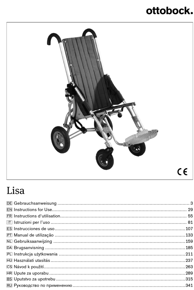
Otto Bock Lisa User manual