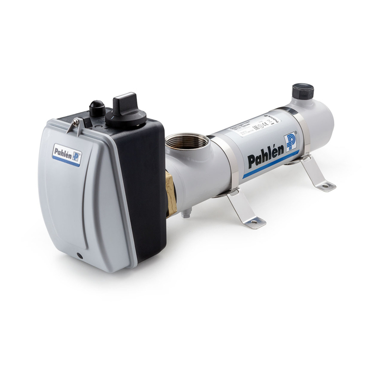
Pahlen Aqua Spa User manual

www.pahlen.com
© Copyright 2007 Pahléns Fabriker AB, Box 728, SE-194 27 Upplands Väsby, Sweden
®
Elvärmare
Monteringsanvisning
MA45-01S
2015
Montera värmaren liggande enligt ritning, så att den alltid är helt vattenfylld. Värmaren kan placeras stående, om den
monteras så att vattnet i rören står minst 50 cm över värmaren.
Om värmaren placeras mot brännbart material, skall en brandsäker skiva eller liknande placeras mellan värmare och vägg.
Skivan skall täcka 10 cm utanför värmarens yttre mått. Värmaren får ej övertäckas.
Värmaren skall elektriskt anslutas över en eller två kontaktorer, beroende på värmarens utförande, se kopplingsschema.
Den elektriska installationen skall utföras så att värmaren ej kan slås på utan att anläggningens lterpump är i funktion
(manöverströmmen till värmarens kontaktor styrs över pumpens motorskydd).
Värmaren skall installeras på returledningen till poolen efter ltret. Installera ej avstängningsventil mellan värmaren och
poolen. Om ventil erfordras, installera en backventil.
Dosering av klor, syra eller liknande måste göras efter värmaren för att undvika korrosion.
1. Efter färdig rörinstallation anslutes värmaren elektriskt enligt kopplingsschema.
2. Viktigt! Om värmaren är utrustad med ödesvakt, är denna för max. 80W belastning eller för max. 1,25A vid 230V
nätspänning. Om belastningen är högre, måste ett hjälprelä installeras.
3. Starta pumpen till poolvattencirkulationen. Kontrollera att vattnet cirkulerar normalt i anläggningen innan strömmen
till värmaren slås till. Funktionsprova värmaren genom att vrida termostatratten fram och tillbaka och kontrollera att
termostatens kontaktor slår till och från. Ställ sedan in önskad pooltemperatur. Eventuell ödesvakt eller pressostat
kontrolleras genom att stänga av ödet genom värmaren med en avstängningsventil och kontrollera att kontaktorn slår
ifrån. Värmaren skall nu värma poolvattnet till önskad temperatur. Om värmaren inte startar, vidtag följande åtgärder:
a) Kontrollera säkringarna.
b) Överhettningsskyddet har löst ut: Tryck in återställningsknappen i kopplingsboxen.
c) Eventuell pressostat är ej sluten: Pressostaten är förinställd på 0,2 bar. Om inte rätt tryck uppnås, skall retur-
ledningen till poolen strypas något för att öka mottrycket i returledningen. Värmaren fungerar ej, om mottrycket i
poolcirkulationssystemet är felaktigt. Pressostaten ansluts på plint 1 och 3.
d) Eventuell ödesvakt är förinställd på ett minimiöde av 45 l/min. Kontrollera att pilens riktning på ödesvakten
överensstämmer med vattnets ödesriktning. Om inte, vrid ödesvakten 180°.
e) Ställ om termostaten till en högre temperatur.
Vid frysrisk skall installationen vara så utförd att värmaren kan tappas på allt vatten.
Den elektriska installationen får endast utföras av behörig elinstallatör.
Vid backspolning och rengöring av ltret skall strömmen till värmaren slås ifrån.
Viktigt!
Vattnet får ej vara aggressivt.
Värmaren får ej användas i saltvatten eller i pooler med klormaskin/saltgenerator.
Följ nedanstående anvisningar:
Klorhalt:
Klorid(salt)halt:
pH-värde:
Alkalinitet:
Kalciumhårdhet:
Max temperatur:
Max tryck:
Minimiöde:
Max tryck vid pressostat:
max 3 mg/l (ppm)
max 150 mg /l
7,2 - 7,6
60-120 mg/l (ppm)
100-300 mg/l (ppm)
110°C
10 bar
20 l/min.
2 bar

www.pahlen.com
© Copyright 2007 Pahléns Fabriker AB, Box 728, SE-194 27 Upplands Väsby, Sweden
®
Flödesvakt
Pressostat
Anslutning till plint 1 och 3
Vit
Blå Blå
Röd
Vit Röd
Påslag
Över-
hettningsskydd
Termostat
Pressostat
eller
ödesvakt
Motorskydd
Påslag
Pressostat
eller
ödesvakt
Motorskydd
Termostat
3-pol över-
hettningsskydd
Elvärmare
Monteringsanvisning
MA45-01S
2015

www.pahlen.com
© Copyright 2007 Pahléns Fabriker AB, Box 728, SE-194 27 Upplands Väsby, Sweden
Electric heater MA45-01E
2015
Installation instruction
Install the electric heater as illustrated in a horizontal position, so that it is ooded at all times. The heater may be installed
in a vertical position as long as there is a positive pressure of water in the tubes of at least 50 cm.
If the heater is mounted against inammable material the installer must place a gypsam wallboard between the heater and
the inammable wall. The board must protrude a minimum of 10 cm outside the body of the heater. The heater must not
be covered, enclosed in or placed near inammable material.
The heater shall be connected over one or two contactors, depending on type of heater, see wiring diagram.
The heater shall be installed in such way that it can not be activated if the lter pump is not working (sufcient ow), i.e.
the power supply to the contactor must be guided over the motor protection of the pump. The electric heater must be
installed on the return pipe to the pool after the lter. Do not install a gate valve between heater and pool. If a valve is
required, install a check valve.
Dosage of chlorine, acid or similar, must be done after the heater to avoid corrosion.
1. When the pipe installation is made, connect the heater electrically according to wiring diagram.
2. Important! If the heater is equipped with a ow switch, the max. load is 80W or max. 1,25A at 230V main voltage.
If the load is higher an auxiliary relay must be installed.
3. Start the pump to the pool water circulation. Check that the water circulation is normal before the heater is turned on.
Test the heater by turning the thermostat knob back and forth and check that the contactor of the thermostat turns on
and off. Set desired pool temperature. Check any ow switch or pressure switch by turning off the ow through the
heater with a gate valve and control that the contactor is beeing deenergized. The heater will now heat the pool water
to desired temperature. If the heater does not start:
a) Check the fuses.
b) The overheating limit control is released: Press the reset button in the connection box.
c) Any pressure switch is not closed: The pressure switch is pre-installed on 0,2 bar. If a correct pressure is not
attainable, the return pipe to the pool shall be somewhat cut down in order to increase the back pressure in the
return pipe. The heater will not work, if the back pressure in the circulation system is incorrect. The pressure
switch is connected to terminal block 1 and 3.
d) Any ow switch is pre-set at a minimum ow of 45 l/min. Check that the direction of the arrow on the ow switch
agree to the direction of the water ow. If not, turn the ow switch 180°.
e) Reset the thermostat to a higher temperature.
In case of climates with sub-zero temperatures the heater must be installed so that it can be emptied.
The electric installation must be done by a licenced electrician.
When back-washing and cleaning the lter, the power to the heater must be turned off.
Important!
The water must not be aggressive.
The heater must not be used in salt water or in pools where a salt chlorinator is used.
Follow the instructions stated below:
Chlorine content:
Chloride content:
pH-value:
Alkalinity:
Calcium hardness:
Max temperature:
Max pressure:
Minimum ow:
Max pressure on pressure switch:
max 3 mg/l (ppm)
max 150 mg /l
7,2 - 7,6
60-120 mg/l (ppm)
100-300 mg/l (ppm)
110°C
10 bar
20 l/min.
2 bar

www.pahlen.com
© Copyright 2007 Pahléns Fabriker AB, Box 728, SE-194 27 Upplands Väsby, Sweden
Flow switch
Pressure switch
Connection to terminal block 1 and 3
White
Blue Blue
Red
White Red
On/Off
Overheating
limit control
Thermostat
Pressure
switch or ow
swtich
Motor protection
On/Off
Pressure
switch or
ow swtich
Motor protection
Thermostat
Three-pole
overheating
limit control
Electric heater MA45-01E
2015
Installation instruction

www.pahlen.com
© Copyright 2007 Pahléns Fabriker AB, Box 728, SE-194 27 Upplands Väsby, Sweden
Elektro-Durchlauferhitzer MA45-01T
2015
Installationsanweisung
Der Elektro-Heizer gemäss beiliegender Skizze liegend montieren, um sicherzustellen, dass er immer vollständig mit
Wasser gefüllt ist. Der Elektro-Heizer kann stehend installiert werden, wenn das Wasser im Rohr dabei mindestens 50 cm
oberhalb des Elektro-Heizers steht.
Falls der Elektro-Heizer an einer brennbaren Oberäche angebracht wird, muss zwischen Elektro-Heizer und Wand eine
Platte aus feuerfestem Material oder ähnliches vorgesehen werden. Diese Platte muss an allen Seiten mindestens 10 cm
über den Elektro-Heizer überstehen. Der Elektro-Heizer darf nicht abgedeckt werden.
Der elektrische Anschluss des Elektro-Heizers erfolgt je nach Ausführung über einen oder zwei Schütze.
Der elektrische Anschluss muss so ausgeführt sein, dass der Elektro-Heizer nicht eingeschaltet werden kann, solange die
Filter-Umwälzpumpe der Anlage nicht in Betrieb ist. Dazu ist der Schaltstrom für den Schütz bzw. die Schütze des Elektro-
Heizers über den Motorschutz der Umwälzpumpe zu leiten.
Der Elektro-Heizer ist in der Rücklaueitung zum Pool hinter dem Filter zu installieren. Zwischen Elektro-Heizer und Pool
darf sich kein Absperrventil benden. Falls ein Ventil erforderlich ist, kann ein Rückschlagventil eingebaut werden.
Um Korrosion zu vermeiden, muss die Zugabe von Chlor, Säuren oder ähnlichen chemischen Zusätzen in Durchuss-
richtung hinter dem Elektro-Heizer erfolgen.
1. Nach Abschluss der Rohrinstallation ist der Elektro-Heizer gemäss Schaltplan elektrisch anzuschliessen.
2. Wichtiger Hinweis! Wenn der Elektro-Heizer mit einem Durchusswächter ausgestattet ist, ist dieser auf eine Leistung
von maximal 80 W beziehungsweise auf eine Stromstärke von maximal 1,25 A bei 230 V Netzspannung ausgelegt. Bei
einer höheren Leistung/Stromstärke muss ein zusätzliches Relais installiert werden.
3. Umwälzpumpe für den Pool einschalten. Vor dem Einschalten des Elektro-Heizers überprüfen, ob das Wasser richtig
durch die gesamte Anlage gepumpt wird. Um die Funktion des Elektro-Heizers zu überprüfen, das Einstellrad des
Thermostaten vor und zurückdrehen und prüfen, ob der Schütz des Thermostats ein- und ausschaltet. Dann die
gewünschte Pooltemperatur einstellen. Um gegebenenfalls die Funktion des Durchusswächters oder des Pressostaten
zu überprüfen, den Wasserdurchuss durch den Elektro-Heizer mit einem Absperrventil blockieren und überprüfen, ob
der Schütz abschaltet. Wenn alle Komponenten einwandfrei arbeiten, heizt der Elektro-Heizer das Wasser im Pool jetzt
auf die gewünschte Temperatur auf. Falls sich der Elektro-Heizer nicht einschaltet, folgende Punkte überprüfen:
a) Ist eine Sicherung durchgeschmolzen bzw. ausgelöst?
b) Hat der Überhitzungsschutz ausgelöst? In diesem Fall die Rückstelltaste in der Anschlussdose betätigen.
c) Hat der Pressostat (sofern vorhanden) nicht geschlossen? Der Pressostat ist auf einen Druck von 0,2 bar vor-
eingestellt. Falls dieser Druck unter normalen Betriebsbedingungen nicht erreicht wird, muss die Rücklaueitung
zum Pool etwas verengt werden, um den Gegendruck in der Rücklaueitung zu erhöhen. Bei unzureichendem
Druck in der Rücklaueitung funktionert der Elektro-Heizer nicht. Der Pressostat ist an die Klemmen 1 und 3
anzuschliessen.
d) Der Durchusswächter ist auf eine Mindest-Durchussmenge von 45 l/min voreingestellt.
Sicherstellen, dass die durch einen Pfeil auf dem Gehäuse gekennzeichnete Durchussrichtung des Durchuss-
wächters mit der Fliessrichtung des Wassers übereinstimmt. Falls der Durchusswächter falsch herum montiert ist,
um 180° verdreht neu installieren.
e) Der Thermostat auf eine höhere Temperatur einstellen.
Bei Anlagen, bei denen Frostgefahr besteht, muss der Elektro-Heizer so installiert werden, dass das Wasser vollkommen
aus dem Elektro-Heizer abgelassen werden kann.
Sämtliche Elektroinstallationsarbeiten dürfen ausschliesslich von Elektriker ausgeführt werden.
Beim Gegenspülen oder bei der Reinigung des Filters ist der Elektro-Heizer abzuschalten.
Wichtiger Hinweis!
Das verwendete Wasser darf nicht aggressiv sein. Dieser Elektro-Heizer ist nicht für den Einsatz in Salzwasser oder in
Pools mit Chlormaschine/Salzgenerator geeignet.
Die folgende Werte sollen eingehalten werden:
Chlorgehalt:
Chloridgehalt:
pH-Wert:
Alkalinität:
Kalziumhärte:
Höchsttemperatur:
Höchstdruck:
Mindest-Durchussmenge:
Höchstdruck am Pressostat:
maximal 3 mg/l (ppm)
maximal 150 mg /l
7,2 - 7,6
60-120 mg/l (ppm)
100-300 mg/l (ppm)
110°C
10 bar
20 l/min.
2 bar
Other manuals for Aqua Spa
3
This manual suits for next models
6
Table of contents
Languages:
Other Pahlen Electric Heater manuals

Pahlen
Pahlen Aqua compact User manual

Pahlen
Pahlen MidiHeat EHA User manual

Pahlen
Pahlen Aqua SPA 141650 User manual

Pahlen
Pahlen Aqua Spa User manual

Pahlen
Pahlen Maxi Heat User manual

Pahlen
Pahlen Compact Operator's manual

Pahlen
Pahlen Aqua compact Incoloy 141600 User manual

Pahlen
Pahlen Aqua Compact Standart User manual

Pahlen
Pahlen Aqua HL User manual

Pahlen
Pahlen Aqua Spa User manual