8
Jet Swim 2000
MA30-02 GB
ENGLISH
This document and its contents are the exclusive
property of Pahléns and may not be copied,
reproduced, transmitted or communicated to a third
party, or used for any purpose without written permission.
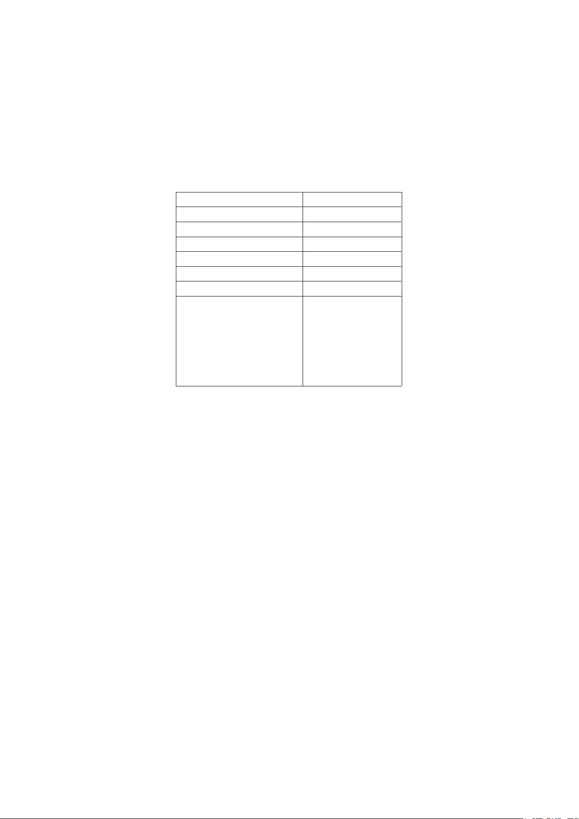
Art.no.
Rev.no.
Scale
Designed by: Approved by:
Revised by: Date
Drawn by: Date
Drawing number
Assembly drawing no.
Surface treatment
part of ISO 2768-1
The tolerance class in accordance with this
E
Box 728, SE-194 27 Upplands Väsby, Sweden
Phone +46 8 59411050, Fax +46 8 59086880
1302000-01
RJ 2017-01-11
Grundsats 2017
Jet Swim 2000 M12666 0
C
A
+
_
On/Off
Jet Swim 2000 (Front panel)
M10199-2
130507 OA
_
+
+
_
On/Off
Jet Swim 2000 (Front panel)
M10199-2
130507 OA
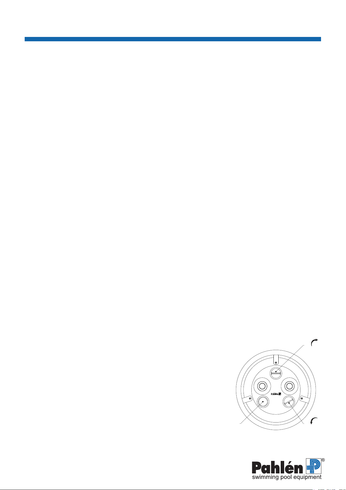
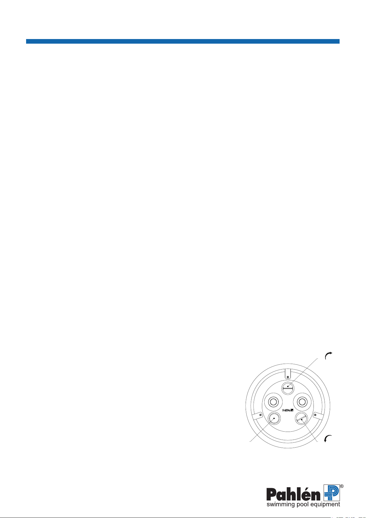
Figure 1.
Front Jet Swim 2000
On/O Air
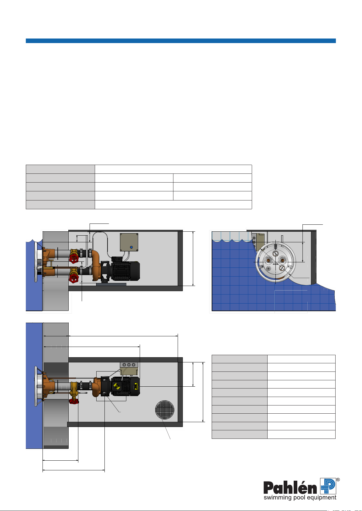
Installation - Liner pool
1. Remove the stainless steel front and cut out the pool wall according to the hole pattern. The centre of the Jet Swim housing
shall rest 200–230 mm under the surface of the water.
2. Install the Jet Swim housing in the wall of the pool. Then attach the self-fastening washer on the bronze part.
3. Put the pool liner in place. Make sure that the two protruding Jet outlets do not damage / get caught on the pool liner.
Fill the pool with water. When the water reaches about 5 cm below the Jet Swim housing, the ange and rubber washer are
screwed in place against it.
Cut away the pool liner from the inside of the ange and then install the stainless steel front.
4. Connect the hose for the air admixture and tighten the hose clamp. Then attach the outlet onto the hose 100 mm above the
surface of the water behind the pool wall.
5. Connect the starting hose to the pump’s contactor panel.
N.B.! The starting hose must be set in a loop 150–200 mm above the surface of the water.
6. Connect the pipes and valves to the pump according to the image (page 6). The threads are sealed with thread seal tape.
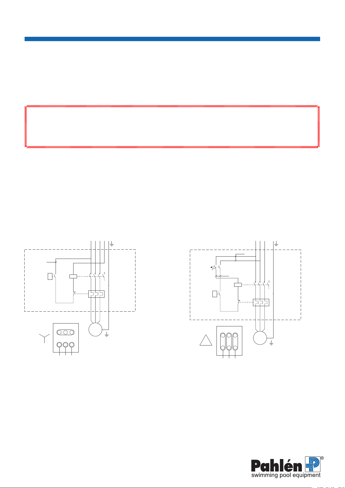
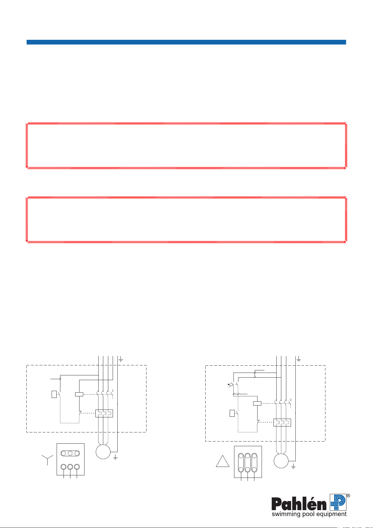
7. The electrical connection must be made by an authorised electrician and be equipped with a residual current device.
8. Make sure that the pump’s direction of rotations is consistent with the ow of the system. Open the valves. Completely ll the
pump with water before starting it with the push-button( A g.1) on the stainless steel front.
9. The ow can be controlled with the knob (B g. 1) above the outlet nozzles. Air can be added to the water streams using the
knob (C g. 1) below the outlet nozzles.
Flow
Start
The pump must be lled with water prior to starting. Never run the pump dry, as that
can damage the parts inside. Make sure that all the valves to and from the pump are
open prior to starting.
The Jet Swim pump is started and stopped by air impulse via the pushbutton (A)
on the stainless steel front; see gure 1.
The ow of water can be controlled using the knob (B) above the outlet nozzle;
see gure 1.
Air can be added to the water streams using the knob (C) below the outlet nozzles;
see gure 1.
Please note
Upon risk of freezing: close the valves, remove and drain the pump of all water.
Lower the water level to approximately 10 cm under the Jet Swim housing in
order to avoid freezing damage.
The pump should be store indoors in the winter.
When restarting: Check the condition of the starting button and the hoses.
Installation - Concrete pool
1. Remove the stainless steel front and install the Jet Swim housing in the form. The nished pool wall shall be in line with the
ange on the bronze housing. The centre of the Jet Swim housing shall be located 200–230 mm under the water surface.
2. Install the leak ange for suction and pressure connections as well as the leak ange for the air admixture and starting hose
(protective pipe), prior to casting. The threads are sealed with thread seal tape.
3. After the casting (and any tiling) the stainless steel front is installed.
4. Connect the hose for the air admixture and tighten the hose clamp. Then attach the outlet onto the hose 100 mm above the
surface of the water behind the pool wall.
5. Connect the starting hose to the pump’s contactor panel.
N.B.! The starting hose must be set in a loop 150–200 mm above the surface of the water.
6. Connect the pipes and valves to the pump according to the image (page 6). The threads are sealed with thread seal tape.
7. The electrical connection must be made by an authorised electrician and be equipped with a residual current device.
8. Make sure that the pump’s direction of rotations is consistent with the ow of the system. Open the valves. Completely ll the
pump with water before starting it with the push-button( A g.1) on the stainless steel front.
9. The ow can be controlled with the knob (B g. 1 ) above the outlet nozzles.
Air can be added to the water streams using the knob (C g. 1) below the outlet nozzles.
Installation - Concrete pool with liner
Install according to point 1 and 2 “Installation - concrete pool” and point 3–9 “Installation - liner pool”.