Pahlen Jet Swim Motion User manual

9
Jet Swim Motion
MA30-09 GB
ENGLISH
4
21
Jet Swim 1200
5
4
21
Jet Swim 1200
It is important to read through this manual carefully in order to ensure the function and useful length of the pool equipment.
Pahlén AB is not responsible for product warranties or damages that occur as a result of faulty installation, improper use or poor
maintenance.
Product Description
Jet Swim Motion is an apparatus use for training, exercise and recreation. It features adjustable jet stream for personal customi-
sation of the water ow and air mixture.
Jet Swim Motion consists of four parts:
Base kit Installation kit Pump kit Control box
1301300 Classic
1301305 Marine
1301310
for thin pool walls
for thick pool walls
,
1301390 400V
Technical Data
Motor .
Volage
Current . . . .
Pump capacity m3h 43 m3h
nclosed protection class IP55
The product is intended for the following water values:
Total chlorine content max . mliter Iron: max . mliter
hloride salt content max mliter Copper: max . mliter
pvalue .. Manganese: max . mliter
Alkalinity mliter ppm Phosphorus: max . mliter
Calcium hardness: mliter ppm Nitrate: max mliter
ccordin to
The product warranty does not apply outside of these values.
CENELEC* members:
Note! The appliance can be used by children from the ae of and above and persons with reduced physical, sensory or
mental capabilities or lack of experience and knowledge, if they have been given supervision or instruction concerning use
of the appliance in a safe way and understand the haards involved. hildren shall not play with the appliance. leanin
and user maintenance shall not be made by children without supervision.
Other countries than CENELEC members (according to IEC):
Note! This appliance is not intendend for use by persons includin children with reduced physical, sensory or mental
capabilities, or lack of experience and knowledge, unless they have been given supervision or instruction concerning the
use of the appliance by a person responsible for their safety. Children should be supervised to ensure that they do not play
with the appliance.
members are ustria, elium, ularia, roatia, the ech epublic, enmar, stonia, inland,
ermany, reece, unary, celand, reland, taly atvia, ithuania, ucembour, alta, the etherlands, orway,
Poland, omania, lovaia, lovenia, pain, weden, witerland, Turey and the nited indom.
Safety
The et stream is powerful, which is why one should not be closer than . m from the stream outlet for a protracted period.
People with lon hair should pay careful attention so that their hair does not et stuc in the inlets the perforated openins in
the stainless steel front.
Small children should not be in the pool without supervision, especially not when the Jet Swim device is in operation.
Always inform all the other bathers in the pool before starting the Jet Swim.
Always make sure that the power to the pump is turned o prior to any work, service or maintenance of the pump begins.

10
Jet Swim Motion
MA30-09 GB
ENGLISH
This document and its contents are the exclusive
property of Pahléns and may not be copied,
reproduced, transmitted or communicated to a third
party, or used for any purpose without written permission.
min
min
min
vlopp
Drain
Dimensions
easurements within parentheses pertain to item no. for thin pool walls with liner
framework of wood, metal or plastic
.

11
Jet Swim Motion
MA30-09 GB
ENGLISH
rt.no.
ev.no.
cale
esined by pproved by
evised by ate
rawn by ate
rawin number
ssembly drawin no.
urface treatment
part of
The tolerance class in accordance with this
ox , pplands sby, weden
Phone , ax
et swim motion tunnvi sprnsiss
This document and its contents are the exclusive
property of Pahléns and may not be copied,
reproduced, transmitted or communicated to a third
party, or used for any purpose without written permission.
This document and its contents are the exclusive
property of Pahléns and may not be copied,
reproduced, transmitted or communicated to a third
party, or used for any purpose without written permission.
rt.no.
ev.no.
cale
esined by pproved by
evised by ate
rawn by ate
rawin number
ssembly drawin no.
urface treatment
part of
The tolerance class in accordance with this
ox , pplands sby, weden
Phone , ax
m
isch vetsad
A A
B
x
Installation
The pump section is installed on a stable surface in a dry area. ae sure that the area is well venti-
lated and is euipped with a drain in order to prevent oodin.
All installation of stainless steel parts shall be done using tools solely intended for such material
in order to maintain its corrosion-resistance. All screws should be lubricated with Molykote®
included. The recess must be installed horiontally with the buttons on the lower side. The ede
of the ane on the recess has a small acs that aid in marin and checin the horiontal
placement, see Fig 1.
See the Section entitled “Dimensions” for installation measures, placements etc.
N.B.!
The starting hose must be set in a loop 150-200 mm above the surface of the water.
Never run the pump dry. This will damage the axle seal.
Installation in thin pool wall with liner
(wood, sheet metal, plastic, etc.)
1. ae an mm hole in the pool wall. se the niche as the template for six mm holes see .
. ttach the niche see i in the pool wall with the included screws.
3. ttach the selfadhesive aset onto the niches ane.
4. Install the pool liner with water up to 5 cm under the house.
5. crew the clampin rin and the rubber aset in place aainst the niche, m in torue. The screws must be lubricated.
. Cut away the pool liner against the inside of the clamping ring.
. nstall the intae rate and the stainlesssteel front. These screws must be lubricated.
. Connect the hose for the air admixture and tighten the hose clamp.
Attach the other opening of the hose 100 mm above the surface of the water behind the pool wall.
9. onnect the start hose with a loo at least mm over the surface of the water to the control box.
10. Connect pipes and valves to the pump, see Figure 1. All threads must be tightened with thread tape.
11. lectrical connection shall be made by an authorised electrician.
Sample image: wooden frame with liner
1. Niche
. crew
3. Nut
. asher
5. Self-adhesive gasket
. aset
. lampin rin
. crew
9. Inlet grate
10. Screw
11. Front
. crew
13. Pool framework
. all coverin
15. Liner
Figure 1.
Recess seen from the front.
UP

Jet Swim Motion
MA30-09 GB
ENGLISH
rt.no.
ev.no.
cale
esined by pproved by
evised by ate
rawn by ate
rawin number
ssembly drawin no.
urface treatment
part of
The tolerance class in accordance with this
ox , pplands sby, weden
Phone , ax
et swim motion mursten sprnsiss
This document and its contents are the exclusive
property of Pahléns and may not be copied,
reproduced, transmitted or communicated to a third
party, or used for any purpose without written permission.
rt.no.
ev.no.
cale
esined by pproved by
evised by ate
rawn by ate
rawin number
ssembly drawin no.
urface treatment
part of
The tolerance class in accordance with this
ox , pplands sby, weden
Phone , ax
et swim motion beton sprnsiss
This document and its contents are the exclusive
property of Pahléns and may not be copied,
reproduced, transmitted or communicated to a third
party, or used for any purpose without written permission.
This document and its contents are the exclusive
property of Pahléns and may not be copied,
reproduced, transmitted or communicated to a third
party, or used for any purpose without written permission.
rt.no.
ev.no.
cale
esined by pproved by
evised by ate
rawn by ate
rawin number
ssembly drawin no.
urface treatment
part of
The tolerance class in accordance with this
ox , pplands sby, weden
Phone , ax
m
isch vetsad
A A
Concrete pool without liner
Concrete pool with tiles/mosaic: efore assemblin in the form, the nole and the parts be-
hind them are removed. spacer and an extra aset are added in the order as shown
in the imae above when the nole is put bac in place T mouldin the stud bolts in the
recess are lubricated. The nuts are tihtened to . m.
Painted concrete pools: Do not require the above step.
1. ssembly the recess in the form, see iure . The ane on the niche should be in line
with the nished pool wall.
N.B.! Reinforcement present must not be closer than 50 mm from stainless steel material.
. Connect the start hose to the niche.
3. Attach all socketing pipes in the niche prior to moulding. All threads must be tightened with
thread tape.
4. ould. hen the concrete has burned and any tilin is completed, install the tension rin and
front with intake grates, tighten the screws to a torque of 5 Nm.
these screws must be lubricated.
5. Connect the hose for the air admixture and tighten the hose clamp.
Attach the opening of the hose 100 mm above the surface of the water, behind the pool wall.
. Connect the start hose
with a loo at least mm over the surface of the water
to the control box.
. onnect pipes and valves to the pump. Threads are sealed with thread seal tape.
Thick pool wall with liner
(Masonry block, thermoblock, concrete etc.)
N.B.! Any reinforcement present must not be closer than 50 mm from stainless steel material.
The pool wall must be done bein polished before any constituent parts are installed.
1. ae a hole in the pool wallform and attach the niche, see iure .
The ane on the niche should be in line with the nished pool wall.
. Connect the start hose to the niche.
3. Attach all socketing pipes in the recess. All threads must be tightened with thread tape.
4. ast or else bric up with masonry stones.
5. ttach the selfadhesive aset onto the niches ane.
. Install the pool liner with water up to 5 cm under the house.
. crew the clampin rin and the rubber aset in place aainst the ane of the niche,
5 Nm in torque, the screws must be lubricated.
. Cut away the pool liner against the inside of the clamping ring.
9. nstall the intae rate and the front these screws must be lubricated.
10. Connect the hose for the air admixture and tighten the hose clamp. Attach the other opening of
the hose 100 mm above the surface of the water, behind the pool wall.
11. Connect the start hose
with a loop at least mm over the surface of the water
to the control box.
. Connect pipes and valves to the pump. All threads must be tightened with thread tape.
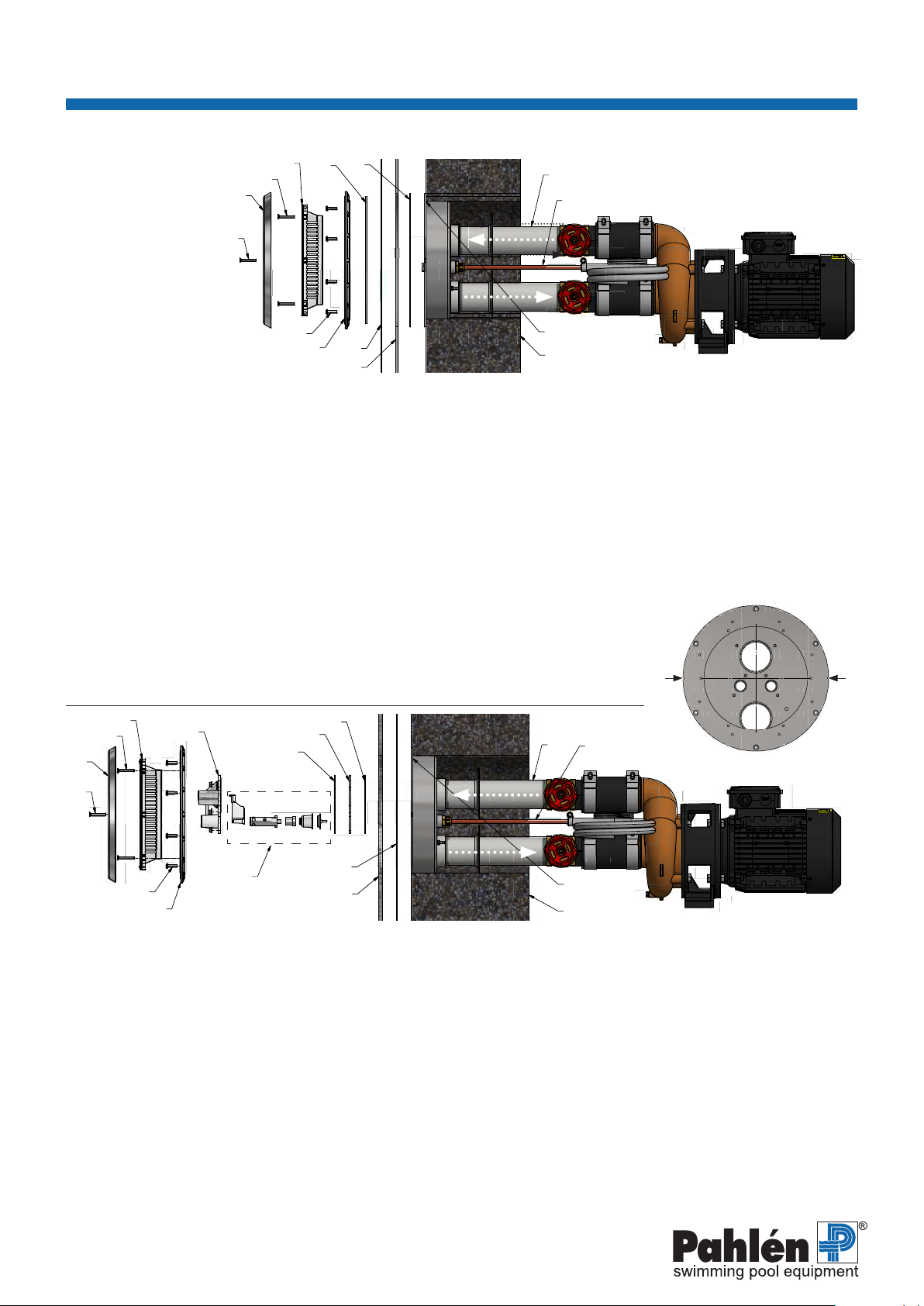
Installation in Thick Pool Walls
Sample image:
concrete without liner
1. Niche
. ocetin pipes, water
. ocetin pipes, airstart
4. —
5. —
. lampin rin
. crew
. ntae rate
9. Screw
10. Front
11. Screw
. Pool framewor
13. Polish
. Tiletile cement
15. Gasket
. pacer
. Parts of the nole
. ole
Figure 1.2
Recess seen from the front.
UP
Sample image:
masonry block with liner
1. Niche
. ocetin pipes, water
. ocetin pipes, airstart
4. Self-adhesive gasket
5. Gasket
. lampin rin
. crew
. ntae rate
9. Screw
10. Front
11. Screw
. Pool frame bric
. all coverin
14. Liner

13
Jet Swim Motion
MA30-09 GB
ENGLISH
This document and its contents are the exclusive
property of Pahléns and may not be copied,
reproduced, transmitted or communicated to a third
party, or used for any purpose without written permission.
rt.no.
ev.no.
cale
esined by pproved by
evised by ate
rawn by ate
rawin number
ssembly drawin no.
urface treatment
part of
The tolerance class in accordance with this
ox , pplands sby, weden
Phone , ax
lassic
rundsats et wim otion
A
vP
B
uftusterin
U1
V1
W1
2
4
6
2
4
6
14 13
1
3
5
1
K1
2,5~D
B1
M1
P
NO COM
F1
3
5
1
3
5
A1
A1A29695
L1
L2
L3
N
M
U1
V1
W1
2
4
6
2
4
6
14 13
1
3
5
1
K1
1,5~D
2,5~D
B1
F2
M1
P
NO COM
F1
3
5
1
3
5
A1A2
2
4
1
3
9695
L1
L2
L3
M
iure . ront lassic
A
On/O
B
Air adjustment
Start
The pump must be lled with water prior to startin. Never run the pump dry, as that can damage the parts inside.
1. Make sure that the pump’s direction of rotations is consistent with the arrow
on the motor’s fan cover.
. Open the valves.
3. Make sure that all the valves to and from the pump are open.
ae sure that the pump is completely lled with water before it is started.
4. Start the pump.
Electrical Installation
All electrical connections shall be made by an authorised electrician.
The device shall be preceded by a residual current device with a maximum breain current of m. The pump motor is
connected via the control panel for Jet Swim Motion, see the circuit diagram. Check the rating plate on the pump motor for the
correct connection on the closing link.
ae sure that the pump motor has been connected in the correct direction of rotation see the rotation direction arrows on the
pump motors fan casin. The wron direction
can damage the pump.
N.B.! The pump must never be started without being lled with water.
Make sure that the motor guard in the control panel is set according to the rated current; see pump’s the rating plate.
Electrical Connection Diagram
3~400V 3~230V
Operation
1. tart the et streams with the push button ure .
. The air mixture can be adusted with the dial
3. Turn o the et streams with the push button ure .
N.B!
hen there is a ris of freein, close the valves, remove and drain the pump of all water. The pump should be stored indoors.
ower the water level to approximately cm under the et wim housin in order to avoid freein damae.
Pressure
switch
Connector
nine
circuit relay
P
Circuit
breaker
Connector
nine
circuit relay
P
Pressure
switch
Other manuals for Jet Swim Motion
1
Table of contents
Other Pahlen Swimming Pool Pump manuals
Popular Swimming Pool Pump manuals by other brands

Swim & Fun
Swim & Fun SMPC-200 user manual

Hayward
Hayward Super Pump VS SP2603VSP owner's manual

Harmopool
Harmopool QBIC instruction manual

Clarke
Clarke 7175031 Operation & maintenance instructions

Hayward
Hayward TriStar Waterfall owner's manual

Hayward
Hayward MaxFlo XL-SP2300 Series Installation and operating instruction manual