Palmgren 80150 User manual

operat ng manual & parts l st 80150
12″
BENCH MODEL DRILL PRESS
Read carefully and follow all safety rules and operating instructions before
first use of this product.
35285.09-1011

DESCRIPTION
Palmgren Drill Presses feature a heavy cast iron base, column collar,
work table and head. Work table height is adjustable using rack
and pinion. Table can be tilted 45° both right and left, and rotates
360° on a vertical axis. Work table surface is precision ground and
features T-slots for secure, accurate mounting of workpiece and
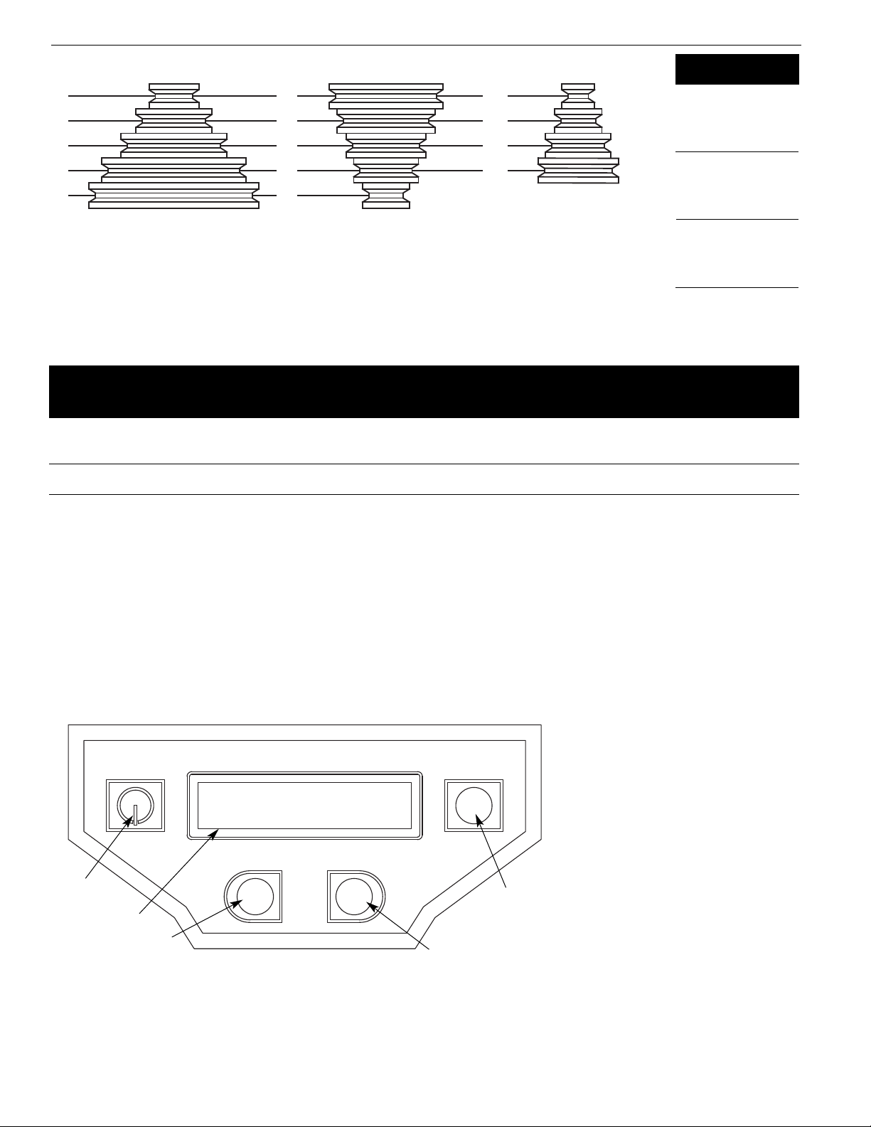
also a coolant trough. Digital readout displays spindle depth and
RPM. Other features of the Palmgren drill press are an enclosed ball
bearing quill assembly, quick belt change and tension mechanism,
positive quick-adjust feed depth stop and a 1
⁄
3P, 1725 RPM
motor. Chuck is included.
Palmgren drill presses are ideal for use in home shops, mainte-
nance shops and light industrial applications. Spindle speeds are
adjustable for drilling steel, cast iron, aluminum, wood and plastic.
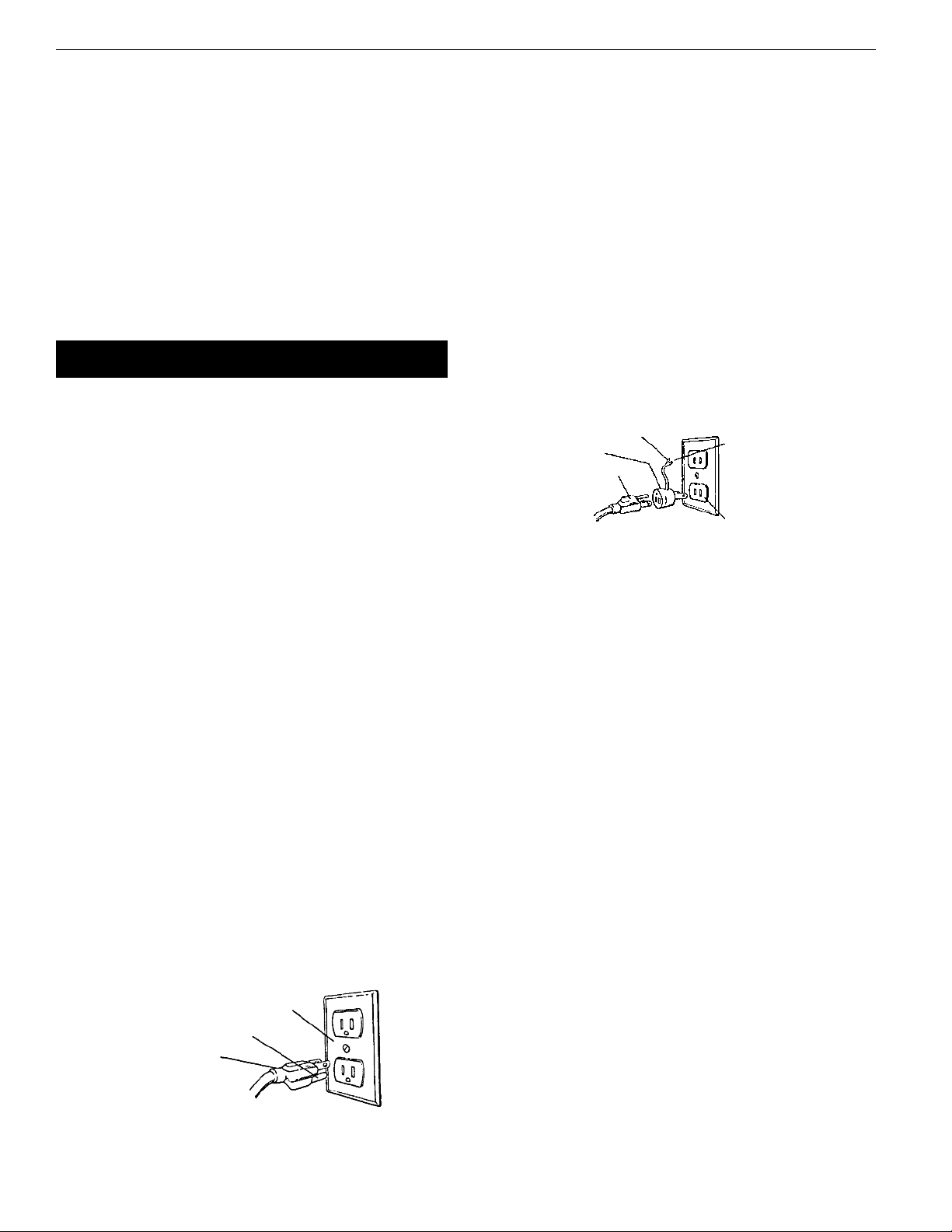
UNPACKING
Refer to Figure 1.
WAR I G: Be careful not to touch overhead power lines, piping,
lighting, etc., if lifting equipment is used. Drill press weighs up to
130 lbs, proper tools, equipment and qualified personnel should be
employed in all phases of unpacking and installation.
Crates should be handled with care to avoid damage from drop-
ping, bumping, etc. Store and unpack crates with correct side up.
After uncrating drill press, inspect carefully for any damage that
may have occurred during transit. Check for loose, missing or dam-
aged parts. If any damage or loss has occurred, claim must be filed
with carrier immediately. Check for completeness. Immediately
report missing parts to dealer.
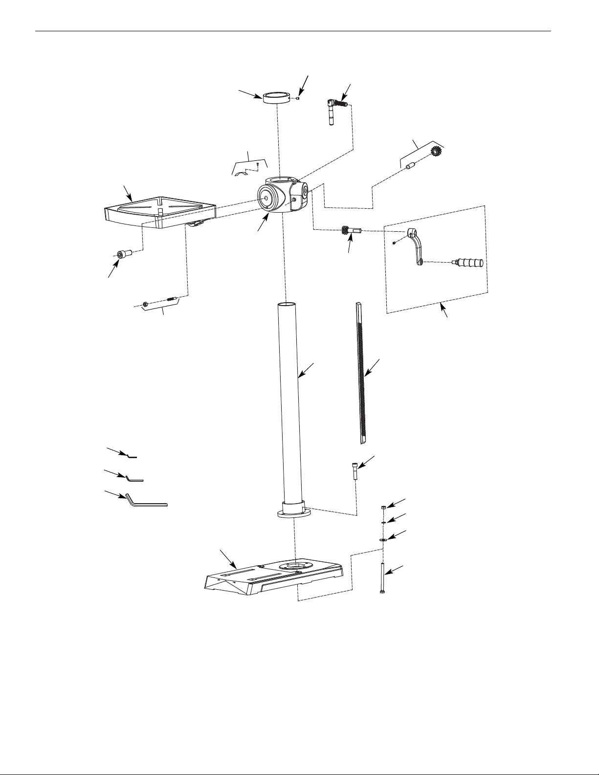
Drill press is shipped unassembled. Locate and identify the follow-
ing assemblies and loose parts:
A ead Assembly
B Table Assembly
C Base
D Column Assembly
E Table andle Assembly
F Table Locking andle
G Drill Chuck with Key
Worm Gear
I Feed andle Grip Assembly
J Feed andle (2)
K M8 x 30 Socket ead Bolt (4)
L M8 x 125 ex ead Bolt with Washers and ex Nuts (2)
M 3, 4 and 6mm ex Wrench
IMPORTA T: The tool has been coated with a protective coating.
In order to ensure proper fit and operation the coating must be
removed. Remove coating with mild solvents such as mineral spir-
its and a soft cloth. Nonflam mable solvents are recommended.
After cleaning, cover all exposed surfaces with a light coating of oil.
Paste wax is recommended for table top.
CAUTIO : Never use highly volatile solvents. Avoid getting clean-
ing solution on paint as it may tend to deteriorate these finishes.
Use soap and water on painted components.
SPECIFICATIO S
Chuck size . . . . . . . . . . . . . . . . . . . . . . . . . . . . . . . . . . . . . . . . . . . .1
⁄
25-1
⁄
2, JT33
Spindle taper . . . . . . . . . . . . . . . . . . . . . . . . . . . . . . . . . . . . . . . . . . . . . . . .JT33
Spindle travel . . . . . . . . . . . . . . . . . . . . . . . . . . . . . . . . . . . . . . . . . . . . . . . .31
⁄
4”
Quill diameter . . . . . . . . . . . . . . . . . . . . . . . . . . . . . . . . . . . . . . . . . . . . . . .1.58”
Quill collar diameter . . . . . . . . . . . . . . . . . . . . . . . . . . . . . . . .2.165” (55mm)
Column diameter . . . . . . . . . . . . . . . . . . . . . . . . . . . . . . . . . . . . . . . . . . . .2.34”
Speeds . . . . . . . . . . . . . . . . . . . . . . . . . . . . . . . . . . . . . . . . . . . . . . . . . . . . . . . .16
RPM . . . . . . . . . . . . . . . . . . . . . . . . . . . . . . . . . . . . . . . . . . . . . . . . . . . .244-3386
Swing . . . . . . . . . . . . . . . . . . . . . . . . . . . . . . . . . . . . . . . . . . . . . . . . . . . . . .13.25”
Table size . . . . . . . . . . . . . . . . . . . . . . . . . . . . . . . . . . . . . . . . . . . . . . . .8.6 x 9.4”
T-slots (diagonal) . . . . . . . . . . . . . . . . . . . . . . . . . . . . . . . . . . . . . . .4 x 14mm
Base size . . . . . . . . . . . . . . . . . . . . . . . . . . . . . . . . . . . . . . . . . . . . . .93
⁄
4x 161
⁄
2”
Base working surface . . . . . . . . . . . . . . . . . . . . . . . . . . . . . . . . . . .83
⁄
8x 93
⁄
8”
Drilling capacity (cast iron) . . . . . . . . . . . . . . . . . . . . . . . . . . . . . . . . . . . . .1
⁄
2”
Max. distance, spindle to table . . . . . . . . . . . . . . . . . . . . . . . . . . . . . . .163
⁄
4”
Distance, spindle to base . . . . . . . . . . . . . . . . . . . . . . . . . . . . . . . . . . .225
⁄
16”
Overall height . . . . . . . . . . . . . . . . . . . . . . . . . . . . . . . . . . . . . . . . . . . . . .387
⁄
8”
Weight . . . . . . . . . . . . . . . . . . . . . . . . . . . . . . . . . . . . . . . . . . . . . . . . . . . .113 lbs
Shipping weight . . . . . . . . . . . . . . . . . . . . . . . . . . . . . . . . . . . . . . . . . . .123 lbs
Motor . . . . . . . . . . . . . . . . . . . .1/3 P,120 V, 1725 RPM, 6.0 Amps, 60 Z
SAFETY RULES
PROPOSITIO 65 WAR I G: Some dust created by power
sanding, sawing, grinding, drilling and other construction activities
contains chemicals known to the state of California to cause can-
cer, birth defects or other reproductive harm.
Some examples of these chemicals are:
•Lead from lead-based paints.
•Crystalline silica from bricks and cement and other masonry
products.
•Arsenic and chromium from chemically-treated lumber.
Your risk from these exposures vary, depending on how often you
do this type of work. To reduce your exposure to these chemicals:
work in a well ventilated area and work with approved safety
equipment. Always wear OSHA/ IOSH approved, properly fitting
face mask or respirator when using such tools.
Before any work is done, carefully read the cautions listed. Working
safely prevents accidents.
BE PREPARED FOR JOB
•Wear proper apparel. Do not wear loose clothing, gloves, neck-
ties, rings, bracelets or other jewelry which may get caught in
moving parts of machine.
•Wear protective hair covering to contain long hair.
•Wear safety shoes with non-slip soles.
•Wear safety glasses which comply with United States ANSI
Z87.1. Everyday glasses have only impact resistant lenses. They
are NOT safety glasses.
•Wear face mask or dust mask if cutting operation is dusty.
•Be alert and think clearly. Never operate power tools when tired,
intoxicated or when taking medications that cause drowsiness.
2
Palmgren Operating Manual & Parts List 80150
A
B
C
D
E
F
J
G
K
LM
I
Figure 1 – Unpacking

3
WORK AREA SHOULD BE READY FOR JOB
•Keep work area clean. Cluttered work areas and work benches
invite accidents.
•Do not use power tools in dangerous environments. Do not use
power tools in damp or wet locations. Do not expose power
tools to rain.
•Work area should be properly lighted.
•Proper electrical outlet should be available for tool.
Three-prong plug should be plugged directly into properly
grounded, three-prong receptacle.
•Extension cords should have a grounding prong, and the three
wires of the extension cord should be of the correct gauge.
•Keep visitors at a safe distance from work area.
•Keep children out of workplace. Make workshop childproof. Use
padlocks, master switches or remove switch keys to prevent
any unintentional use of power tools.
TOOL SHOULD BE MAI TAI ED
•Always unplug tool prior to inspection.
•Read operating instructions manual for specific maintaining
and adjusting procedures.
•Keep tool lubricated.
•Use sharp cutters and keep the tool clean for safest operation.
•Remove adjusting tools. Form the habit of checking that adjust-
ing tools are removed before turning on the machine.
•Keep all parts in working order. Check to determine that the
guard or other parts will operate properly and perform their
intended function.
•Check for damaged parts. Check for alignment of moving parts,
binding, breakage, mounting and any other condition that may
affect a tool’s operation.
•Damaged parts should be properly repaired or replaced. Do not
perform makeshift repairs. (Use the parts list provided to order
replacement parts.)
K OW HOW TO USE TOOL
•Use the right tool for the job. Do not force tool or attachment
to do a job for which it was not designed.
•Disconnect tool when changing accessories such as bits, cut-
ters and the like.
•Avoid accidental start-up. Make sure switch is in OFF position
before plugging in.
•Do not force tool. It will work most efficiently at the rate for
which it was designed.
•andle workpiece correctly. Secure work with clamps or vise.
Leave hands free to operate machine, Protect hands from
possible injury.
•Never leave a tool running unattended. Turn the power off and
do not leave tool until it comes to a complete stop.
•Do not overreach. Keep proper footing and balance.
•Never stand on tool. Serious injury could occur if tool is tipped
or if cutter is unintentionally contacted.
•Keep hands away from moving parts and cutting surfaces.
•Know your tool. Learn its operation, application and specific
limitations.
•Feed work into a bit or cutter against the direction of rotation
of bit or cutter.
•Turn the machine off if it jams. A cutter jams when it digs too
deeply into the workpiece. (The motor force keeps it stuck in
workpiece.)
•Use recommended accessories. Refer to page 11. Use of
improper accessories may cause risk of injury to persons.
•Clamp workpiece or brace against column to prevent rotation.
•Use recommended speed for drill accessory and workpiece
material.
WAR I G: Think Safety! Safety is a combination of operator com-
mon sense and alertness at all times when drill press is being used.
ASSEMBLY
MOU T COLUM ASSEMBLY TO BASE
Refer to Figure 7.
•Place base (Ref. No. 1) on flat level surface.
•Mount column assembly (Ref. No. 7) to base using four socket
head bolts (Ref. No. 6).
MOU T TABLE
Refer to Figure 7.
•Loosen set screw (Ref. No. 15). Remove rack and rack retaining
ring (Ref. Nos. 8 and 14) from column (Ref. No. 7).
•Place worm gear (Ref. No. 18) into hole of table bracket (Ref. No.
11). Make sure worm gear meshes with pinion gear (Ref. No. 17).
•Place rack inside table bracket assembly with large, unma-
chined portion of rack to the top. Slide rack into slot in bracket
so that teeth of rack engage pinion gear in bracket.
•Slide table assembly with rack over column. Place bottom end
of rack inside beveled edge of column flange.
•Slide rack retaining ring over column with beveled edge down.
Position ring against top of rack so that rack is in beveled edge
of ring. Secure ring with set screw (Ref. No. 15).
•Rotate table assembly around column. Adjust rack retaining
ring as necessary to prevent binding of rack.
•Attach crank handle (Ref. No. 19) to shaft on worm gear, rotate
worm gear to remove slack, and shoulder crank handle against
table bracket. Secure handle with set screw.
•Thread handle (Ref. No. 16) into table bracket assembly. Position
bracket over the center of the base and secure bracket in
position.
MOU T HEAD ASSEMBLY
Refer to Figure 9.
WAR I G: Although compact, the drill press head assembly is
heavy. Two people are required to mount the drill press head
assembly onto the column.
•Slide drill press head assembly onto top of column.
•Position head so that it is centered over base.
•Secure head by tightening the set screws (Ref. No. 24) on the
right side of the head casting.
I STALL QUILL FEED HA DLES
Refer to Figure 8.
Thread the two quill feed handles (Ref. No. 18) securely into pinion
assembly (Ref. No. 17).
I STALL CRA K ARM A D FEED GRIP
Refer to Figure 8.
•Attach crank arm (Ref. No. 20) to pinion (Ref. No. 17) using sock-
et head bolt (Ref. No. 19).
•Thread feed grip (Ref. No. 21) into crank arm and secure with
hex nut.
Palmgren Operating Manual & Parts List 80150

4
I STALL CHUCK
Refer to Figure 8.
•Be sure spindle and chuck tapers are clean and dry. Make sure
quill is completely retracted.
•Use the provided chuck key (Ref. No. 13) to adjust the jaws of
the chuck (Ref. No. 12) until they are recessed inside the drill
chuck body.
•Slide chuck over spindle taper and push chuck onto spindle.
•Tap the end of drill chuck with a rubber or wooden mallet to
seat it into the spindle.
ardware (Two M8 x 125 hex head bolts, M8 lock washers, M8 hex
nuts and four M8 flat washers) has been provided for mounting
the drill press to a wood base plate. This is recommended if you
intend to place the drill press on a mobile base. The minimum rec-
ommended size of the wood base plate is 3/4 x 24 x 24”.
INSTALLATION
Refer to Figures 2 and 3.
MOU T DRILL PRESS
•Drill press must be mounted to flat level surface. Use shims or
machine mounts if necessary. Do not mount drill press in direct
sunlight.
•Be sure to bolt drill press to floor or bench securely to prevent
tipping and minimize vibration.
•Tighten all nuts and bolts that may have loosened during
shipment.
POWER SOURCE
The motor is designed for operation on the voltage an frequency
specified. Normal loads will be handled safely on voltages not
more than 10% above or below the specified voltage.
Running the unit on voltages which are not within the range may
cause overheating and motor burn out. eavy loads require that
the voltage at motor terminals be no less than the voltage speci-
fied.
GROU DI G I STRUCTIO S
WAR I G: Improper connection of equipment grounding con-
ductor can result in the risk of electrical shock. Equipment should
be grounded while in use to protect operator from electrical
shock.
Check with a qualified electrician if grounding instructions are not
understood or if in doubt as to whether the tool is properly
grounded.
This tool is equipped with an approved 3-conductor cord rated up
to 300V and a 3-prong grounding type plug rated at 115V (See
Figure 2) for your protection against shock hazards.
Grounding plug should be plugged directly into a properly
installed and grounded 3-prong grounding-type receptacle, as
shown (Figure 2).
Do not remove or alter grounding prong in any manner. In the
event of a malfunction or breakdown, grounding provides a path
of least resistance for electrical shock.
WAR I G: Do not permit fingers to touch the terminals of plug
when installing or removing from outlet.
Plug must be plugged into matching outlet that is properly
installed and grounded in accordance with all local codes and
ordinances. Do not modify plug provided. If it will not fit in outlet,
have proper outlet installed by a qualified electrician.
Inspect tool cords periodically, and if damaged, have repaired by
an authorized service facility.
Green (or green and yellow) conductor in cord is the grounding
wire. If repair or replacement of the electric cord or plug is neces-
sary, do not connect the green (or green and yellow) wire to a live
terminal.
Where a 2-prong wall receptacle is encountered, it must be
replaced with a properly grounded 3-prong receptacle installed in
accordance with National Electric Code and local codes and ordi-
nances.
WAR I G: This work should be performed by a qualified electrician.
A temporary 3-prong to 2-prong grounding adapter (See Figure 3)
is available for connecting plugs to a two pole outlet if it is
properly grounded.
Do not use a 3-prong to 2-prong grounding adapter unless permit-
ted by local and national codes and ordinances.
(A 3-prong to 2-prong grounding adapter is not permitted in
Canada.) Where permitted, the rigid green tab or terminal on the
side of the adapter must be securely connected to a permanent
electrical ground such as a properly grounded water pipe, a prop-
erly grounded outlet box or a properly grounded wire system.
Many cover plate screws, water pipes and outlet boxes are not
properly grounded. To ensure proper ground, grounding means
must be tested by a qualified electrician.
Palmgren Operating Manual & Parts List 80150
Figure 3 – 2-Prong Receptacle with adapter
Grounding Lug
Adapter
3-Prong Plug
2-Prong Receptacle
Make sure this is
Connected to a known
Grounded Receptacle
Figure 2 – 3-Prong Receptacle
Properly Grounded Outlet
Grounding Prong
3-Prong Plug

EXTE SIO CORDS
•The use of any extension cord will cause some drop in voltage
and loss of power.
•Wires of the extension cord must be of sufficient size to carry
the current and maintain adequate voltage.
•Use the table to determine the minimum wire size (A.W.G.)
extension cord.
•Use only 3-wire extension cords having 3-prong grounding
type plugs and 3-pole receptacles which accept the tool plug.
•If the extension cord is worn, cut, or damaged in any way,
replace it immediately.
EXTE SIO CORD LE GTH (120 VOLTS)
Wire Size . . . . . . . . . . . . . . . . . . . . . . . . . . . . . . . . . . . . . . . . . . . . .A.W.G.
Up to 25 ft. . . . . . . . . . . . . . . . . . . . . . . . . . . . . . . . . . . . . . . . . . . . . . . . . . . . . .18
25-100 ft. . . . . . . . . . . . . . . . . . . . . . . . . . . . . . . . . . . . . . . . . . . . . . . . . . . . . . .16
100-150 ft. . . . . . . . . . . . . . . . . . . . . . . . . . . . . . . . . . . . . . . . . . . . . . . . . . . . . .14
OTE: Using extension cords over 150 ft. long is not recommended.
ELECTRICAL CO ECTIO S
WAR I G: All electrical connections must be performed by a
qualified electrician. Make sure unit is off and disconnected from
power source while motor is mounted, connected, reconnected or
anytime wiring is inspected.
•The motor should be wired for 120 volts and clockwise rotation
as viewed from shaft end of motor.
•A label on the motor describes the possible wiring configura-
tions. There are many different possible combinations, so only
the diagram provided with the motor should be used.
•The power supply to motor is controlled by a push button
switch. Power lines are connected to the quick connect termi-
nals of the switch.
•The green ground line must remain securely fastened to the
motor ground terminal to provide proper grounding.
OPERATION
Refer to Figures 4-9.
WAR I G: Read and understand operating instructions and
parts manual before operating this machine.
CAUTIO : The operation of any power tool can result in foreign
objects being thrown into the eyes, which can result in severe eye
damage. Always wear safety glasses complying with United States
ANSI Z87.1 (shown on package) before commencing power tool
operation.
STARTI G A D STOPPI G THE DRILL PRESS
Refer to Figures 4 and 9.
WAR I G: Be sure drill bit is not in contact with workpiece when
motor is started. Start motor and allow bit to come up to full speed
before drilling.
•The ON/OFF switch (Ref. No. 36) is located on the front of the
head casting.
•To turn saw ON, pull the switch to the up position.
•To turn saw OFF, push the switch to the down position.
The saw can be locked from unauthorized use by locking the
switch. To lock the switch:
•Turn the switch to OFF position and disconnect saw from
power source.
•Pull the key out. The switch cannot be turned on with the key
removed.
OTE: Should the key be removed from the switch at the ON
position, the switch can be turned off but cannot be turned on
again.
•To replace key, slide key into the slot on switch until it snaps.
SPEED ADJUSTME TS
Refer to Figures 5 and 9.
WAR I G: Be sure drill press is turned off and is disconnected
from power source before adjusting speeds.
•To change spindle speed, loosen motor lock knob (Ref. No. 22),
on the right side of the head and push the motor toward front
of drill press. This will loosen the belt and permit relocating the
belt to the desired pulley groove for the required spindle speed
(See Figure 5, page 6).
•After belt has been repositioned, push motor toward rear of
drill press and tighten motor lock knobs.
•Check belt for proper tension and make any final adjustment. A
belt is properly tensioned when light pressure applied to mid-
point of the belt produces about 1/2” deflection.
TABLE ADJUSTME TS
Refer to Figure 7.
•eight adjustments: To adjust table, loosen locking handle (Ref.
No. 16) and turn crank handle (Ref. No. 19) to desired height.
Immediately retighten table bracket locking handle.
•Tilting work table: Loosen table bolt (Ref. No. 10). Remove pin
and nut (Ref. No. 9). To do this, tighten nut until pin slips out
easily. Tilt table to desired angle up to 45° and retighten table
bolt. Reinsert pin and nut when returning the table to 0° posi-
tion.
•To obtain more distance between chuck and table, the work
table can be rotated 180° and base can be used as a work sur-
face. This permits drilling of larger objects.
•Clamp table securely after adjustments have been made.
DEPTH STOP ADJUSTME T
Refer to Figure 8.
To control drilling depth, loosen locking knob (Ref. No. 16) on pin-
ion assembly (Ref. No. 17). Rotate scale so desired depth is indicat-
ed on scale next to the pointer. Tighten locking knob. Use this fea-
ture to drill more than one hole to the same depth.
To control drilling depth, use scale (Ref. No. 14) to adjust to desired
depth.
MOU T DRILL BIT
Refer to Figure 8.
WAR I G: Be sure drill press is turned off and is disconnected
from power source before mounting drill bit.
•Place drill bit in jaws of chuck.
•Tighten chuck with chuck key. Be sure to tighten chuck using
all three positions on chuck body and remove key.
5
Palmgren Operating Manual & Parts List 80150
Switch
Switch Key
Figure 4 – O /OFF Switch

•Use only the self-ejecting chuck key (Ref. No. 13) supplied with
this drill press, or a duplicate key. Use of any other key might
allow start up with the key still in the chuck. An airborne key
could strike the operator and cause injury.
DIGITAL DISPLAY PA EL
Refer to Figure 6.
• Display panel ‘A’ shows the depth of the spindle and spindle
RPM.
• Button ‘B’ turns power on and off to Display ‘A’.
• Button ‘C’: Press once for spindle depth in inches; press again
for spindle depth in mm.
• Button ‘D’: Press to display spindle RPM.
• Button ‘E’ resets display at zero for spindle depth.
6
Palmgren Operating Manual & Parts List 80150
3386
2277
1518
575
383
244
in. mm
5/16 7.9
5/8 15.9
7/8 22.2
11/431.8
15/841.3
2 50.8
in. mm
3/16 4.8
3/8 9.5
1/2 12.7
3/4 19.0
7/8 22.2
1 25.4
in. mm
11/64 4.4
11/32 8.7
15/32 11.9
11/16 17.5
3/4 19.0
——
in. mm
5/32 4.0
5/16 7.9
7/16 11.1
5/8 15.9
13/16 20.6
——
in. mm
7/64 2.8
1/4 6.4
11/32 8.7
1/2 12.7
5/8 15.9
——
in. mm
3/32 2.4
5/32 4.0
1/4 6.4
3/8 9.5
1/2 12.7
——
in. mm
1/16 1.6
1/8 3.2
3/16 4.8
5/16 7.9
7/16 11.1
9/16 14.3
in. mm
1/32 0.8
1/16 1.6
1/8 3.2
1/4 6.4
3/8 9.5
1/2 12.7
RPM Wood Zinc Diecast Alum. & Brass Plastic Cast Iron &
Bronze
Steel - Mild &
Malleable
Steel - Cast &
Med. Carbon
Steel -
Stainless
& Tool
E
D
C
B
A
Z
Y
X
W
5
4
3
2
1
Motor
Spindle
244
357
383
502
560
575
695
789
840
855
1518
1639
1759
2277
2437
3386
A1-5Z
B2-5Z
A1-4Y
C3-5Z
B2-4Y
A1-3X
D4-5Z
C3-4Y
B2-3X
A1-2W
E5-4Y
D4-3X
C3-2W
E5-3X
D4-2W
E5-2W
RPM
Belt
Location
Figure 5 – Spindle Speed Adjustment
Figure 6 – Digital Display Panel
RPM
ZERO
Inch/
mm
A
B
C
D
E
0.000 mm

7
MAINTENANCE
WAR I G: Turn switch off and remove plug from power source
outlet before maintaining or lubricating your drill press
DRIVE BELT
Replace drive belt when worn.
LUBRICATIO
Refer to Figures 7 and 8.
The ball bearings are lubricated at the factory and need no further
lubrication. Using 20wt. non detergent oil, periodically lubricate
the splines (grooves) in the spindle and the rack (teeth on the
quill) as follows:
•Lower quill assembly (Figure 8, Ref. No. 11) all the way down.
•Apply lubricant around the inside of the hole in the spindle
pulley (Figure 8, Ref. No. 2).
•Apply lubricant to rack (teeth) on quill (Figure 8, Ref. No. 24)
while extended below drill press head.
•Apply lubricant to rack and pinion gear (Figure 7, Ref. Nos. 8
and 17) on column and table assembly.
CLEA MOTOR
Frequently blow out any dust that may accumulate inside motor. If
power cord is worn, cut or damaged in any way, have it replaced
immediately.
Palmgren Operating Manual & Parts List 80150

8
SYMPTOM
Spindle does not turn
Noisy spindle
Noisy operation
Bit burns or smokes
Excessive drill runout or wobble
Drill bit binds in workpiece
POSSIBLE CAUSES
1. No power to drill press
2. Defective switch
3. Defective motor
Defective bearings
1. Incorrect belt tension
2. Dry spindle
3. Loose spindle
4. Loose motor pulley
1. Incorrect speed
2. Chips not coming out of table
3. Dull bit
4. Feeding too slow
5. Bit not lubricated
6. Bit running backwards
1. Bent bit
2. Bit not properly installed in chuck
3. Chuck not properly installed
4. Worn spindle bearings
1. Workpiece pinching bit or excessive feed
2. Improper belt tension
3. Workpiece not supported or clamped
properly
CORRECTIVE ACTIO
1. Check wiring, fuse or circuit breaker
2. Replace switch
3. Replace motor
Replace bearings
1. Adjust tension
2. Lubricate spindle, See Lubrication, page 6
3. Tighten pulley nut
4. Tighten set screw in pulley
1. Change speed
2. Retract bit frequently to clear chips
3. Sharpen or replace bit
4. Feed faster; enough to allow drill to cut
5. Lubricate bit
6. Check motor rotation to be sure it is
clockwise facing shaft end
1. Replace bit
2. Install bit properly
3. Install chuck properly
4. Replace bearings
1. Support or clamp work, decrease feed
pressure
2. Adjust tension
3. Support or clamp workpiece securely
TROUBLESHOOTING
Palmgren Operating Manual & Parts List 80150

9
Palmgren Operating Manual & Parts List 80150
Service Record
Palmgren 12″Bench Model Drill Press
DATE MAI TE A CE PERFORMED REPLACEME T PARTS REQUIRED

10
Palmgren Operating Manual & Parts List 80150
11
19
10
8
12
18
6
5
4
15
16
17
7
21
22
20
13
14
2
3
9
1
Figure 7 – Repair Parts Illustration for Base

11
Palmgren Operating Manual & Parts List 80150
REPLACEMENT PARTS LIST FOR BASE
* Standard hardware item available locally.
∆Not Shown.
KEY
O. DESCRIPTIO PART O. QTY.
1 Base 32505.00 1
2 8-1.25 x 125mm ex head bolt *2
3 8mm Flat washer *2
4 8mm Lock washer *2
5 8-1.25mm ex nut *2
6 8-1.25 x 30mm Socket head bolt *4
7 Column assembly 32506.00 1
8 Rack 32507.00 1
9 Taper pin and nut 32508.00 1
10 1/2-12 x 13/16” Socket head bolt 32648.00 1
11 Table bracket 32510.00 1
12 Table 32511.00 1
13 Scale assembly 32512.00 1
14 Rack retaining ring 32513.00 1
15 6-1.0 x 8mm Flat point set screw 32514.00 1
16 Locking handle 32515.00 1
17 Pinion gear and shaft 32516.00 1
18 Worm gear 32517.00 1
19 Table handle assembly 32518.00 1
20 3mm ex wrench 00149.00 1
21 4mm ex wrench 31695.00 1
22 6mm ex wrench 02520.00 1
∆Operator’s manual 35285.09 1
Recommended Accessories
∆Drill press guard 15023 1
∆4” Angle vise 11351 1
∆4” Drill press vise 12352 1
∆4” Standard vise 12403 1
∆69-Piece clamping kit 38950 1

12
Palmgren Operating Manual & Parts List 80150
6
34
35
33
31
30
32
7
8
9
10
11
12
13
22
20
21
25
29
26
28 27
24
4
5
23 23
23
2
1
3
19
18 18
17
16
14 15
Figure 8 – Repair Parts Illustration for Spindle and Drive

13
Palmgren Operating Manual & Parts List 80150
REPLACEMENT PARTS LIST FOR SPINDLE AND DRIVE
* Standard hardware item available locally.
∆Not Shown.
KEY
O. DESCRIPTIO PART O. QTY.
1 Spindle nut 32519.00 1
2 Spindle pulley 32520.00 1
3 Upper spindle assembly 32521.00 1
4 Circlip 32522.00 2
5 1/2”-20 ex nut *2
6 12mm Flat washer *1
7 Cap cover with spring 32523.00 1
8 2.5 x 10mm Spring pin 04084.00 1
9 4-0.7 x 12mm Tap screw 32135.00 3
10 Spring seat 32524.00 1
11 Lower spindle and quill assembly 32525.00 1
12 JT33 Chuck with key 32526.00 1
13 Chuck key 32527.00 1
14 Depth scale with rivet 32528.00 1
15 Depth setting collar 32529.00 1
16 Locking screw 32530.00 1
17 Pinion assembly 32531.00 1
18 Quill feed handle 32532.00 2
19 8-1.25 x 15mm Socket head bolt *1
20 Quill feed crank arm 32533.00 1
21 Quill feed knob 32018.00 1
22 8-1.25 x 20mm ex head bolt *4
23 8mm Flat washer *9
24 8-1.25 x 30mm ex head bolt *1
25 8-1.25 Fiber hex nut *1
26 Motor mounting plate 32534.00 1
27 8-1.25mm ex nut *4
28 Motor 32535.00 1
29 5 x 5 x 25mm Key 00975.00 1
30 Line cord 32536.00 1
31 Motor pulley 32537.00 1
32 8-1.25 x 12mm Set screw *1
33 Rear drive belt 32538.00 1
34 Center pulley assembly 32539.00 1
35 Front drive belt 32540.00 1
∆ Motor start capacitor 32562.00 1

14
Palmgren Operating Manual & Parts List 80150
Figure 9 – Repair Parts Illustration for Head
35
23
14
13
29
36
20
30
4
39
7
6
9
8
28
43
5
3
3
3
3
37
3
2
1
22
33
34
26
11
37
38
42
12
27
32
25
21
31
7
19
18
17 15
16
24
40
10
41

1 Speed sensor assembly 32543.00 1
2 5mm Flat was er *2
3 5-0.8 x 10mm Pan ead screw *7
4 Clamp 32564.00 1
5 Seal 32565.00 1
6 Plate 32566.00 1
7 Clamp 32567.00 3
8 Knob assembly 32544.00 1
9 Pulley ousing 32545.00 1
10 8-1.25mm Fiber ex nut *1
11 8mm Flat was er *1
12 8-1.25 x 45mm Hex ead bolt *1
13 6-1.0 x 12mm Pan ead screw *4
14 Rubber was er 32568.00 4
15 Grommet 32569.00 3
16 5-0.8 x 8mm Pan ead screw *2
17 5mm Serrated was er *4
18 Ground label †1
19 Grommet 32570.00 1
20 Grommet 32571.00 1
21 Tension rod assembly 32546.00 1
22 Knob 32547.00 1
23 6 x 25mm Spring pin 16109.00 2
24 8-1.25 x 8mm Flat point set screw 32572.00 2
25 4 x 20mm Spring pin 02817.00 1
26 T readed pin 32573.00 1
27 8-1.25mm Hex nut *1
28 4-0.7 x 7mm Pan ead screw *1
29 Pointer 32548.00 1
30 3-0.5 x 35mm Pan ead screw *2
31 Circuit board s ield 32574.00 1
32 Circuit board 32549.00 1
33 3-0.5 x 5mm Pan ead screw *2
34 Switc ousing 32550.00 1
35 Display cover 32551.00 1
36 Switc assembly 32552.00 1
37 3-0.5 x 15mm Pan ead screw *4
38 3mm Flat was er *4
39 5-0.8 x 14mm Pan ead screw *4
40 5-0.8 x 16mm Pan ead screw *2
41 Bracket 32575.00 1
42 Bearing 32576.00 1
43 Potentionmeter s aft assembly 32553.00 1
15
Palmgren Operating Manual & Parts List 80150
REPLACEMENT PARTS LIST FOR HEAD
* Standard hardware item available locally.
† Not available as repair part.

WARRANTY
Palmgren warrants their products to be free of defects in material or workmanship. This warranty does not cover defects due directly or
indirectly to misuse, abuse, normal wear and tear, failure to properly maintain the product, heated, ground or otherwise altered, or used for a
purpose other than that for which it was intended. The warranty does not cover expendable and/or wear parts (i.e. v-belts, coated screws,
abrasives), damage to tools arising from alteration, abuse or use other than their intended purpose, packing and freight. The duration of this
warranty is expressly limited to one year parts and labor, unless otherwise noted below beginning from the date of delivery to the original
user. The Palmgren products carry the following warranties on parts with a 1 year warranty on labor:
•USA Machine vises – Lifetime
•IQ Machine vises – Lifetime
•Bench vises – Lifetime
•Positioning tables – Lifetime
•Bench grinders & buffers – 3 years
•Tapping machines – 2 years
•Drilling machines – 2 years
•Finishing machines – 2 years
•Band saws – 2 years
•Work stands – 2 years
•Arbor presses – 2 years
•Metal forming equipment – 2 years
•Accessories – 1 year
The obligation of Palmgren is limited solely to the repair or replacement, at our option, at its factory or authorized repair agent of any part
that should prove deficient. Purchaser must lubricate and maintain the product under normal operating conditions at all times. Prior to oper-
ation become familiar with product and the included materials, i.e. warnings, cautions and manuals. Failure to follow these instructions
will void the warranty.
This warranty is the purchaser’s exclusive remedy against Palmgren for any deficiency in its products. Under no circumstances is Palmgren
liable for any direct, indirect, incidental, special or consequential damages including lost profits in any way related to the use or inability to
use our products. This warranty gives you specific legal rights which may vary from state to state.
SERVICE & REPAIR
1. If a Palmgren product requires a repair or warranty service DO OT return the product to the place of purchase.
2. All warranty related work must be evaluated and approved by Palmgren.
3. Prior to returning any item the user must obtain factory approval and a valid RGA number.
4. For instructions and RGA number call toll free (800) 621-6145.
Palmgren Operating Manual & Parts List 80150
Table of contents
Other Palmgren Power Tools manuals

Palmgren
Palmgren 9661104 User manual

Palmgren
Palmgren 61101C User manual

Palmgren
Palmgren 80110A User manual

Palmgren
Palmgren 80174 User manual

Palmgren
Palmgren 80206 User manual

Palmgren
Palmgren 80171 User manual

Palmgren
Palmgren MTC18 User manual

Palmgren
Palmgren 9661610 Instructions for use

Palmgren
Palmgren 80341A User manual

Palmgren
Palmgren 61051C User manual

Palmgren
Palmgren 32806 User manual

Palmgren
Palmgren 80177 User manual

Palmgren
Palmgren 84261A User manual

Palmgren
Palmgren 80110B User manual

Palmgren
Palmgren 0.5-Ton Arbor Press User manual

Palmgren
Palmgren 9661614 Instructions for use

Palmgren
Palmgren 9680130 User manual

Palmgren
Palmgren 80207 User manual

Palmgren
Palmgren 80329 User manual