Palmgren 80206 User manual

ooppeerraattiinnggmmaannuuaall&&ppaarrttsslliisstt8800220066
2200″″
HHEEAAVVYYDDUUTTYYFFLLOOOORRMMOODDEELL
DDRRIILLLLPPRREESSSS
Read carefully and follow all safety rules and operating instructions before
first use of this product.
20155.09-0703

DDEESSCCRRIIPPTTIIOONN
Palmgren Drill Presses feature a heavy cast iron base, column collar,
work table and head. Work table height is adjustable using rack
and pinion. Table can be tilted 45° both right and left, and rotates
360° on a vertical axis. Work table surface is precision ground
which features T-slots for secure, accurate mounting of workpiece
and a coolant trough. Other features of the Palmgren drill press are
an enclosed ball bearing quill assembly, quick belt change and ten-
sion mechanism, positive quick-adjust feed depth stop and a 1 HP,
1725 RPM motor. Chuck and chuck arbor are included.
Palmgren drill presses are ideal for use in home shops, mainte-
nance shops and light industrial applications. Spindle speeds are
adjustable for drilling steel, cast iron, aluminum, wood and plastic.
UUNNPPAACCKKIINNGG
Refer to Figures 5 and 6.
WARNING: Be careful not to touch overhead power lines, piping,
lighting, etc., if lifting equipment is used. Drill press weighs up to
380 lbs, proper tools, equipment and qualified personnel should be
employed in all phases of unpacking and installation.
Crates should be handled with care to avoid damage from drop-
ping, bumping, etc. Store and unpack crates with correct side up.
After uncrating drill press, inspect carefully for any damage that
may have occurred during transit. Check for loose, missing or dam-
aged parts. If any damage or loss has occurred, claim must be filed
with carrier immediately. Check for completeness. Immediately
report missing parts to dealer.
Drill press is shipped unassembled. Locate and identify the follow-
ing assemblies and loose parts: head assembly, base, column
assembly, table and quill feed handle assembly.
Contents of hardware bag (Part No. 20211.00) includes: Drill chuck
with key, arbor, drill drift, motor adjusting handle, table crank han-
dle assembly, hose hose fitting, head lock assembly, pinion key,
spacer, M6 x 10 socket head bolt, 3,5 and 8mm hex wrenches, four
M10 x 40 socket head bolts and one 20mm lock washer.
IMPORTANT: The tool has been coated with a protective coating.
In order to ensure proper fit and operation the coating must be
removed. Remove coating with mild solvents such as mineral spir-
its and a soft cloth. Nonflammable solvents are recommended.
After cleaning, cover all exposed surfaces with a light coating of oil.
Paste wax is recommended for table top.
CAUTION: Never use highly volatile solvents. Avoid getting clean-
ing solution on paint as it may tend to deteriorate these finishes.
Use soap and water on painted components.
SPECIFICATIONS
Chuck size . . . . . . . . . . . . . . . . . . . . . . . . . . . . . . . . . . . . . . . . . . . 3-16mm, JT3
Spindle taper . . . . . . . . . . . . . . . . . . . . . . . . . . . . . . . . . . . . . . . . . . . . . . . . MT3
Spindle travel . . . . . . . . . . . . . . . . . . . . . . . . . . . . . . . . . . . . . . . . . . . . . . . . . . 6”
Quill diameter . . . . . . . . . . . . . . . . . . . . . . . . . . . . . . . . . . . . . . . . . . . . . . 2.45”
Quill collar diameter . . . . . . . . . . . . . . . . . . . . . . . . . . . . . . . . . . . . . . . . 2.95”
Column diameter . . . . . . . . . . . . . . . . . . . . . . . . . . . . . . . . . . . . . . . . . . . 3.62”
Speeds . . . . . . . . . . . . . . . . . . . . . . . . . . . . . . . . . . . . . . . . . . . . . . . . . . . . . . . . 12
RPM . . . . . . . . . . . . . . . . . . . . . . . . . . . . . . . . . . . . . . . . . . . . . . . . . . . . 190-2450
Swing . . . . . . . . . . . . . . . . . . . . . . . . . . . . . . . . . . . . . . . . . . . . . . . . . . . . . . . . 20”
Table size . . . . . . . . . . . . . . . . . . . . . . . . . . . . . . . . . . . . . . . . . . . . . . . 161/4x18”
Table working surface . . . . . . . . . . . . . . . . . . . . . . . . . . . . . . . . 133/8x 151/4”
T-Slots . . . . . . . . . . . . . . . . . . . . . . . . . . . . . . . . . . . . . . . . . . . . . . . . . . . . . . 9/16”
Base size . . . . . . . . . . . . . . . . . . . . . . . . . . . . . . . . . . . . . . . . . . . . . . 173/8” x 25”
Base working surface . . . . . . . . . . . . . . . . . . . . . . . . . . . . . . . . . . . . 12 x 14”
Drilling capacity (cast iron) . . . . . . . . . . . . . . . . . . . . . . . . . . . . . . . . . . . . . 1”
Distance, spindle to table: . . . . . . . . . . . . . . . . . . . . . . . . . . . . . . . . . 5-263/8”
Distance, spindle to base: . . . . . . . . . . . . . . . . . . . . . . . . . . . . . . . . . . . 453/4”
Overall height: . . . . . . . . . . . . . . . . . . . . . . . . . . . . . . . . . . . . . . . . . . . . . . . . 69”
Weight: . . . . . . . . . . . . . . . . . . . . . . . . . . . . . . . . . . . . . . . . . . . . . . . . . . . 380 lbs
Motor . . . . . . . . . . . . . . . . . . . . . . . 1 HP, 115/230 V, 15.5/7.7 A, 1725 RPM
SSAAFFEETTYYRRUULLEESS
Before any work is done, carefully read the cautions listed.Working
safely prevents accidents.
BE PREPARED FOR JOB
•Wear proper apparel. Do not wear loose clothing, gloves, neck-
ties, rings, bracelets or other jewelry which may get caught in
moving parts of machine.
•Wear protective hair covering to contain long hair.
•Wear safety shoes with non-slip soles.
•Wear safety glasses which comply with United States ANSI
Z87.1. Everyday glasses have only impact resistant lenses. They
are NOT safety glasses.
•Wear face mask or dust mask if cutting operation is dusty.
•Be alert and think clearly. Never operate power tools when
tired, intoxicated or when taking medications that cause
drowsiness.
WORK AREA SHOULD BE READY FOR JOB
•Keep work area clean. Cluttered work areas and work benches
invite accidents.
•Do not use power tools in dangerous environments. Do not use
power tools in damp or wet locations. Do not expose power
tools to rain.
•Work area should be properly lighted.
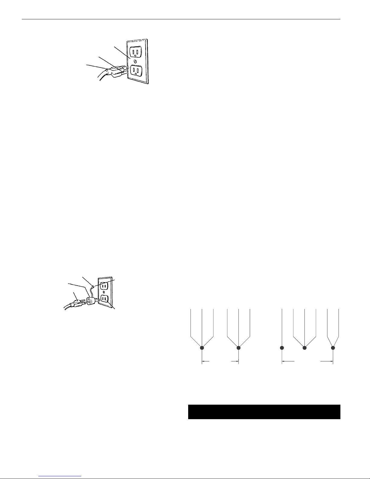
•Proper electrical outlet should be available for tool.
Three-prong plug should be plugged directly into properly
grounded, three-prong receptacle.
•Extension cords should have a grounding prong, and the three
wires of the extension cord should be of the correct gauge.
•Keep visitors at a safe distance from work area.
•Keep children out of workplace. Make workshop childproof. Use
padlocks, master switches or remove switch keys to prevent
any unintentional use of power tools.
TOOL SHOULD BE MAINTAINED
•Always unplug tool prior to inspection.
•Read operating instructions manual for specific maintaining
and adjusting procedures.
•Keep tool lubricated.
•Use sharp cutters and keep the tool clean for safest operation.
•Remove adjusting tools. Form the habit of checking that adjust-
ing tools are removed before turning on the machine.
•Keep all parts in working order. Check to determine that the
guard or other parts will operate properly and perform their
intended function.
•Check for damaged parts. Check for alignment of moving parts,
binding, breakage, mounting and any other condition that may
affect a tool’s operation.
•Damaged parts should be properly repaired or replaced. Do not
perform makeshift repairs. (Use the parts list provided to order
replacement parts.)
2
Palmgren Operating Manual & Parts List 80206

3
SAFETY RULES (CONTINUED)
KNOW HOW TO USE TOOL
•Use the right tool for the job. Do not force tool or attachment
to do a job for which it was not designed.
•Disconnect tool when changing accessories such as bits, cut-
ters and the like.
•Avoid accidental start-up. Make sure switch is in OFF position
before plugging in.
•Do not force tool. It will work most efficiently at the rate for
which it was designed.
•Handle workpiece correctly. Secure work with clamps or vise.
Leave hands free to operate machine, Protect hands from
possible injury.
•Never leave a tool running unattended.Turn the power off and
do not leave tool until it comes to a complete stop.
•Do not overreach. Keep proper footing and balance.
•Never stand on tool. Serious injury could occur if tool is tipped
or if cutter is unintentionally contacted.
•Keep hands away from moving parts and cutting surfaces.
•Know your tool. Learn its operation, application and specific
limitations.
•Feed work into a bit or cutter against the direction of rotation
of bit or cutter.
•Turn the machine off if it jams. A cutter jams when it digs too
deeply into the workpiece. (The motor force keeps it stuck in
workpiece.)
•Use recommended accessories. Refer to page 9. Use of improp-
er accessories may cause risk of injury to persons.
•Clamp workpiece or brace against column to prevent rotation.
•Use recommended speed for drill accessory and workpiece
material.
WARNING: Think Safety! Safety is a combination of operator com-
mon sense and alertness at all times when drill press is being used.
AASSSSEEMMBBLLYY
MOUNT COLUMN ASSEMBLY TO BASE
Refer to Figure 5.
•Place base (Ref. No. 1) on flat level surface.
•Mount column assembly (Ref. No. 2) to base using four socket
head bolts (Ref. No. 3).
MOUNT TABLE
Refer to Figure 5.
•Attach crank handle (Ref. No. 7) to shaft of worm gear (Ref. No.
11), rotate worm gear to remove slack, and shoulder crank han-
dle with set screw (Ref. No. 6).
•Attach table (Ref. No. 16) to table bracket (Ref. No. 12) using hex
head bolt and lock washer (Ref. Nos. 23 and 24).
•Thread hose fitting (Ref. No. 17) into table. Slide hose (Ref. No.
18) over hose fitting.
MOUNT HEAD ASSEMBLY
Refer to Figure 6.
WARNING: Although compact, the drill press head assembly is
heavy. Two people are required to mount the drill press head
assembly onto the column.
•Slide drill press head assembly onto top of column.
•Position head so that it is centered over base.
•Secure head by inserting threaded bushing (Ref. No. 64) into
left side of head, bushing (Ref. No. 66) into right side of head,
then insert and tighten socket head bolt (Ref. No. 67).
MOUNT MOTOR ADJUSTING HANDLE
Refer to Figure 6.
•Thread handle (Ref. No. 76) into motor mount plate (Ref. No. 77).
MOUNT QUILL FEED HANDLE ASSEMBLY
Refer to Figure 6.
•Place key (Ref. No. 5) into keyway of pinion (Ref. No. 6).
•Place quill feed handle assembly over pinion.
•Secure handle assembly with socket head bolt (Ref. No. 3) and
spacer (Ref. No. 4).
MOUNT DRILL CHUCK AND ARBOR
Refer to Figure 6.
•Be sure spindle taper, arbor taper and chuck taper are clean
and dry.
•Insert arbor into spindle, push arbor into spindle and twist
arbor slightly to release air trapped in taper. Make sure tang of
arbor seats properly into spindle.
•Mount chuck onto arbor, push chuck over arbor and twist
chuck slightly to release air trapped in taper.
•Place a block of wood on table, below chuck, and firmly pull
quill feed handle to securely seat chuck and arbor into spindle.
IINNSSTTAALLLLAATTIIOONN
Refer to Figures 1, 2 and 3.
MOUNT DRILL PRESS
•Drill press must be mounted to flat level surface. Use shims or
machine mounts if necessary. Do not mount drill press in direct
sunlight.
•Be sure to bolt drill press to floor or bench securely to prevent
tipping and minimize vibration.
•Tighten all nuts and bolts that may have loosened during
shipment.
POWER SOURCE
The motor is designed for operation on the voltage an frequency
specified. Normal loads will be handled safely on voltages not
more than 10% above or below the specified voltage.
Running the unit on voltages which are not within the range may
cause overheating and motor burn out. Heavy loads require that
the voltage at motor terminals be no less than the voltage speci-
fied.
GROUNDING INSTRUCTIONS
WARNING: Improper connection of equipment grounding con-
ductor can result in the risk of electrical shock. Equipment should
be grounded while in use to protect operator from electrical shock.
Check with a qualified electrician if grounding instructions are not
understood or if in doubt as to whether the tool is properly
grounded.
This tool is equipped with an approved 3-conductor cord rated up
to 300V and a 3-prong grounding type plug rated at 115V (See
Figure 1) for your protection against shock hazards.
Palmgren Operating Manual & Parts List 80206

4
INSTALLATION (CONTINUED)
Grounding plug should be plugged directly into a properly
installed and grounded 3-prong grounding-type receptacle, as
shown (Figure 1).
Do not remove or alter grounding prong in any manner. In the
event of a malfunction or breakdown, grounding provides a path
of least resistance for electrical shock.
WARNING: Do not permit fingers to touch the terminals of plug
when installing or removing from outlet.
Plug must be plugged into matching outlet that is properly
installed and grounded in accordance with all local codes and
ordinances. Do not modify plug provided. If it will not fit in outlet,
have proper outlet installed by a qualified electrician.
Inspect tool cords periodically, and if damaged, have repaired by
an authorized service facility.
Green (or green and yellow) conductor in cord is the grounding
wire. If repair or replacement of the electric cord or plug is neces-
sary, do not connect the green (or green and yellow) wire to a live
terminal.
Where a 2-prong wall receptacle is encountered, it must be
replaced with a properly grounded 3-prong receptacle installed in
accordance with National Electric Code and local codes and ordi-
nances.
WARNING: This work should be performed by a qualified electrician.
A temporary 3-prong to 2-prong grounding adapter (See Figure 2)
is available for connecting plugs to a two pole outlet if it is
properly grounded.
Do not use a 3-prong to 2-prong grounding adapter unless permit-
ted by local and national codes and ordinances.
(A 3-prong to 2-prong grounding adapter is not permitted in
Canada.) Where permitted, the rigid green tab or terminal on the
side of the adapter must be securely connected to a permanent
electrical ground such as a properly grounded water pipe, a prop-
erly grounded outlet box or a properly grounded wire system.
Many cover plate screws, water pipes and outlet boxes are not
properly grounded.To ensure proper ground, grounding means
must be tested by a qualified electrician.
EXTENSION CORDS
•The use of any extension cord will cause some drop in voltage
and loss of power.
•Wires of the extension cord must be of sufficient size to carry
the current and maintain adequate voltage.
•Use the table to determine the minimum wire size (A.W.G.)
extension cord.
•Use only 3-wire extension cords having 3-prong grounding
type plugs and 3-pole receptacles which accept the tool plug.
•If the extension cord is worn, cut, or damaged in any way,
replace it immediately.
EXTENSION CORD LENGTH
Wire Size . . . . . . . . . . . . . . . . . . . . . . . . . . . . . . . . . . . . . . . . . . . . . . . . . . .A.W.G.
Up to 25 ft. . . . . . . . . . . . . . . . . . . . . . . . . . . . . . . . . . . . . . . . . . . . . . . . . . . . . .14
25-50 ft. . . . . . . . . . . . . . . . . . . . . . . . . . . . . . . . . . . . . . . . . . . . . . . . . . . . . . . .12
NOTE: Using extension cords over 50 ft. long is not recommended.
POWER SOURCE
Drill press requires a 115/230 volt, 60 Hz power source.
To use the drill press with a 230V power supply, have a qualified
electrician attach a 230 volt, 20/30A three-prong plug onto drill
press line cord.
ELECTRICAL CONNECTIONS
Refer to Figure 3.
WARNING: All electrical connections must be performed by a
qualified electrician. Make sure unit is off and disconnected from
power source while motor is mounted, connected, reconnected or
anytime wiring is inspected.
•The motor should be wired for 115 volts an clockwise rotation
as viewed from shaft end of motor.
•A label on the motor describes the possible wiring configura-
tions.There are many different possible combinations, so only
the diagram provided with the motor should be used.
•Be sure to install motor cord so that the cover plate for the motor
wiring holds the cord in the groove of the motor end shield.The
motor cord must be secured to protect the wiring connections
from possible strain.
•The power supply to motor is controlled by a locking rocker
switch. Power lines are connected to the quick connect termi-
nals of the switch.
•The green ground line must remain securely fastened to the
motor ground terminal to provide proper grounding.
•To operate drill press at 230 volts, rewire motor as shown in
Figure 3 and replace line cord plug with a 230 volt, 15A, 3-prong
plug. If motor label has a different wiring configuration, use the
motor label diagram to rewire motor.
OOPPEERRAATTIIOONN
Refer to Figures 4, 5 and 6.
WARNING: Read and understand operating instructions and
parts manual before operating this machine.
Palmgren Operating Manual & Parts List 80206
Figure 2 – 2-Prong Receptacle with adapter
Grounding Lug
Adapter
3-Prong Plug
2-Prong Receptacle
Make sure this is
Connected to a known
Grounded Receptacle
Figure 1 – 3-Prong Receptacle
Properly Grounded Outlet
Grounding Prong
3-Prong Plug
Figure 3 – Wiring Schematic for Motor
To Change Rotation, Exchange Leads 5 and 6
U, V-Power Supply
115 Volts
1352
46
230 Volts
1
UVU V
235
46

5
Palmgren Operating Manual & Parts List 80206
OPERATION (CONTINUED)
CAUTION: The operation of any power tool can result in foreign
objects being thrown into the eyes, which can result in severe eye
damage. Always wear safety glasses complying with United States
ANSI Z87.1 (shown on package) before commencing power tool
operation.
SPEED ADJUSTMENTS
Refer to Figures 4 and 6.
WARNING: Be sure drill press is turned off and is disconnected
from power source before adjusting speeds.
•To change spindle speed, loosen motor lock handle (Ref. No.
75), pivot the motor toward front of drill press.This will loosen
the belt and permit relocating the belt to the desired pulley
groove for the required spindle speed (See Figure 4).
•After belt has been repositioned, pull handle (Ref. No. 76) to
move motor toward rear of drill press and tighten motor lock
handle.
•Check belt for proper tension and make any final adjustment. A
belt is properly tensioned when light pressure applied to mid-
point of the belt produces about 1/2” deflection.
TABLE ADJUSTMENTS
Refer to Figure 5.
•Height adjustments: To adjust table, loosen locking handle (Ref.
No. 15) and turn crank handle (Ref. No. 5) to desired height.
Immediately retighten table bracket locking handle.
•Rotation of work table : Loosen table locking handle (Ref. No.
15) and rotate table (Ref. No. 16) to desired position and
retighten handle.
•Tilting work table: Loosen hex head bolt (Ref. No. 23). Remove
pin and nut (Ref. No. 22). To do this, tighten nut until pin slips
out easily. Tilt table to desired angle up to 45° and retighten
hex head bolt. Reinsert pin and nut when returning the table to
0° position.
•To obtain more distance between chuck and table, the work
table can be rotated 180° and base can be used as a work sur-
face.This permits drilling of larger objects.
•Clamp table securely after adjustments have been made.
DEPTH STOP ADJUSTMENT
Refer to Figure 6.
To control drilling depth, use scale (Ref. No. 26) to adjust to desired
depth. Depress and hold pin, slide depth stop nut along lead screw
(Ref. Nos. 25, 27 and 29) until bottom edge of nut coincides with
the desired depth on the scale, then release pin. Use this feature to
drill more than one hole to the same depth.
MOUNT DRILL BIT
WARNING: Be sure drill press is turned off and is disconnected
from power source before adjusting speeds.
•Place drill bit in jaws of drill chuck.
•Tighten chuck with drill chuck key. Be sure to tighten the chuck
using all three key positions on the chuck body and remove
chuck key.
Spindle
Rotation
Spindle Motor
Figure 4 – Spindle Speed Adjustment
D
C
B
A
Z
Y
X
W
4
3
2
1
D4-1W
C3-1W
D4-2X
B2-1W
C3-2X
D4-3Y
A1-2X
B2-3Y
C3-4Z
A1-3Y
B2-4Z
A1-4Z
2450
1850
1480
1300
1110
890
530
470
400
320
280
190
in/mm
3/8 9.5
5/8 15.9
7/8 22.2
7/8 22.2
7/8 22.2
1 25.4
11⁄431.8
11⁄431.8
15⁄841.3
15⁄841.3
2 50.8
2 50.8
in/mm
1/4 6.4
3/8 9.5
1/2 12.7
1/2 12.7
1/2 12.7
5/8 15.9
3/4 19.0
3/4 19.0
7/8 22.2
7/8 22.2
1 25.4
1 25.4
in/mm
7/32 5.6
11/32 8.7
15/32 11.9
15/32 11.9
15/32 11.9
9/16 14.3
11/16 17.5
11/16 17.5
3/4 19.0
3/4 19.0
7/8 22.2
7/8 22.2
in/mm
3/16 4.8
5/16 7.9
7/16 11.1
7/16 11.1
7/16 11.1
1/2 12.7
5/8 15.9
5/8 15.9
13/16 20.6
13/16 20.6
1 25.4
1 25.4
in/mm
1/8 3.2
1/4 6.4
11/32 8.7
11/32 8.7
11/32 8.7
7/16 11.1
1/2 12.7
1/2 12.7
5/8 15.9
5/8 15.9
3/4 19.0
3/4 19.0
in/mm
3/32 2.4
5/32 4.0
1/4 6.4
1/4 6.4
1/4 6.4
5/16 7.9
3/8 9.5
3/8 9.5
1/2 12.7
1/2 12.7
5/8 15.9
5/8 15.9
in/mm
1/16 1.6
1/8 3.2
3/16 4.8
3/16 4.8
3/16 4.8
1/4 6.4
5/16 7.9
5/16 7.9
7/16 11.1
7/16 11.1
9/16 14.3
9/16 14.3
in/mm
3/64 1.2
1/16 1.6
1/8 3.2
1/8 3.2
1/8 3.2
3/16 4.8
1/4 6.4
1/4 6.4
3/8 9.5
3/8 9.5
1/2 12.7
1/2 12.7
Belt
Location RPM Wood
Zinc
Diecast
Alum. &
Brass Plastic
Cast Iron
& Bronze
Steel
Mild &
Malleable
Steel Cast &
Med.
Carbon
Steel
Stainless &
Tool

6
Palmgren Operating Manual & Parts List 80206
MMAAIINNTTEENNAANNCCEE
WARNING: Turn switch off and remove plug from power source
outlet before maintaining or lubricating your drill press
V-BELT
Replace V-belt when worn.
LUBRICATION
Refer to Figures 5 and 6.
The ball bearings are lubricated at the factory and need no further
lubrication. Using 20wt. non detergent oil, periodically lubricate
the splines (grooves) in the spindle and the rack (teeth on the
quill) as follows:
•Lower quill assembly (Figure 6, Ref. No. 20) all the way down.
•Apply lubricant around the inside of the hole in the spindle
pulley (Figure 6, Ref. No. 50).
•Apply lubricant to rack (teeth) on quill (Figure 6, Ref. No. 14)
while extended below drill press head.
•Apply lubricant to rack and pinion gear (Figure 5, Ref. Nos. 4
and 9) on column and table assembly.
CLEAN MOTOR
Frequently blow out any dust that may accumulate inside motor. If
power cord is worn, cut or damaged in any way, have it replaced
immediately.

7
SYMPTOM
Spindle does not turn
Noisy spindle
Noisy operation
Bit burns or smokes
Excessive drill runout or wobble
Drill bit binds in workpiece
POSSIBLE CAUSES
1. No power to drill press
2. Defective switch
3. Defective motor
Defective bearings
1. Incorrect bet tension
2. Dry spindle
3. Loose spindle
4. Loose motor pulley
1. Incorrect speed
2. Chips not coming out of table
3. Dull bit
4. Feeding too slow
5. Bit not lubricated
6. Bit running backwards
1. Bent bit
2. Bit not properly installed in chuck
3. Chuck not properly installed
4. Worn spindle bearings
1. Workpiece pinching bit or excessive feed
2. Improper belt tension
3. Workpiece not supported or clamped
properly
CORRECTIVE ACTION
1. Check wiring, fuse or circuit breaker
2. Replace switch
3. Replace motor
Replace bearings
1. Adjust tension
2. Lubricate spindle, See Lubrication, page 6
3. Tighten pulley nut
4. Tighten set screw in pulley
1. Change speed
2. Retract bit frequently to clear chips
3. Sharpen or replace bit
4. Feed faster; enough to allow drill to cut
5. Lubricate bit
6. Check motor rotation to be sure it is
clockwise facing shaft end
1. Replace bit
2. Install bit properly
3. Install chuck properly
4. Replace bearings
1. Support or clamp work, decrease feed
pressure
2. Adjust tension
3. Support or clamp workpiece securely
TTRROOUUBBLLEESSHHOOOOTTIINNGG
Palmgren Operating Manual & Parts List 80206

11
6
19
19
10
8
12
18
6
5
4
15
16
17
7
23
21
20
22
25
24
13
14
2
3
9
1
8
Figure 5 - Replacement Parts Illustration for Base
Palmgren Operating Manual & Parts List 80206

9
Palmgren Operating Manual & Parts List 80206
RREEPPLLAACCEEMMEENNTTPPAARRTTSSLLIISSTTFFOORRBBAASSEE
∆Not Shown.
* Standard hardware item available locally.
Ref. Part Number for:
No. Description 80206 Qty.
1 Base 18806.09 1
2 Column Assembly 18807.09 1
3 10-1.50 x 40mm Socket Head Bolt * 4
4 Rack 18808.00 1
5 Handle 17231.00 1
6 8-1.25 x 8mm Set Screw * 2
7 Crank 17232.00 1
8 Threaded Bushing 18809.00 1
9 Pinion Gear and Shaft 17234.00 1
10 Worm and Pinion Gear Set (Ref. Nos. 9 and 11) 17235.00 1
11 Worm Gear 17236.00 1
12 Table Bracket 18810.09 1
13 Rack Retaining Ring 18811.00 1
14 Bushing 18812.00 1
15 Table Bracket Locking Handle 17239.00 1
16 Table 18814.09 1
17 Hose Fitting 17241.00 1
18 Hose 17242.00 1
19 Rivet 01286.00 4
20 Indicator 17244.00 1
21 Scale 17245.00 1
22 Pin and Nut 17246.00 1
23 20-2.5 x 60mm Hex Head Bolt * 1
24 20mm Lock Washer * 1
25 10mm Lock Washer * 4
Recommended Accessories
∆4” Angle Vise 11351 1
∆4” Drill Press Vise 12352 1
∆4” Standard Vise 12403 1
∆6”Quick Grip Vise 12621 1
∆6” Standard Vise 12601 1
∆6” Cross Vise 30601 1

10
Palmgren Operating Manual & Parts List 80206
Figure 6 - Replacement Parts Illustration for Head
35
62
66
67
68
81
65
23
53
74
14
73
13
13
29
59
36
20
30
80 79
4
51
52
61
71
72
39
7
50
6
9
8
28
43
48
13
5
3
3
3
2
1
22
33
34
75
60
26
11
37
46
46 44
54
49
38
42
42
69
12
27
32
25
21
31
41
56
47
19
19 77
78
18
17
15
16
24
57
63
40
76
55
10
64
45
70
58

Ref.
No. Description Part No. Qty.
1 Quill Handle 17247.09 1
2 Grip 17248.01 3
3 6-1.0 x 10mm Socket Head Bolt * 6
4 Spacer 17249.00 1
5 7 x 8 x 24mm Key 18757.00 1
6 Pinion 18813.00 1
7 10-1.5mm Hex Nut * 1
8 10-1.5 x 40mm Dog Point Set Screw 02576.00 1
9 JT3 Chuck with Key 15351.00 1
10 Chuck Key 15352.00 1
11 MT3/JT3 Arbor 18838.00 1
12 Spindle 18818.00 1
13 6206ZZ Ball Bearing 20006.00 3
14 Quill 18819.00 1
15 Rubber Bumper 18820.00 1
16 6204ZZ Ball Bearing 00989.00 1
17 Keyed Washer 18821.00 1
18 Spindle Lock Nut 18822.00 1
19 51106 Thrust Bearing 18129.00 2
20 Lower Spindle and Quill Assembly 18823.00 1
(Ref. Nos. 12 through 19)
21 Drift Key 18839.00 1
22 6-1.0 x 20mm Socket Head Bolt * 1
23 12-1.75mm Hex Nut * 1
24 Depth Stop Collar 18824.09 1
25 Depth Stop Lead Screw 20003.00 1
26 Scale 18826.00 1
27 Pin 17260.00 1
28 Spring 17261.00 1
29 Depth Stop Nut 17262.00 1
30 Switch 16080.00 1
31 4-0.7 x 10mm Pan Head Screw * 5
32 Switch Plate 17263.00 1
33 4mm Flat Washer * 2
34 Bracket 20004.00 1
35 6-1.0 x 12mm Socket Head Bolt * 2
36 Flange 17265.00 1
37 2.5 x 14mm Spring Pin 03378.00 1
38 4-0.7 x 12mm Flat Head Screw * 3
39 Cap Cover with Spring 18827.00 1
40 12-1.25mm Hex Nut * 2
41 Grommet 04076.00 2
42 6mm Flat Washer * 5
Ref.
No. Description Part No. Qty.
43 Cord Clamp 04078.01 1
44 6-1.0mm Hex Nut * 1
45 3AMI-30 Retaining Ring 01465.00 1
46 62mm Retaining Ring 00489.00 2
47 Spacer 18828.00 1
48 Spindle Sleeve 18829.00 1
49 Upper Spindle Assembly 18830.00 1
(Ref. Nos. 13, 19, 45-48)
50 Spindle Pulley 18831.00 1
51 V-belt 06368.00 1
52 Spindle Sleeve Nut 18832.00 1
53 6202ZZ Ball Bearing 01540.00 1
54 Transmitting Pulley 18835.00 1
55 V-belt 18840.00 1
56 Pulley Shaft 18834.00 1
57 Knob 18762.00 1
58 6-1.0 x 10mm Pan Head Screw * 1
59 Motor Pulley 18836.00 1
60 3/16 x 13/8mm Key 01409.00 1
61 8-1.25 x 8mm Set Screw * 1
62 Pulley Housing 18833.00 1
63 Strain Relief 17277.00 2
64 Threaded Bushing 17278.00 1
65 6 x 20mm Spring Pin 01596.00 2
66 Bushing 17280.00 1
67 10-1.5 x 90mm Socket Head Bolt 17281.00 1
68 Head 18837.09 1
69 Line Cord 17282.00 1
70 Motor 20212.00 1
71 Switch Cord 17284.00 1
72 12-1.75 x 25mm Socket Head Bolt * 1
73 12mm Lock Washer * 1
74 12mm Flat Washer * 1
75 Motor Locking Handle 17285.00 1
76 Handle 17286.00 1
77 Motor Mount Plate 17287.00 1
78 3/8-16 x 3/4” Flat Head Screw * 4
79 Plate 17272.00 1
80 10-1.5 x 20mm Flat Head Screw * 4
81 4mm Serrated Washer * 2
∆Hardware Bag 20211.00 1
∆Operator’s Manual 20155.09 1
11
Palmgren Operating Manual & Parts List 80206
RREEPPLLAACCEEMMEENNTTPPAARRTTSSLLIISSTTFFOORRHHEEAADD
∆Not Shown.
* Standard hardware item available locally.

WWAARRRRAANNTTYY
FULL TWO YEAR WARRANTY ON PALMGREN DRILL PRESS
If within two full years from the date of purchase, this Palmgren Drill Press fails due to a defect in material or
workmanship, Palmgren will repair it free of charge.
To order parts for a non-warranty repair, please contact your preferred Palmgren distributor.To obtain the names of Palmgren
distributors or to arrange warranty return, please call Palmgren Steel Products directly at (800) 621-6145.
This warranty gives you specific legal rights and you may have other rights which vary from state to state.
Palmgren Steel Products, Inc., 914 N. Kilbourn Avenue, Chicago, IL 60651-3426
Palmgren Operating Manual & Parts List 80206
Table of contents
Other Palmgren Power Tools manuals

Palmgren
Palmgren 9661614 Instructions for use

Palmgren
Palmgren 80207 User manual

Palmgren
Palmgren 84261A User manual

Palmgren
Palmgren MTC18 User manual

Palmgren
Palmgren 80177 User manual

Palmgren
Palmgren 9661610 Instructions for use

Palmgren
Palmgren 9661104 User manual

Palmgren
Palmgren 9680130 User manual

Palmgren
Palmgren 0.5-Ton Arbor Press User manual

Palmgren
Palmgren 80341A User manual

Palmgren
Palmgren 80174 User manual

Palmgren
Palmgren 80110B User manual

Palmgren
Palmgren 80110A User manual

Palmgren
Palmgren 80171 User manual

Palmgren
Palmgren 61101C User manual

Palmgren
Palmgren 61051C User manual

Palmgren
Palmgren 80150 User manual

Palmgren
Palmgren 32806 User manual

Palmgren
Palmgren 80329 User manual