Palmgren 9680130 User manual

operat ng manual & parts l st
9680130
16'' Drill press W/PF
Read carefully and follow all safety rules and operating instructions before
first use of this product.

1Safety
1.1 Rating plate ............................................................................................................................................ 4
1.2 Safety instructions (warning notes) ........................................................................................................ 5
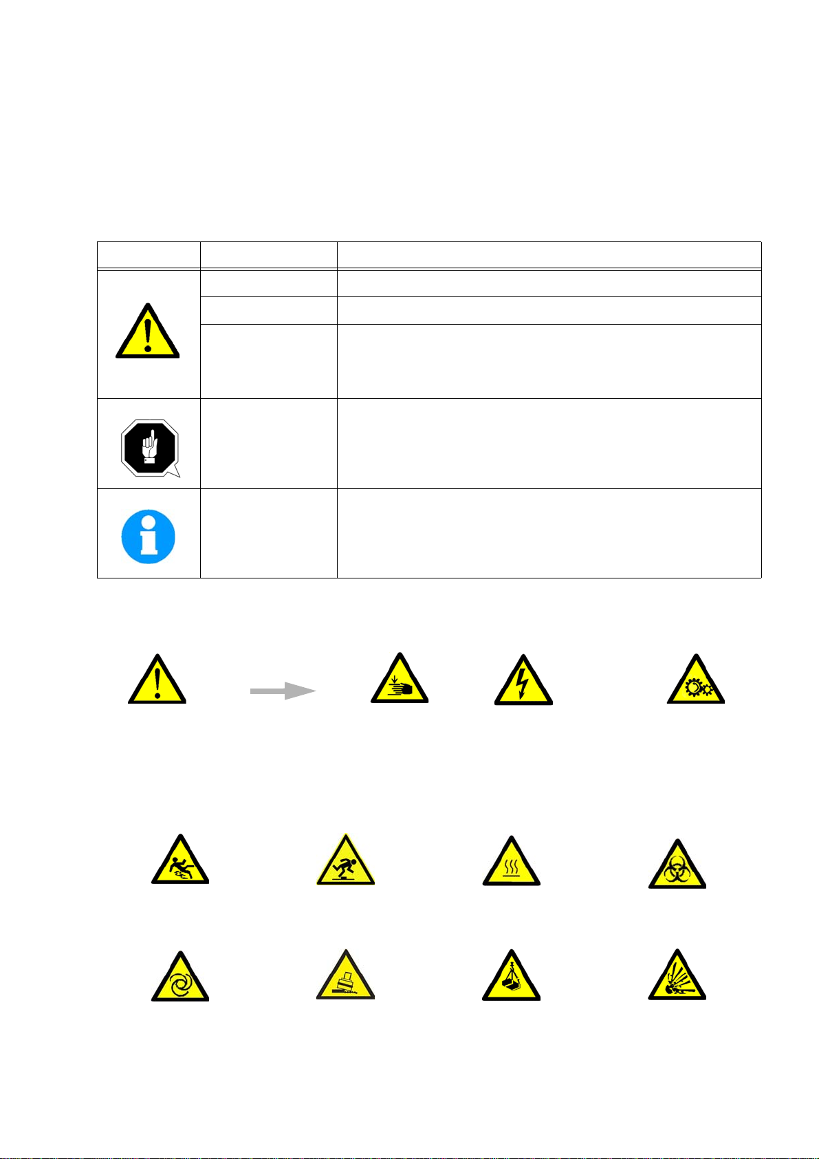
1.2.1 Classification of hazards ............................................................................................................. 5
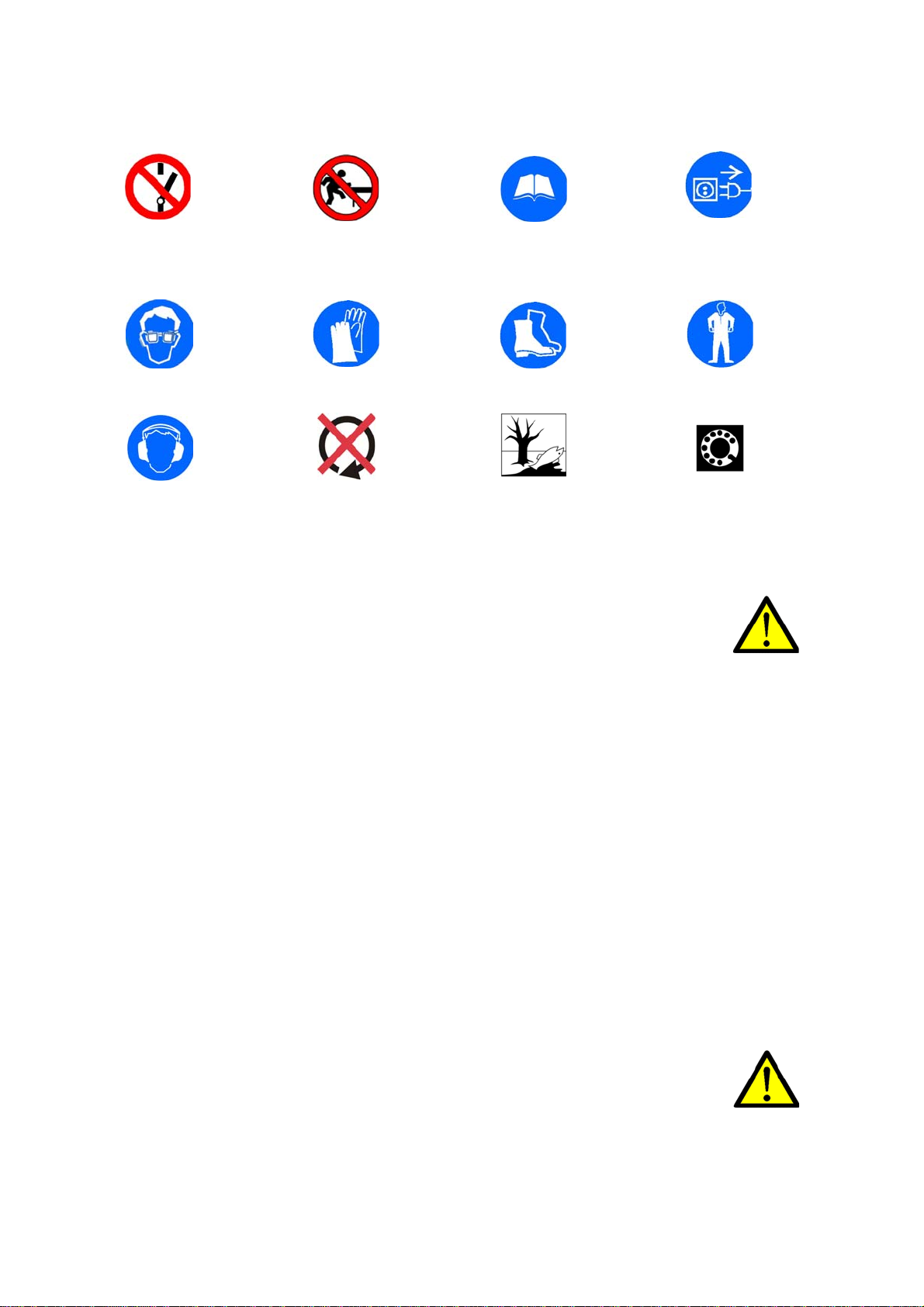
1.2.2 Other pictograms......................................................................................................................... 5
1.3 Intended use........................................................................................................................................... 6
1.4 Reasonably foreseeable misuse ............................................................................................................ 7
1.4.1 Avoiding misuse.......................................................................................................................... 7
1.5 Possible dangers caused by the drilling machine .................................................................................. 7
1.6 Qualification............................................................................................................................................ 8
1.6.1 Target group private users.......................................................................................................... 8
1.6.2 Obligations of the User................................................................................................................ 8
1.6.3 Additional requirements regarding the qualification .................................................................... 8
1.7 User positions......................................................................................................................................... 9
1.8 Safety measures during operation ......................................................................................................... 9
1.9 Safety devices ........................................................................................................................................ 9
1.10 Safety check..........................................................................................................................................10
1.11 Emergency-stop switch .........................................................................................................................10
1.11.1 Master switch .............................................................................................................................10
1.11.2 Drill chuck guard ........................................................................................................................ 11
1.12 Personal protective equipment...............................................................................................................11
1.13 Safety during operation .........................................................................................................................12
1.14 Safety during maintenance.....................................................................................................................12
1.14.1 Disconnecting and securing the drilling machine........................................................................12
1.15 Using lifting equipment ...........................................................................................................................12
1.15.1 Mechanical maintenance ...........................................................................................................12
1.16 Accident report ......................................................................................................................................13
1.17 Electronics.............................................................................................................................................13
1.18 Inspection deadlines.............................................................................................................................. 13
2 Technical specification
2.1 Emissions ..............................................................................................................................................14
2.2Dimensions DH28FS(9680130 ) ............................................................................................................16
3 Assembly
3.1 Scope of delivery ...................................................................................................................................18
3.2 Transport ...............................................................................................................................................18
3.3 Set-up and assembly.............................................................................................................................18
3.3.1 Installation siterequirements......................................................................................................19
3.4 Installation..............................................................................................................................................19
3.4.1 Fixing..........................................................................................................................................19
3.5 First commissioning...............................................................................................................................20
3.5.1 Electrical connection ..................................................................................................................20
3.5.2 Warming up the machine ...........................................................................................................21
1

4Operation
4.1 Control and indicating elements ............................................................................................................ 22
4.1.1 Drilling machine DH28FT - DH28FS(9680130) ......................................................................... 22
4.1.2 Control panel ............................................................................................................................... 23
4.2 Safety......................................................................................................................................................23
4.3 Switching on the machine.......................................................................................................................24
4.4 Switching off the machine.......................................................................................................................24
4.5 Speed variation.......................................................................................................................................24
4.5.1 Speed table .................................................................................................................................24
4.6 Drill depth stop........................................................................................................................................25
4.7 Automatic spindle sleeve feed ................................................................................................................25
4.8 Disassembly, assembly of drill chucks and drill bits ............................................................................... 25
4.9 Cooling....................................................................................................................................................25
4.10 Before starting work................................................................................................................................26
4.11 During work.............................................................................................................................................26
5 Maintenance
5.1 Safety......................................................................................................................................................27
5.1.1 Preparation.................................................................................................................................. 27
5.1.2 Restarting ................................................................................................................................... 27
5.2 Inspection and maintenance................................................................................................................... 27
5.3 Repair .....................................................................................................................................................29
5.3.1 Customer service technician .......................................................................................................29
6 Malfunctions
7 Appendix
7.1 Copyright ................................................................................................................................................31
7.2 Terminology/Glossary.............................................................................................................................31
7.3 Liability claims/warranty..........................................................................................................................31
7.4 Advice for disposal / Options of reuse: ...................................................................................................32
7.4.1 Decommissioning ........................................................................................................................32
7.4.2 Disposal of new device packaging ..............................................................................................32
7.4.3 Disposal of the old device ...........................................................................................................32
7.4.4 Disposal of electrical and electronic components .......................................................................33
7.5 Disposal via municipal collection facilities ..............................................................................................33
7.6 Product follow-up....................................................................................................................................33
7.7 Storage ...................................................................................................................................................33
8 Ersatzteile - Spare parts
8.1 Bohrkopf - Drilling head ..........................................................................................................................35
8.2 Pinolenvorschub - Spindle sleeve feed...................................................................................................36
8.2.1 Keilriemenantrieb - V-belt drive ...................................................................................................37
2

8.2.2 Säule und Bohrtisch - Column and drilling table ......................................................................... 38
8.3 Ersatzteilliste - Parts list ......................................................................................................................... 39
8.4Bohrfutterschutz - Drill chuck protection................................................................................................. 43
8.5 Schaltplan - Wiring diagram DH28FT/DH28FS(9680130).................................................................. 44
3

1 Safety
Glossary of symbols
This part of the operating instructions
explains the meaning and use of the warning notes included in these operating instructions,
defines the intended use of the drilling machine,
points out the dangers that might arise for you or others if these instructions are not
observed,
informs you about how to avoid dangers.
In addition to these operation instructions, please observe
the applicable laws and regulations,
the statutory provisions for accident prevention,
the prohibition, warning and mandatory signs as well as the warning notes on the drilling
machine.
Always keep this documentation close to the drilling machine.
1.1 Rating plate
INFORMATION
If you are unable to rectify an issue using these operating instructions, please contact us for
advice:
Exclusive USA Agent
C.H.HANSON
2000 North Aurora Rd.
Naperville,IL 60563
provides further instructions
calls on you to act
listings
4

1.2 Safety instructions (warning notes)
1.2.1 Classification of hazards
We classify the safety warnings into different categories. The table below gives an overview of
the classification of symbols (ideogram) and the warning signs for each specific danger and its
(possible) consequences.
1.2.2 Other pictograms
Symbol Alarm expression Definition / consequence
DANGER! Impending danger that will cause serious injury or death to people.
WARNING! A danger that can cause serious injury or death.
CAUTION!
A danger or unsafe procedure that can cause personal injury or damage to
property.
ATTENTION!
Situation that could cause damage to the drilling machine and product, as
well as other types of damage.
No risk of injury to persons.
Information
Practical tips and other important or useful information and notes.
No dangerous or harmful consequences for people or objects.
In case of specific dangers, we replace the pictogram with
or
general danger with a warning of injury to hands, hazardous electri-
cal voltage,
rotating parts.
Warning: danger of slip-
ping!
Warning: risk of stumbling! Warning: hot surface! Warning: biological hazard!
Warning: automatic start-
up!
Warning: tilting danger! Warning: suspended loads! Caution, danger of explo-
sive substances!
5

1.3 Intended use
WARNING!
In the event of improper use of the drilling machine
will endanger personnel,
will endanger the machine and other material property of the operating company,
the correct function of the drilling machine may be affected.
The drilling machine is designed and manufactured to be used in a non-explosive environment.
The drilling machine is designed and manufactured for holes in cold metals or other non flam-
mable materials or that not constitute a health hazard using a rotating filing-stripping tool that
has a number of grooves for collecting the filings.
If the drilling machine is used in any way other than described above, modified without authori-
zation of Optimum Maschinen Germany GmbH, then the geared drill is being used improperly.
We will not be held liable for any damages resulting from any operation which is not in accord-
ance with the intended use.
We expressly point out that the guarantee will expire, if any constructive, technical or proce-
dural changes are not performed by the company Optimum Maschinen Germany GmbH.
It is also part of the intended use that you
observe the limits of the drilling machine,
observe the operating instructions,
and comply with the inspection and maintenance instructions.
"Technical specification“ on page 52
WARNING!
Extremely severe injuries.
It is forbidden to make any modifications or alternations to the operation values of the
drilling machine! They could endanger the personnel and cause damage to the drilling
machine.
Switching on forbidden! Do not climb onto the
machine!
Read the operating instruc-
tions before commission-
ing!
Pull out the mains plug!
Wear protective glasses! Wear protective gloves! Wear safety shoes! Wear a protective suit!
Use ear protection! Only switch during stand-
still!
Protect the environment! Contact address
6

1.4 Reasonably foreseeable misuse
Any use other than that specified under "Intended use" or any use beyond that described will be
deemed non-intended use and is not permissible.
Any other use has to be discussed with the manufacturer.
It is only allowed to process metal, cold and non-inflammable materials with the drilling
machine.
In order to avoid misuse, it is necessary to read and understand the operating instructions
before first commissioning.
Operators must be qualified.
1.4.1 Avoiding misuse
Use of suitable cutting tools.
Adapting the speed setting and feed to the material and workpiece.
Clamp workpieces firmly and free of vibration.
ATTENTION!
The workpiece is always to be fixed by a machine vice, jaw chuck or by another
appropriate clamping tool such as for the clamping claws.
WARNING!
Risk of injury caused by flying workpieces.
Clamp the workpiece in the machine vice. Make sure that the workpiece is firmly clamped in the
machine vice and that the machine vice is firmly clamped onto the machine table.
Use cooling and lubricating agents to increase the durability of the tool and to improve the
surface quality.
Clamp the cutting tools and workpieces on clean clamping surfaces.
Sufficiently lubricate the machine.
Set the bearing clearance and guides correctly.
Recommendations:
Insert the drill in a way that it is exactly positioned between the three clamping jaws of the
quick action chuck.
When drilling, make sure that
the suitable speed is set depending on the diameter of the drill,
the pressure must only be such that the drill can cut without load,
if there is too much pressure, the drill will wear quickly and may even break or jam in the
borehole. If the drill jams, immediately stop the main motor by pressing the emergency stop
switch,
use commercial cooling/lubricating agents for hard materials, e.g. steel and
generally always back the spindle out of the workpiece while it is still turning.
1.5 Possible dangers caused by the drilling machine
The drilling machine was built using state-of-the-art technology.
Nevertheless, there is a residual risk as the drilling machine operates with
at high speeds,
with rotating parts,
electrical voltage and currents.
We have used design and safety engineering to minimize the health risk to personnel resulting
from these hazards.
7

If the drilling machine is used and maintained by personnel who are not duly qualified, there
may be a risk resulting from incorrect or unsuitable maintenance of the geared drill.
INFORMATION
Everyone involved in the assembly, commissioning, operation and maintenance must
be duly qualified,
and strictly follow these operating instructions.
In the event of improper use
there may be a risk to personnel,
there may be a risk to the machine and other material values,
the correct function of the drilling machine may be affected.
Always disconnect the drilling machine if cleaning or maintenance work is being carried out, or
is no longer in use.
WARNING!
The drilling machine may only be operated with functional safety devices.
Disconnect the drilling machine immediately, whenever you detect a failure in the safety
devices or when they are not fitted!
All additional devices installed by the operator must be equipped with the stipulated
safety devices. This is your responsibility as the operator!
"Safety devices“ on page 47
1.6 Qualification
1.6.1 Target group private users
The machine can be used in the private domain. The acumen of people in the private sector
with training in metal working was taken into consideration for creating this operation manual.
Vocational training or further instruction in a metal working profession is a prerequisite for safe
operation of the machine. It is essential that the private user is aware of the dangers involved in
operating this machine. We recommend attending a training course in the use of drills. Your
specialist dealer can offer you an appropriate training course. These courses are also offered at
adult education centres in Germany.
1.6.2 Obligations of the User
The user must
have read and understood the operating manual,
be familiar with all safety devices and regulations,
be able to operate the drilling machine.
1.6.3 Additional requirements regarding the qualification
The following additional requirements apply for work on electrical components or equipment:
They must only be performed by a qualified electrician or person working under the instruc-
tions and supervision of a qualified electrician.
Before starting work on electrical parts or operating agents, the following actions must be taken
in the order given:
disconnect all poles,
secure against restarting,
check that there is no voltage.
8

1.7 User positions
The operator position is in front of the drilling machine.
1.8 Safety measures during operation
CAUTION!
Danger due to inhaling dust and mist that is hazardous to health.
Dependent on the material which need to be processed and the used auxiliaries dusts
and mist may be caused which might impair you health.
Ensure that the harmful dust and mist generated are safely sucked off at the point of
origin and routed away from the working area or filtered. To do so, use a suitable
extraction unit.
CAUTION!
Risk of fire and explosion by using flammable materials or cooling lubricants.
Before processing inflammable materials (e.g. aluminium, magnesium) or using
inflammable auxiliary materials (e.g. spirit) it is necessary to take additional preventive
measures in order to safely avoid health risks.
1.9 Safety devices
Use the drilling machine only with properly functioning safety devices.
Stop the drilling machine immediately, if a safety device fails or is faulty or becomes ineffective.
It is your responsibility!
If a safety device has been activated or has failed, the drilling machine must only be used if you
the cause of the fault has been eliminated,
you have verified that there is no danger to personnel or objects.
WARNING!
If you bypass, remove or deactivate a safety device in any other way, you are
endangering yourself and other personnel working with the drilling machine. The
possible consequences are
injuries due to components or workpieces flying off at high speed,
contact with rotating parts,
fatal electrocution,
The drilling machine features the following safety devices:
an emergency stop push button,
a drilling table with T-slots to fix the workpiece or a vice,
a drill chuck guard, in order to prevent interference with the rotating tool.
INFORMATION
The drilling machine can only be switched on if the drill chuck guard is closed.
WARNING!
Although the isolating safety devices provided and delivered with the machine are
designed to reduce the risks of workpieces being ejected or parts of tools or workpieces
breaking off, they cannot eliminate these risks completely. Always work carefully and
observe the limits of the machining process.
9

1.10 Safety check
Check the drilling machine before each start-up or at least once per shift. Inform the person
responsible immediately of any damage, defects or changes in the operating function.
Check all safety devices
at the beginning of each shift (with the machine stopped),
once a week (with the machine in operation) and
after all maintenance and repair work.
Check that prohibition, warning and information signs and the labels on the drilling machine
are legible (clean them, if necessary)
are complete (replace if necessary).
INFORMATION
Organise the checks according to the following table;
1.11 Emergency-stop switch
ATTENTION!
The drilling spindle keeps turning for a short time even after actuating the emergency
stop push button depending on the preset speed.
1.11.1 Master switch
WARNING!
Dangerous voltage even if the main switch is switched off.
The areas marked by the pictogram might contain live parts, even if the master switch is
switched off.
In the "0" position, the lockable main switch can be secured against accidental or non-author-
ised switching on by means of a padlock.
The power supply is cut off when the master switch is in the off position.
General check
Equipment Check OK
Guards Mounted, firmly bolted and not damaged
Signs,
Markers
Installed and legible
Date: Checked by (signature):
Functional check
Equipment Check OK
Emergency-stop switch The drilling machine must switch off after the emergency stop
impact switch has been actuated.
Drill chuck guard The drilling machine may only switch on, if the drill chuck
guard is closed. The engine must switch off when the drill
chuck guard is opened during operation.
Date: Checked by (signature):
10

Img.1-1: Master switch
1.11.2 Drill chuck guard
Adjust the guard to the correct height before you start working.
To do so, slacken the clamping screw, set the required height and re-tighten the clamping
screw.
There is a switch integrated in the spindle protection mounting which monitors the closed posi-
tion.
INFORMATION
The machine cannot be started, if the drill chuck guard is not closed.
1.12 Personal protective equipment
For some works you need personnel protective equipment as protective equipment. These are
Safety helmet,
protective glasses or face guard,
protective gloves,
safety shoes with steel toe caps,
ear protection.
Before starting work make sure that the required personnel protective equipment is available at
the work place.
CAUTION!
Soiled personal protection equipment that may be contaminated may cause illness.
Clean your personal protective equipment
after each use,
regularly once a week.
Personal protective equipment for special works
Protect your face and your eyes: Wear a safety helmet with facial protection when performing
work where your face and eyes are exposed to hazards.
Wear protective gloves when handling pieces with sharp edges.
Wear safety shoes when you assemble, disassemble or transport heavy components.
Master switch
Emergency-stop
11

1.13 Safety during operation
We provide information about the specific dangers when working with and on the drilling
machine in the descriptions for these types of work.
WARNING!
Before switching on the drilling machine make sure that there are
no dangers generated for persons,
no objects are damaged.
Avoid any unsafe work methods:
Make sure that your operation does not create asafety hazard.
The rules specified in these operating instructions must be observed during assembly,
operation, maintenance and repair.
Do not work on the drilling machine if your concentration is reduced, for example, because
you are taking medication.
Observe the accident prevention regulations issued by your Employers Liability Insurance
Association or other supervisory authorities applicable to your company.
Inform the supervisor about all hazards or faults.
Stay on the drilling machine until the machine completely stopped moving.
Use the specified personal protective equipment. Ensure you wear close-fitting clothing
and, if necessary, ahairnet.
Do not use protective gloves when drilling.
1.14 Safety during maintenance
Inform the operators in good time of any maintenance and repair works.
Report all safety relevant changes and performance details of the drilling machine or their oper-
ational behavior. Any changes must be documented, the operating instructions updated and
machine operators instructed accordingly.
1.14.1 Disconnecting and securing the drilling machine
Switch off the drilling machine with the main switch and secure the main switch with a padlock
against unauthorised switching-on or switching-on by accident.
All machine parts as well as all dangerous voltages are switched off. Excepted are only the
positions which are marked with the adjoining pictogram.
1.15 Using lifting equipment
WARNING!
The use of unstable lifting and load suspension equipment that might break under load
can cause severe injuries or even death.
Check that the lifting and loadsuspension gear
they have sufficient load carrying,
and that it is in perfect condition.
Observe the accident prevention regulations issued by your Employers Liability
Insurance Association or other supervisory authorities applicable to your company.
Fasten the loads carefully. Never walk under suspended loads!
1.15.1 Mechanical maintenance
Reinstall all protection and safety devices after any maintenance workonce the work has been
completed.This includes:
covers,
safety instructions and warning signs,
12

grounding cables.
Check if they are working properly!
1.16 Accident report
Inform your supervisors and Optimum Maschinen Germany GmbH immediately in the event of
accidents, possible sources of danger and any actions which almost led to an accident (near
misses).
There are many possible causes for "near misses".
The sooner they are notified, the quicker the causes can be eliminated.
1.17 Electronics
INFORMATION
Have the machine and/or the electric equipment checked regularly. Immediately eliminate all
defects such as loose connections, defective wires, etc.
For craft and industry
Have the machine and/or the electric equipment checked regularly. Immediately eliminate all
defects such as loose connections, defective wires, etc.
A second person must be present during work on live components to disconnect the power in
the event of an emergency. Disconnect the machine immediately if there is a malfunction in the
power supply!
Comply with the required inspection intervals in accordance with the factory safety directive,
operating equipment inspection.
The operator of the machine must ensure that the electrical systems and operating equipment
are inspected with regards to their proper condition, namely,
by a qualified electrician or under the supervision and direction of a qualified electrician,
prior to initial commissioning and after modifications or repairs, prior to recommissioning
and at set intervals.
The deadlines must be set so that arising, foreseeable defects can be detected in a timely man-
ner.
The relevant electro-technical rules must be followed during the inspection.
The inspection prior to initial commissioning is not required if the operator receives confirma-
tion from the manufacturer or installer that the electrical systems and operating equipment com-
ply with the accident prevention regulations, see conformity declaration.
Permanently installed electrical systems and operating equipment are considered constantly
monitored if they are continually serviced by qualified electricians and inspected by means of
measurements in the scope of operation (e.g. monitoring the insulation resistance).
1.18 Inspection deadlines
For craft and industry
Define and document the inspection deadlines for the machine in accordance with § 3 of the
Factory Safety Act and perform an operational risk analysis in accordance with § 6 of the Work
Safety Act. Also use the inspection intervals in the maintenance section as reference values.
13

2 Technical specification
The following information represents the dimensions and indications of weight and the manu-
facturer‘s approved machine data.
2.1 Emissions
Maximum sound pressure level at 1 m distance from the machine and 1.60 m above the ground
is 76 dB(A) to 79 dB(A) when idling.
If the drilling is installed in an area where various machines are in operation, the noise expo-
sure (immission) on the operator of the drilling machine at the working place may exceed 80
dB(A).
Electrical connection DH28FS/9680130
Connection 115V ~60Hz 1PH
Drilling capacity
Drilling capacity in steel [mm]/inch 28/1.1''
Throat [mm] 200/7.87''
Spindle sleeve stroke [mm] 105/4.13''
Spindle seat
Spindle seat MT 3
Drilling table
Table size [mm]
Length x Width of the working surface 340 x 360/13.88''x14.09''
T-slot size [mm] 14
Maximum distance [mm]
spindle - stand 2.3 “Dimensions DH28FS“ on page 55
Required space
Height [mm]
2.3 “Dimensions DH28FS“ on
page 55
Depth [mm]
Width [mm]
Weight [kg] 1.1 “Rating plate“ on page 42
Speeds
Spindle speeds [ rpm ] 4.5.1 “Speed table“ on page 62
Environmental conditions
Temperature 535 °C
Relative humidity 25 - 80 %
Operating material
toothed rod commercial lubricating grease
Drilling column acid-free oil, e.g. machine oil, motor oil
14

INFORMATION
This numerical value was measured on a new machine under the operating conditions specified
by the manufacturer. The noise behaviour of the machine might change depending on the age
and wear of the machine.
Furthermore, the noise emission also depends on production engineering factors, e.g. speed,
material and clamping conditions.
INFORMATION
The specified numerical value represents the emission level and does not necessarily a safe
working level.
Though there is a dependency between the degree of the noise emission and the degree of the
noise disturbance it is not possible to use it reliably to determine if further precaution measures
are required or not.
The following factors influence the actual degree of the noise exposure of the operator:
Characteristics of the working area, e.g. size of damping behaviour,
other noise sources, e.g. the number of machines,
other processes taking place in proximity and the period of time, during which the operator
is exposed to the noise.
Furthermore, it is possible that the admissible exposure level might be different from country to
country due to national regulations.
This information about the noise emission should, however, allow the operator of the machine
to more easily evaluate the hazards and risks.
CAUTION!
Depending on the overall noise exposure and the basic threshold values, machine
operators must wear appropriate hearing protection.
We generally recommend the use of noise and ear protection.
15

Img.2-1: Dimensions DH28FT
A-A
B-B
AA
BB
P
92
560
70
Schwerpunkt/Centre of gravity
1150
max. 700
400
455
715
max.540
14
14
265
320
320
340
358
P
12
700
200
16

2.3 Dimensions DH28FS
Img.2-2: Dimensions DH28FS
A-A B-B
AA
BB
1720
200
P
92
715 430
700
1000
100
Schwerpunkt/Centre of gravity
max.1279
455
340
358
320
320
265
P
12
max. 928
14
14
17

3 Assembly
3.1 Scope of delivery
When the machine is delivered, please check immediately that it has not been damaged during
transport. Compare the scope of delivery with the attached packing list.
3.2 Transport
WARNING!
Severe or fatal injuries may occur if parts of the machine tumble or fall down from the
forklift truck or from the transport vehicle. Follow the instructions and information on
the transport box.
WARNING!
The use of unstable lifting and load suspension equipment that might break under load
can cause severe injuries or even death. Check that the lifting and load suspension gear
has sufficient load capacity and that it is in perfect condition.
Observe the accident prevention regulations issued by your Employers Liability
Insurance Association or other supervisory authorities applicable to your company.
Fasten the loads carefully.
Never walk under suspended loads!
Centres of gravity
Load suspension points
(Marking of the positions for the load suspension
gear)
Prescribed transport position
(Marking of the top surface)
Means of transport to be used
Weights
18

3.3 Set-up and assembly
3.3.1 Installation site requirements
Organize the working area around the drilling machine according to the local safety regulations.
INFORMATION
In order to attain good functionality and a high processing accuracy as well as a long service life
of the machine, the place of installation should fulfil certain criteria.
Please observe the following points:
The device must only be installed and operated in a dry and well-ventilated place.
Avoid places close to machines which cause chips or dust.
The installation site must be vibration-free, i.e. located away from presses, planing
machines, etc.
The substructure must be suitable for the drilling machine. Make sure that the floor has suf-
ficient load-bearing capacity and is level.
The ground must be prepared in a way that potential coolants cannot penetrate the floor.
Any parts sticking out such as stops, handles, etc. have to be secured by measures taken
by the customer if necessary in order to avoid endangering persons.
Provide sufficient space for the personnel preparing and operating the machine and trans-
porting the material.
Also make sure the machine is accessible for setting and maintenance works.
Provide for sufficient backlight (Minimum value: 500 Lux, measured at the tool tip). In the
event of a lower level of lighting, additional illumination must be provided, e.g. by means of
a separate workplace light.
INFORMATION
The mains plug of the drilling machine must be freely accessible.
3.4 Installation
Check that the drilling machine foundation is horizontal with a spirit level.
Check that the foundation has sufficient load-bearing capacity and rigidity.
Place the drilling machine on the provided foundation.
Fix the drilling machine base to the substructure through the holes pre-drilled for this pur-
pose.
WARNING!
The condition of the underground and the fixing type of the machine foot to the
underground must be in a way that it can bear the loads of the drilling machine. The
foundation must be level. Check that the drilling machine foundation is horizontal with a
spirit level.
3.4.1 Fixing
In order to provide for the necessary stability of the drilling machine,
it is necessary to firmly connect the drilling machine with its foot to the substructure.
Fix the foot of the drilling machine to the substructure with the holes pre-drilled for this pur-
pose.
19
Table of contents
Other Palmgren Power Tools manuals

Palmgren
Palmgren 80207 User manual

Palmgren
Palmgren 9661610 Instructions for use

Palmgren
Palmgren 80110A User manual

Palmgren
Palmgren 80150 User manual

Palmgren
Palmgren 0.5-Ton Arbor Press User manual

Palmgren
Palmgren 61051C User manual

Palmgren
Palmgren 80177 User manual

Palmgren
Palmgren 80329 User manual

Palmgren
Palmgren MTC18 User manual

Palmgren
Palmgren 80110B User manual

Palmgren
Palmgren 84261A User manual

Palmgren
Palmgren 80174 User manual

Palmgren
Palmgren 32806 User manual

Palmgren
Palmgren 80171 User manual

Palmgren
Palmgren 80206 User manual

Palmgren
Palmgren 61101C User manual

Palmgren
Palmgren 80341A User manual

Palmgren
Palmgren 9661614 Instructions for use

Palmgren
Palmgren 9661104 User manual