manuals.online logo
Brands
  1. Home
  2. •
  3. Brands
  4. •
  5. ParaBody
  6. •
  7. Home Gym
  8. •
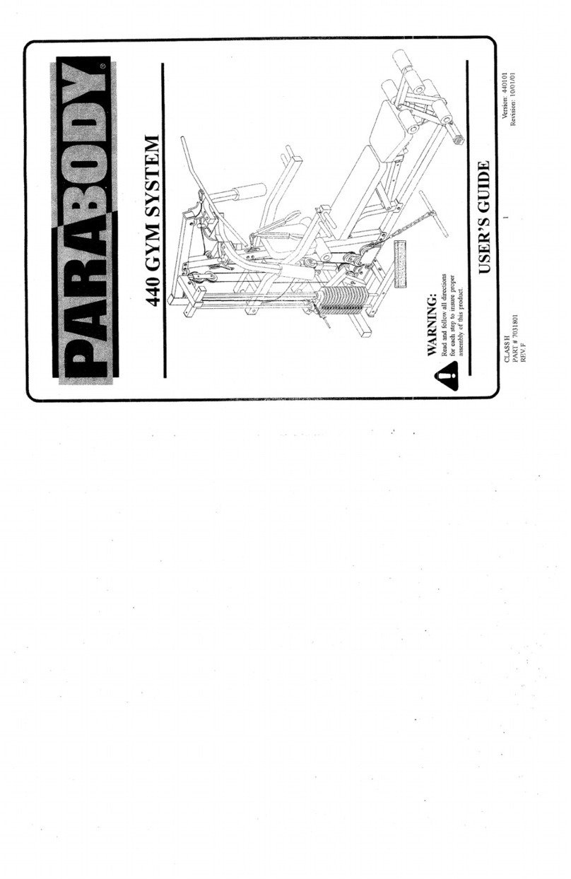
  9. ParaBody 425101 User manual

ParaBody 425101 User manual

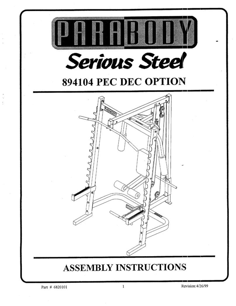
425101 HOMEGYM
ASSEMBLY INSTRUCTIONS
TItANK YOU
FORPURCHASINGTHE 4~5T01 HOMEG~t. PLEASE SAVETI-IESE ASSEMBLYINSTRUCTIONS
FOR YOURPERSONALREFERENCE, ANDADDITIONALSERVICE INFORmaTION.
***IMPORTANT***
’THE#2~10! HO:~,~E GY,~ MUSTBE ASSEMBLEDONA FLAT, LEVELSURFACETO ASSUREITS PROPER.
FUNCTION.
PARABODYINC. STRONGLYRECOMMENDSTHAT THIS PRODUCTBE ASSEMBLEDBY TWOPERSONS TO
AVOIDPOSSIBLE INJURY.
KEEP ALL FRAMECONNECTIONSLOOSE, UNTIL INSTRUCTEDIN THE ASSEMBLYSTEP SEQLrENCESTO
SECURELYTIGHTEN. "
IF YOUEXPERIENCEANYPROBLEMWITH THE ASSEMBLYOF THIS PRODUCT, PLEASE CONTACTYOUR
DEAL~OR YOURPARABODYCUSTOMERSERVICE REPRESENTATIVEAT: 1-800-328-97.I4
TOOLSREQUIRED:RATCHET,3/4 SOCKETor WRENCH,9/16 SOCKETor WR£.NCH,7/’.16 SOCKETor
WRENCH,ADJUSTABLEWRENCH:PHILLIPS SCREWDRIVEl~5/32 ALLENWRENCH,7/32 ALLENWRENCH,
LEVEL, and RUBBEt¢. MALLETor HAMMER-
1
07P...~96
! ! ! A TTENTtON! ! !
........ _U_NL ES_S__Q£HE~ ~ L L
_C_Q_NNETI, N, L ’N, I, T F__._O_N_~
WAS
BOLT LOCKNUT
NOTE: - BOLTLENGTHI$ MEASUREDFROMTHEUNDERSIDEOF THE HEADOF THE BOI.,T. - ....
[BOLT LENGTH ~
BOLT LENGTH RULER:
425101 HOME GYM ASSEMBLY PARTS LIST (LEVEL 1)
SORT AND CODq~"r ALL PARTS BEFORE BEGIIN-NING ASSEMBLY
HARDWARE:NAME/DESCRIPTION
ITEM
1.
2.
4.
6.
7.
g.
9.
.10.
11.
12.
13.
14.
15.
16.
17.
I8.
QTY
I/2X4IN.BOLT................................................................................... ;.............................................................
l
1/2 X 3-I/2 IN.BOLT. .. 2
I~X3IN.BOLT........................................................................ .:.......................................................................
2
.3/8 X4-t/2 IN.THREADEDSHAFT.......................... --.......................................................................................
1
¯3/8X2-.3/4IN.BOLT........................................................................................................................................... l
.3/8X2-I/2IN/BOLT............................................................................................................................. :.............
1
.3/8X2IN.BOLT.................................................................................................................................................
1/2IN.WASHER................................................................................................................................................ 9
.3/8IN.WASHER,........................................... .......................
I/2 IN. LOCKWASHER ’1
1/2IN.LOCKNUT.............................................................................................................................................
1/2IN.LOW~IEIGHT~-~,~.r~u¯ ..................................................................................................................... I
.3/8IN.LOCKNUT............................................................................................................................................... 4
318IN. NUT............................................................................................. 3
.3/8IN.FLANGESPACER................................................................................... -...............................................
2.
I/2 IN. FLANGEBEAKING ’6
2-318IN.CABLEIL~TAININGCLIP.................
;...............................................................................................
5
5-I/2X2-I/2IN.NONSKIDSTR/P..................................................................................................................
19. IXIIN.CAP.R/AGEGUIDE...............................................................................................................................
". ’.LDMENTS/PARTS:
ITEM NAME/DESCRIPTION QTY
BASE..I............................................................................. (6539S01).,..................................................................
PRESSBASE................................................................... (6538601)............................... ~....................................
1
SWIVELPULLEYBRACKET......... ~.............:.............
:(6539101).................................................................... 1
LOWROW/CALFRAISE............................................... (6539301).................................................................... 1
PRESSLEVER................................................................. (~$39001)..................................................................... 1
¯"’~’~03
PRESSSUPPORTTUBE................................................. (6~..9)..................................................................... !...
3-1,~X1 IN.PULLEY................. :.................................
(3116201).................................................................... 7
1. Insert two (2) 1/2 IN. FLANGEBEARINGSinto the SWIVELPULLEYBRACKETas shownon drawing.
AssembletheSWIVELPULLEYBRACKETtothePRESSBASEas shownondrawing,usingore:(I)I~X 4 IN.BOLT,
two(2)I/2 IN. WASHERS,and one (I) I/2 IN. LOCKNUT.frIGHTENTHE CONNECTIONENOUGH
.REMOVETHE PLAY, YET-ALLOWINGTHE SWIVEL BRACKET.TOROTATE.FREELY~
3. SECURELYassemble one (1) 3-1/2 X 1 IN. PULLEYto the SWIVELPULLEYBRACKETas shownon drawing, using
one (1) 3/8 X2 IN. BOLT,two (2) 3/8 IN. WASHERS,and one (1) 3/8 IN. LOCKNUT.
4.
5.
6.
7.
SECURELYassembleone (I) 3-I/2 XI IN. PULLEYto the rear vertic.al flat ofthe PRESSBASEas shownon drawing,
:isi~g-e,ae..(-1-)-3Cg-X-2-2t:N~-BOL-T-,-on~(!) 2,.2#.g.IN,-~ABLE-R,E-T~I~I~one(!) 3/~ _.rN..W.A£HER,-.and-.one(!)
IN. LOCKNUT.
SECURELYassembleone(I)3-I/2X I IN.PULLEYtothePRESSLEVERasshownondrawha~;,usingone(I)318
3/4IN.BOLT,two(2)3/8IN.FLANGESPACERS,andone(1)3/8IN.LOCK
07D/2/96
,Attach two (2) 1 X I IN. CARRIAGEGuIDEsto the underside of the PRESSLEVER,asshownin (DETAIL
Q
I1.
12.
13.
14.
15.
insert two (2) I~ IN. FLANGEBEAR$NGSinto the PRESSLEVERas shownon drawing.
Assemblethe PRESSLEVERto the PRESSBASEas shownon drawing, using one (1) 1:2_ X3-1/’2- IN. BOLT,two(2)
IN. WASHERS,and one (I) I~ IN. LOCKNUT. frIGHTEN THECONNECTIONENOUGHTO REMOVETHE
PLAY, YET ALLOWINGTHE PRESS LEVERTO ROTATEFILEELY)
Insert two (2) 1/2, IN. FLANGEBEARINGSinto the PRESSSUPPORTTUBEas shownon drawin!~.
Assemblethe PRESSSUPPORTTUBEto the PRESSBASEas shownon drawing, using one (1) I/2 X3-I/2 IN. BOLT,
two (.2) 1/2 IN, WASHERS,and one (I) I/2 IN. LOCKNUT.frIGHTENTHECONNEC’rlONEI~IOUGH
REblOVE THE PLAY, YET ALLOWINGTHE PRESS SUPPORTTUBE TO ROTATEFREELY)
A~’tach two (2) :5-.I/2 X2-1/2..IN. NONSKID,STRIPSto the.LOWROW/CALFRAISEapproximately where-shown
drawing.
SECURELYassemble the LOWRow/CALFRAISEto the PRESSBASEusing two ~) b2 X 3 lq,l. BOLTS,three
I/2 IN. WASHERS,and one (I) 1/2 IN. LOWHEIGHTLOCKNUT.
o
SECURELYassembleone (I) 3-1~ X1 IN, PULLE~’~re tbe..r-gnt flat of the BASEas shownon&awing,using one(1)
3/g X 2 IN. BOLT,one (1) CABLERETAININGCLIP,one (1) 31g IN. WASHER,and one (I) 3/1| IN. LOCK
SECURELYassembletwo (2) 3,1/2 XI IN. PULLEYSto the middle fiat of the BASEas shownin ,~ETAILB), using
one (I) 3/8 X 4-1~ IN. THREADEDSTUD,two (2) CABLERETAININGCLIPS,and two (2) 3/8.2~.
SECURELYassembleone (1) 3-1/2 X1 IN. PULLEYSto the rear flat of the BASEas shownon dr~twing,using one (1)
3/8 X2-I~ IN. BOLT,one (1) 2-3/8 IN. CABLERETAININGCLIP,one (1) 3/8 IN. WASHER,and one (1) 3/8 [N. ,~U77..
THIS CONCLUDES THE ASSEMBLY OF (LEVEL 1)
425101 HOMEGYMASSEMBLYPARTS LIST (LEVEL 2)
COUNTA1.L PARTS BEFOREBEGINNINGASSEMBLY
I--IAR~WARE:
ITEM
1.
2.
3.
4.
5.
6.
7,
g.
9.
I0.
I1.
12.
13.
NA.ME/DESCRIPTION QTY
3/$X2IN.BOLT................................................................................................ :............................:....................
I
~/8X~-~/4IN.BOLT.......................................................................................................................................... 2
3/8X3IN.BOLT..................................................................... ~..........................................................................
$
I/2X3-1/4IN.BOLT............................................................................................................................................ 4
3/8IN.WASHER............................................................................................................................................... 19
1~IN.WASHER................................................................................................................................................... 8
3/8 IN. LOCK.NUT " 11
I/2IN.LOCKN,UT.................................................................................................................................................4
318IN.SPKINGPINA:SSEMBL~/"....................................................................................................................... 1
9/16MUSHKOQMCAP....................................................................................................................................... 2
THUMBSCREW................................................................................................................................................... 1
3/8IN.FLANGESPACER..................................................................................................................................... .29
2-7I$IN.CABLERETAININGCLIP..................................................................................................................... I
WELDMENT$/PARTS: ""
,.:~EM NAM.E/DESCRIPTION QTY"
",~.. REARUPRIGHT............................................................ (6538501).................................................................... I
2. MIDDLEUPRIGHT....................................................... (6~30303).................................................................... I
3. FR.ONTUPRIGHT.......................................................... (6540001).....................................................................
~:’ ROLLE~.PADSHAFT..............................
i....................(6435301).................................................................... l
-5.. ROLLERPAD.................................................................
(6194601).................................................................... 2
~. 3-l/2X! iN.PULLEY.................................................... (3116201).....................................................................
!
?........ 4-I~XI IN.PULLEY................................................... (311610~)....................................................................
1
LOOSELYassembletheFRONTandMIDDLEUPRIGHTStotheBASEas shownondrawing,usingfour(4)31gX 2 IN.
BOLTS¯eight(8)3/8IN.WASHERS,andfour(4)3/8IN.LOCKNUTS.
LOOSELYassembl~theREARUPRIGHTtotheBASEasshownondrawing,usingtwo(2)I~3.1/4 IN. BOLTS, four
(4)l~I"N.WASHER.S,andtwo(2)I/2.IN.LOCKNUTS.
LOOSELYassembleth~PRESSBASEtotheREARANDMIDDLE’UPRIGHTS,usingfour(4)~/gX 3 IN.BOL’I~,
.eight(g)3/8IN.WASHEP,.S,andfour.(4)3/gIN.LOCKNUTS.
i~OOSELY.assemblethePRESS:BASE:totheBASEasshownondrawing,usingtwo(2)IP-X 3-I/4IN..BOLTS¯four(4)
I/2.rN.WASHERS,andtwo(2)l~ IN.LOCKNUTS.
SECURELYassembleone(I)3-I/2X 1 IN.PULLEYtotheFRONTUPRIGHTas shownondrawing,usingone(I)
X 2-314IN.BOLT,two(2)31gIN.FLANGESPACERS,andone(I)31.gIN.LOCKNUT,.........
SECURELYassembleone(I)31gX 2-3/4IN.BOLT,two(2)318IN.WASHERS,andone(I)318IN..LOCKNUT
FRONTUPRIGHTintheholeabovethepullsyassembledinSTEP4.
.SECURELYassembleone(I)318IN.SPRINGPINASSEMBLYto the SPRINGPINHOUSING,of’theFRONT
UPRIGHTas shownin (DETAILA). (IllIMPORTANT!!! TIGHTENTHENUT OF THESPR]ING
ASSEMBLY SECURELY)
o
10.
A~tachone(I)THUMBSCREWto theFRONTUPRIGHTas.shownon drawing.
Assembletwo(2)ROLLERPADSto theFRONTUPRIGHTas shownon drawing,usingone(I)ROLLER
SHAFT,andtwo(2)9/I6 M’USHROOMCAPS.
SECURELYassembleone(I)4-I/2X I IN.PULLEYtotheHORIZONTALFLATo’fthePRESSBASEusingone(1)
.~/$X 2 IN.BOLT,one(I)2-7/8IN.CABLERETAININGCLIP,one(1)3/8IN.WASHER,andone(1).3/~IN.
NUT.
THIS CONCLUDESTHE ASSElVIBLY OF (LEVEL 2)
425101 HOMEGYMASSEMBLYPARTS LIST (LEVEL
COL".’NT ALL PARTSBEFOREBEGIN’NINGASSEMBLY
.H,~RDWARE:
ITEM NAME/DESCRIPTION QTY"
~/8Xl-1/2IN.BOLT...........................................................................................................................................I.
2. .~/~X2-I/4IN.BOLT........................................... ’.................................................................................................
.% .~/I~X2-2/4IN.BOLT.............................................................................................................................................
~. 3/~X 3 IN.BOLT .......................................................6
~. T~~’X’~"-~.’BOLT,...................................................................................................................................................
( I~X3-114BOLT................................................................................................................................................... 1
6~,’ 314IN.WASHER....................................................................................................................................................
7. I/2IN.WASHER....................................................................................................................................................
5
8. 3/~ IN.WASHER "
9. 3/8 IN. LOCK WAS~ER
~0.
1I.
12.
I3.
16.
17.
18.
19.
20.
21.
2.3.
I~IN.LOCKWASHER.......................................................................................................................................
I
.3/8IN.LOCKNUT.............................................................................................................................................
g
I~IN.LOWHEIGHTLOCKNUT......................................................................................................................
2
WEIGHTSTACKSELECTORPiN"....................................................................................................................
I
GUIDERODPIN................................................................................................................................................
2
.3/8IN.FLANGESPACER.....................................................................
,.......
j....................................................
6
WEIGHTPLATEBUSHING.........................................................................:..................................................
.30
WEIGHTSTACKCUSHION...............................................................................................................................
2
9/I6MUSHROOMCAP.,...............................................:....................................................................................
4
I~IN.FLANGEBEARING................;...................................................................................................;.............
2
.3/8IN.SPRINGPINASSEMBLY.........................................................................................................................
I
I’-I/4IN.SQ.RUBBERBUMPER...............................................:.........................................................................
I
PARAGLIDBSTRIP.....................................................:...............~.......................................................................
16
PLASTIC.WASHER...............................................................................................................................................
2
WELDMENTS/PARTS:
ITEM NAME/DESCRIPTION QTY
I. .TOPBOOM..............................................
"’9
2. GUIDEROD...................................................................(6~.3401)....................................................................
2
3. ..w~!~H’rST,ACKSPACER........................................... (6375903)................................................................... "~
4. WEIGHt"PLATE............................................................
(6,14501).................................
~................................
15
5. WEIGHTSTACKSFL~.FT............... ; ..............................
(6,66001).................................................................... I
6. HEADPLATE.......... ~’...........................................(622300I)...................................
7. WEIGHTSTACKLABELS........................................... (6189501)..................................................... ; ..............l
8. 3-I~XI IN.PULLEY................................................... (3116201).................................................................... .3
9. 4-I~X1IN.PULLEY.. .................................................. (3116102)....................................... ~............................
l
10. PAD,13-1/2,X10-1/2....................................................... (6457301).......... : ..........................................................1
I1. ROLLERPAD.................................................................. (6194601).....................................................................4
)" ROLLERPADSHAFT....................................................(6.485301).....................................................................2
"ADJUSTABLEROLLERPADSLEEVE........................ (6.16702).....................................................................I
I-~. PECSEAT..................... , ..................................................(6539901)..................................................................... I
13. LEGCURL/EXTENSION............................................... (6540101):.......... :.........................................................
I
[, :-..’THE INSTRUCTIONSF O R" (LEI/T, L i’~)’.’AR.E’.-~ BE:IJSED WlTH.THE. (ZF, I/ ~’r..~..DRA .W .L~. .G ) ~~
I. LOOSELYItssemble three (.3) 3-1/2, X I IN. PULLEYS,one (1) 4-I/2, X1 IN. PULLEYto the inside ofthe TOP
as shownin (DETAILA), using three (.3) 3/8 X2-3/4 IN. BOLTS,one (1) 318X2-II4 IN. BOLT,six (6) 3/8 IN.
SPACERS,two (2) 318 IN. WASHERS,and four (4) 3/8 IN. LOCKNIYI’S.
2. _.LOOSELYresemble the TOPBOOMto the top ofthe REAR.MIDDLE,and FRONTUPRIGHTSas shownon oh-awing,
using.four (~) 3/8 X3 IN. BOLTS,two(2) I~ X3 IN. BOLTS,eigh.t (8) 3/8 IN. WASHERS,three (3) I/’2. IN.
one (I) I/2 IN. LOCKWASHER,four (4) 3/8 IN. LOCKNUTS,and one (I) I~ IN. LOWHEIGHT]LOCK
3. Insert the GUIDERODSinto the BASEas shown on drawing. (NOTE:LUBRICATEGUIDERODSWITH
¯ SILICON OR TEFLONSPRAYTHAT’ISAVAILABLE.ATIMOST HARDWARESTORES)
NOTE: THETWO(2) WEIGHTSTACKSPACERS,ANDTHETWO(2) 3/4 IN. WASHERSIN STEP 5 ARETO BE
WHENASSEMBLINGA 150 LB. STACK. IF ASSEMBLINGA 200 LB. STACKAT THIS TIMEPLEASE
DISCARDTHESE ITEMS.
6. Slidet~o(2) WEIGHTSTACKSPACERS,two3/4 IN.WASHERS,andtwo(2)WEIGHTSTACKCUSHIONS
...........(-’RADIUSEDGEFACINGUP)
~ :’E: THEWEIGHTSTACKSHAFFhN STEP 6 IS TO BE USEDWHENASSEMBLINGA I50 LB. STACK.IF
......"ASSEMBLINGA 200 LB. STACKAT THIS TIME PLEASEDISCARDTHIS ITEM ANDREPLACEWITHTHE
WEIGHTSTACKSHAFTUSEDIN THE(50 LB. ADD-ONKIT 359101).
07/2.2/96
SECURELYassemble the WEIGHTsTACKSHAFTto the HEADPLATEas shown on drawing, using one (I) 3/2 X
1~ IN. BOLT,one (1) 3/8 IN. LOCKWASHER,and one (I) 3/8 IN. WASHER.
Snaptwo(2)W3~IGHTPLATEBUSHINGSeach,intofiReen(}5)WEICHTPLATESshownin(DETAIL B).(IF
ASSEMBLINGA 200 LB. STACK AT THIS TIME, SNAP TWO (2) WEIGHTPLATE BUSHINGSEACH INTO
THE RE.~tAININGFIVE(S) WEIGHTPLATES)
USINGEXTRE~TECAREslide all fifteen (or twenty) WEIGHTPLATESdownover the CUIDIERODSonto the
WEIGHTSTACKCUSHIONSas shown on drawing. (MAKESURETHATTHEKEYHOLESOF THEWEIGHT
PLATES ARE ALL FACING THE SAME WAY)
Slide t~e HEADPLATEASSEMBLYdownover the GUIDERODSonto the WEIGHTSTACKas shown on drawing.
Swingth~ GUIDERODSunder the TOPBOOMas shownon drawing, and hold in place with two (2) GUIDERODPINS.
¯Auach the-WEIGHTSTACK-LABELSto the ..W.EIGHTSTACK:asshown on.drawing. Also .insertthe WEIGHTSTACK
SELECTORPIN into the first WEIGHTPLATTEof the WEIGHTSTACK.
II.
12.
SECURELYAssemble one (I) ~/8 IN. SPRINGPIN ASSEMBLYto the SPRINGPIN HOUSING,of the LEG
CURL/~XTENSIONARMas shown in (DETAILC). (Ill IMPORTANT!!! TIGHTENTHENUTOFTHESPRING
PIN ASSEMBLYSECUREL@.
Attach eight (8) PAKAGLIDESTRIPSto the AD.IUSTABLEROLLERPADSLEEVEas shownin (DETAILD),
.usingthe. followingsteps:
¯Thoroughlyclean all surfaces wherethe PARAGLIDESTR/PSare robe attached.
~.Removethe PAKAGLIDESTRIPSfromthe paper backingand firmly apply themto all showasurfaces.
13.
15.
16.
17.
Removethe 2 IN. SQ. ENDCAPfrom the bottom of the LEGCURLEXTENSIONAR~,I, pull back the SPRINGPIN, and
Insert the ADJUSTABLEROLLERPADSLEEVEas shownin (DETAILE). Release the SPKI’NG,PINinto one of the
adjustmentholes, andreinsert the 2 IN. SQ,ENDCAP.
Assemblethe two (2) ROLLERPADSto the LEGCURLEXTENSIONARMas shownon drawing using one (I)
ROLLERPADSHAFT,two (2) PLASTICWASHERS,and two (2) 9/I 6 MUSHROOMCAPS. (MAKESURE
THE ROLLERPAD SHAFT IS INSERTED THROUGHLARGEHOLEON THE ADJUSTABLEROLLERPAD
SLEEVE)
¯ AssembletheLEGCURI./EXTENSIONARMtotheFRONTUPRIGHTusingthefollowings~eps:
¯". Insert twO(2) 1/2 IN. FLANGEBEARINGSto the FRONTUPRIGHTas shownn drawing..
¯Assemble the LEGCURL/EXTENSIONARMto the FRONTUPRIGHTas shoumon drawing, using one (I) I/2
X3-I14 IN. BOLT,two (2) I/2 TN.3k’ASHERS,and one (1) I}2 IN. LOWI-I~IGI-IT LOCKNUT.(TIGHTEN
CONNECTIONENOUGHTO REMOVETHE PLAY, YET ALLOWINGTHE LEG CURL/EXTENSiON
ARMTO ROTATEFREELY)
¯* Attach one (1) 1-1/4 IN. SO..RUBBERBUMPERto the FRON’rUPRIGHTwhcr~ the LEGCURL/EXTENSION
ARMmakes contact. (SEE DRAWING).
Pre-.assemblethePECSEAT,usingthefollowingstep’s:
¯:SECURELY~assembleoneof.theBACK/SEAT.PADStothePEG.SEATasshownondrawing,usingtwo(2)318
3 IN.BOLTS,two(2)3/8I"N.LOCKWASHERS,andtwo(2)3/8IN.WASHERS.
Assembletwo(2)ROLLERPADStothePEGSEATas shownondrawing,usingone(I)ROLLERPADSHAFT,
andtwo(2)9/I6 MUSHROOMCAPS.
__I_3.:........A.~.n.~c/~ht(8)PAP,.AGLIDESTR.IPStotheFRONTUPRIGHTasshownin(DETAILF),andusilngthedirections
followed ~n step I2. "
’,...... Pull back the SPRINGPINon the FRONTUPRIGHTand insert the PEGSEATdownto desired height. Release the
SPRINGPINandallow it. to engageinto the adjustment.holes. Use the THUMBSCREW~o tighten the PEGSEATin
place.
THIS CONCLUDES TIIE ASSEMBLY OF (ZEFEL
425101 HOMEGYMASSEMBLYPARTS LIST
COUNTALL PARTSBEFOREBEGINNI!NGASSEMBLY
HARDWARE:
ITEM .NAME/DESCRIPTION QTY
7.
$.
9.
I0.
11.
12.
13.
14.
¯ 318X’3IN..BOLT......................... ~.....................................................
:..........................~.......................................
2
I/2X3-’I/2IN~’BOLT................................................................................................................... ~......................1
1/2X4IN.BOLT................................................................ ~:.................................".......................~....., ..............1
318IN.WASHER......................................... ~...~....................................................................................................2
1/2IN.WASHER..................................................................... ;............................................................................4
3/8IN.LOCKWASHER.................................................................. 2...................................................................2
1/2_ IN. LOCKNUT " " " , "2
CONTROLLEVER ,1
3/4 IN. FLANGEBEARING ’2
I/2IN.FLANGEBEARING................................................................................................ ................................ 4
3/8l’N.JOINTCONNECTORCAP............................................................ :........................................................2
#8INT.TOOTHLOCKWASHER.................................................................................................................... : 2
8-32 X 3/16 IN. SCREW ’2
E-KING...........................................................................................................
5/16X3/8IN.SETSCREW................................................................................................................................ 2
PARAGLIDESTRIP............. ~................................, .............................................................................................
8
4IN.VINYLSLEEVE......................................................................................................................................... 1
ADHESIVECLIP................................ ’...............
~.................................................................................................
1
WELDMENTS/PARTS:
ITEM NAME/DESCRIPTION QTY
I. PRESSARM...................................................................
(6538401)................................................... ."................
I
2. RECEIVINGTUBE........................................................ (6539201).................................................................... 1
3. PRESSADJUSTMENTTUBE.......................................
(6534602)....................................................................
I
"4. I0-I/4IN.AXLE...............................................~......~......(62{]~-601);:.....................".....................................
.’.......
I
5. PAD,IS-ira.X10-1/2........ ~............................
,:...............
(6457301).....................................................................
1
I. Inse~t the PUSH/PULLCABLEthrough the bottom .oftheRRESSARMup to the CONTROLLEV~-’Ras shownin
.(DETAILA), and hold in pla~e with one (1)E-RING.
2. SECURELYassemble the PUSH/PULLCABLEto the CONTROLLEVERas shownin (DETAILA), using one (1)
IN. JOINTCONNECTORCAP,one (I) #8 INT. TOOTHLOCKWASHER,and one (1) 8-32 X 3/16 IN. SCREW.
Slide one (I) IN. VI NYL SLEEVE over th e CONTROL LEVER. Then SECURELY assemble th e CONTROL LEVER to
the_TA.R.at~.tha/~EfiSARM..~s~ho.wm_ia.(DETAIL_K)Ja~u~omwd,/l/iS_lh[,JD[hEL~OBlq!CZD~’,..CKP.~n~..CD,.~-.I’ST........
TOOTHLOCKWASHER,and one (I) 8-32 X 3/16 IN. SCREW.’
Attach four (4) PAPA.GLIDESTRIPSinside the end of the RECEIVINGTUBE,and four (4) PAPA.GLIDESTRIPS
ou~ide the end of the PRESSADJUSTMENTTUBEas shownin (DETAILB), using the followin@steps:
¯Thoroughlyclean all surfaces wherethe PARAGLIDESTRIPSare to be attached.
07P_2~6
10.
I1.
12.
14.
’ ~* Removethe PAPA.GLIDEST/UPSfromthe paper backing and firmly apply themtO all shownsurfaces.
,Carefully slide the PRESSADJUSTMENTTUBEinto the RECEIVINGTUBE.(MAKESURE"],’HESPRINGPIN
BARRELON THERECEIVINGTUBEIS ONTHE SAMESIDE AS THEHOLESIN THEPF~SS ADJUSTM~IlNT
TUBE)
Insert two (2) 1/2- IN. FLANGEBEARINGSinto the PRESSLEVERas shownon drawing.
Assemble the PRESSADJUSTMENTTUBEto the PRESSLEVERas shown on drawing, using one (1) 1/2 X
BOLT,two (2) 1/2 IN. WASHERS,and one (1) I/2 IN. LOCKNUT.(TIGHTEN THECONNEL-i’IONENOUGH
TO .REMOVETHE PLAY, YET ALLOWINGTHE RECEIVING TUBE TO ROTATEFREELY)
Insert two (2) .3/4 IN. FLANGEBEAP,.INGSinto the PRESSARM~s shownon the drawing.
¯ ’. Holdthe PRESSARMbetweenthe. REARand ~MIDDLEUPRIGHTSas shownin on drawing, and’sIide the I0-I/4 IN.
AXLEthroughthe MIDDLEUPRIGHT,th~PRESS.A~RM,:and.througfi the COLLARon.the REARUPRIGHT.To
SECUREthe AXLEin place, insert two (2) 3116 X3/8 IN. SETSCREWS,into the COLLARSon the UPRIGHTSand
tighten it downonto the AXLE.(SEEDETAILC)
Insert two (2) I~ IN. FLANGEBEARINGSinto the RECEIVINGTUBEas shownon drawing.
Assemblethe RECEIVINGTUBEto the PRESSARMas shownon drawing, ~tsing one (1) I/2 X 3.-I/2 IN. BOLT,two
1/2 IN. WASHER.S,and one (I) 1;2 IN. LOCKNUT. (TIGHTENTHECONNECTIONENOUGItTO REMOVE
PLAY,.YET ALLOWINGTHE PRESS ARMTO ROTATEFREELY)
Assemble the PUSH/PULLCABLEto the SPRINGPIN HOUSINGand to the L-BRACKETon fl~e RECEIVING
TUBEas shownin (DETAILD), using the f’ollowing steps:
¯Threadthe first I/4-2~i IN. NUTto the bottomof the threadedendof’the CABLE.Allow
¯other I/4-28 IN. NUTto hangloose on the exposedCABLE.until the SPRINGPINASSEMBLYis attached.
¯Securely assemble the SPRINGPIN ASSEMBLYto the SPRINGPIN BARREL.(!:! IMPORTANT!!!
TIGHTENTHE NUT OF THE SPRING PIN ASSEMBLYSECURELY)
¯Swingthe PRESSARMup until the SPRINGPIN of’the PUSH/PULLCABLEengages in one of the
adjustmentholes.
¯Threadthe secondI/4-25 IN. NUTonto the threaded end of the CABLE,and cinch the two(2) 114-2~.IN.
aroundthe fiat.
¯ Usethe extra thread on the end of.the CABLE’toadjust out slack, ( !!! DONOTADJUSTOUTTOFAR1!!
ALWAYSALLOWSPRING PIN ASSEMBLYTO FULLY ENGAGE)
¯Attach one (1) ADHESIVECLIPto the RECEIVINGTUBEand snap the CABLEinto it.
"SECURELYtighten all loose frame cormectiot~s madeto this point. (!!! IMPORTANT!!! TOASSUR~PROPER"
.:~FUNCTION OF THE 425, THE LOOSEFRAMECONNECTIONSMUSTBE TIGHTENEDIN THE FOLLOWING
ORDER)Tighten the:
¯ REARUPRIGHTto the BASEand to the TOPBOOM.
¯ PRESSBASEto the REARand MIDDLEUPRIGHTS.
¯ PRESSBASEto the BASE.
.= MIDDLEUPRIGHTtothe BASE’andto the .TOPBOOM.
¯ FRONT.UPRIGHTto the.BASE.
NOTE: DO NOT TIGHTENTHE FRONTUPRIGHTTO THE TOP BOOMAT THIS TIME,
SECURELYassemble the other BACK/SEATPADto the FRONTUPRIGHTas shownon drawing, using two (2) 3/~
.3 IN. BOLTS,two (2) 3/8 IN. LOCKWASHERS,and two (2) 3/g IN. WASHERS.
THIS CONCLUDESTHEASSEMBLYOF (LEVEL 4)
9
07/22/96
425101 HOMEGYMASSEMBLYPARTS LIST (LEVEL S)
COUNT ALL PARTS BEFORE BEGINNING ASSEMBLY
ITEM NA~ME/I)ESCRIPTION QTY"
1. 3/8 x 2 IN. BOLT 2
2. 3/8X2-3/4IN.BOLT............................................................................................... ;...........................................
4
3. 318X3IN.BOLT..............................
4. I’/2X3-I~IN.BOLT..............................................................................................................................................
3
5. 3]8IN.WASHER,................................................................................................................................................
6. 1/22.IN.WASHER.......
-..................................................."-......................................................................................6
7. .3/.8IN.LOCK.WASHER..........................................................................................
’...........................................4
8. ,3/4.IN.THRUST,WASHER..............
~."............................................
:.............................................
:£.i................2
9. 3/8IN.LOCKNUT.................................................................................................................................................
2
I0. I/2IN.LOCKNUT..................................................................................................
:.....
:........................................
3
II. I/2-IN.FLANGEBEARING.............................
~...................."................................................................................
2
12. 3/4IN.FLANGEBEARING............................................................................................................................... 4
13. 2-3/8IN.CABLERETAININGCLIP.................................................................................................................. 2
14; "’" """ "" "" "t;
,~,
:,~,~~~~....................................................................................................................................................
~-~. ..
15. 3/gIN.SPRINGPINASSEMBLY.......................... 2............................................................................................3
16. 1/2IN.SPRINGPINASSEMBLY.............................................. 2.........................................................................1
17. THUMBSCREW............. : ..............................................
2........................................................................................1
18. PARAGLIDESTRIP...............................................................................................................................................
19. 1X1IN.CARRIAGEGUIDE..............................................................................................................................
20. 2IN.PULLEY............. 2...........................................................................................................................................
2I. 3 IN. WHEEL ’2
"~’~ 3/8X’I/4IN.SPACER.........................................................................................................................................
:2
V,~ELDMENTS/P ARTS:
ITEM. NAME/DESCRIPTION QTY
2. ADJUSTABLEPRESSSEAT................:.......................
(6538901)..............................................
3. PECCAM................................................
:...........
:...........
(6~2~702).....................................................................
4. CENTERPULLEYBRACKET...................................... (6~30203).....................................................................
~. BEARINGHOUSING...................................................... (6~9601)...,................................................................. I
6. LEFTPECARM............................................................. (6ff~97__O!)~...................................................................
1
7, RIGHTPECARM.......................................................
L..(6529801).....................................................................
I
8. BACKPAD............................................................. ’.........(6433701)................... , ............................
-.J.~..............1
9. SEATPAD...................................................................... (64~3~01)..................................................................... 1
10." 3-1".2XI IN.PULLEY.......................................... ~.........
(3116201).....................................................................
lI. 4X.12IN.ROLLERPADS . ............................................
(61"~6,01)"......................................................................
I. Pre-assemblethePRESSBACKSUPPORTusingthefollowings~eps:
¯ Attacheight (8)PARAGLIDESTRIPSto thePRESSBACKSUPPORTasshownin
(DETAILA),usingthtfollowingsteps:
¯ Thoroughlyclean all surfaces wherethe PARAGLIDESTRIPSare to be attached.
¯Removethe PA~t.-~-CID-E-STPd’PS
-fff~-the Pap’elr’b~ffd" ~-u"miY apply themto aii-~ii~n si~/aces.
¯ SECURELYassembleone(I)3/gIN.SPRI’NGPINASSEMBLYtotheSPRINGPLNHOUSING,of~h¢
PRESSBACKSUPPORTas shownin (DETAILB). (!!!IMPORTANT!!!TIGHTEN’THENUT OF
"SPRING PIN ASSEMBLY SECURELY)
¯SECURELYassemble~o (2)3 IN.WHEELStothePRESSBACKSUPPORTas shownoni drawing,using
two(2) 3/8 X2-3/4 IN. BOLTS,two (2) 3/8 IN. WASHERS,.and two~) 3/8 X 1/4 IN. SPACERS.(IF 10
07.~2/96
WHEELS DO NOT ROTATE FREELY AFTER THE BOLTS ARE TIGHT, REMOVE WASHERS.)
SECURELYassemble~heSEATPADtotheADJUSTABLEPRESSSEATasshownon/rzwing,usingtwo(2)3;8X
314IN.BOLTS,two(2)318IN.LOCKWASHERS,andtwo(2)318IN.WASHERS.
PullbacktheSPRINGPrNon thePRESSBACKSUPPORTand.slidetheADJUSTABLEPRESSSEATintothe
RECEIVINGW’ELL.EngagetheSPRINGPINintooneof theadjustmentholes.SecuretheADJUSTABLEPRESSSEAT
in place with one (1) THUMBSCREW.
SECURELYassembletheBACKPADt6thePRESSBACKSUPPORTasshownondrawing,usingtwo(2)3/8X 3 IN.
BOLTS,two(2)3/~IN.LOCKWASHERS,andtwo(2)3/8IN.WASHERS.
Inserttwo(2)I/2IN.FLANGEBEARINGSintothePRESSSUPPORTTUBEasshownon drawing.
"..SECURELY"assemble.thePRESSBACKSUPPDRTto the.PRESSsuPPORTTU.BE,~sshownindrawing;usingone(I)
I~.X3~I/’2IN.:BOLT/:two"(2)I/2IN.~W.ASHERS,.~m~done(I)I/2IN~.LOCKNUT.(~IGHTENTHECONNECTION
ENOUGH TO.REMOVE’THE:PLAY,~/ET.ALLOWINGTHEPRESS BACK SUPPORT..TO ]ROTATE FREELY)
SECURELYassembleone(I)ID_I~ SPRINGPIN.ASSEMBLYto theSPRINGPINHOUSING,of thePRESS
SUPPORTTUBERs shownin (DETAILE). (!!!IMPORTANT!!!TIGHTENTHE NUTOi~ .THESPRING
ASSEMBLYSECUILI’.LY)"~...................... -’
SECURELYassemble, the BEARINGHOUSINGand the CENTERPULLEYBRACKETto the ]FRONTUPRIGHT~s
shown.ondrawing, using two(2) 1/2 X3-1/2IN. BOLTS,four (4) I/2 IN. WASHERS,and two (2) 1/2 IN. LOCK
(THE CONNECTORPLATES ON THE BEARING HOUSINGANDTHE CENTER PULLEY BRACKETHAVE
SLOTTEDHOLES. SHIFT THE BEARINGHOUSINGDOWNANDTHE CENTERPULLEYBRACKETUP AS
FAR AS POSSIBLE)
o¯
Assembletwo(2)3/4IN.THRUSTWASHERSandtwo(2)PECCAMStotheLEFTandRIGHT:FECARMS,as shown
¯ondrawing.
Insert four (4) .3/4 IN. FLANGEBEARINGSinto the BUSHINGSof the BEARINGHOUSING,as shownon drawing.
ll. InserttheLEFTandRIGHTPECDECARMSthroughthe3/4IN.FLANGEBEARINGSin theBEARINGHOUSING
ontheirrespectivesidesasshownondrawing,andSECURE~heminplacewithtwo(2)3/4I.D.STARLOCKCOLLARS.
12. ¯..Attach two (2) 1 X 1 IN. CARKIAGEGUIDESto the ANGLEon the BEARINGHOUSINGwhere the PECCAMS
,makecontact with the ANGLE.
.Slidet~,.o(2)4 X 12ROLLERPADSontothe LEFTandRIGHTPE’C.D~.C’ARMS,umirtheROLLERPADisFLUSH
,~iththe bottomof.theARMS.(IF A LUBRICANT-ISREQUIRED,COATTHE INSIDEOF THEROLLERPAD
"WITH RUBBING ALCOHOL ALSO, ROTATING THE PAD WHILEP.USHINGUP WILL HELP TO EASE
’ASSEMBLY)
14. SECURELYassembletwo(2)3/8IN.SPRINGPINASSEMBLIESto theSPRINGPINBARRELS,ofthePECCAMS
sho,h’nin (DETAILB). (!!!IMPORTANT!!! TIGHTENTHE NUTOFTHE SPRINGPIN ASSEMBLYSECURELY)
15. PULLEYBRACKETasshownin(DETAILD),usingtwo(2)3/8X 2 IN.BOLTS,two(2)3/$IN.WASHERS,and
(2) 3/8 IN~ LOCK NUTS.(NOTE:THIS CONNECTIONWILL BE TIGHTENEDAFTER THE CABLEHAS BEEN
ROUTED)
.... placewiththree(.3)I/4.IN.CAPNUTS.
THIS CONCLUDES THE ASSEMBLY OF (LEVEL
425101 HOME GYM ASSEMBLY PARTS LIST .(LEVEL’6)
LOOSELY’asscmble.two(2)3-I~X 1 IN..P.ULLEYSandtwo(2)2-3/,~IN,CABLERETAININGCLIPStotheCENTER
II
07~6

COUNT ALL PARTS BEFORE BEGINNING ASSEMBLY
ITEM NA~[E/DESCRIPTION QTY
""’", I/4IN. WASHER 1
.,.. I!,1-28IN.NUT....................................................................................................................................................
2
.3. KEYHOLECLEVIS............................................................................................................................................
2
4. SNAPLINK............................................................................................................................
..............................
2
~,VELDMENTS/PARTS:
ITEM NAME/DESCRIPTION QTY
1. D-P.ING........................................................................ :..(6540301)........................ ,........................., ................1
2. D-RINGCABLE...: ....................................................... :.(656890"I).~.................................................................. i
3. .LATCABLE.................................................................... (6535901).................................................................... !
4. ,,MULTI-PKESS,CABLE...................................................
(653600.1.).................................................:.................
I
* ~T.H.E~.S~rRUC’T.ION..S.~FOR(/,,E.. V~J,,"6) ,~RF~To~BE,.USED
1. Toassemblethe D-RINGCABLE,follow the cable routing diagramshownin (DETAILA), and use.the following steps:
¯SECURELY’assemble the D-RINGCABLEto the WEIGHTSTACKSHAFTof the HEADPLATEas.shown on
drawing. -. ""-"....................
¯Route the CABLEup and over the two (2) PULLEYSin the LATBOOMabbve the WEIGHTSTACK.
(REMOVEPULLEYSFOR EASE OF INSTALLATION)
¯LOOSELYassemble the D-RINGto the D-RINGCABLEas shownon drawing, using one (I) 1/4 IN. WASHER,
and two (2) 1/4-28 IN. NUTS.(LOCATE1/4-28 NUTSHALFWAYUP ONTHETHREADSOF THED-RING
CABLE. DO NOTTIGHTENNUTSAT THIS TIME)
*SECURELYTighten the two (2) PULLEYconnections from the SECONDSTEP.
2To.assembletheLATCABLE,followthecableroutingdiagramondrawing,andusethefollowingst~.’ps:
¯ . Attachone(I)SNAPLINKtotheballendoftheLATCABLE.
¯RemovethetwoboltsintheFRONTUPRIGHTandTOPBOOMconnection.
.. RoutetheLATCABLEas shownon drawingandin (DETAILB).(REMOVEPULLEYSFOREASE
INSTALLATION)
¯RuntheLATCABLEthroughtheholeoftheD-RINGasshownin(DETAILB)andattachone(I)KEYHOLE
CLEVIStotheendoftheLATCABLE.
,* ReplaceandSECURELYtightenthetwo(2)PULLEYandtwo(2)BOLTcomiectionsfromtheprevioussteps.
(IMPORTANT:NL-kKE SURE THE LAT CABLE RUNS OVER THE TOP OF THE BOLTS IN THE TOP
BOOM!!!)
¯ ..’toassembletheMULTI-PRESSCABLE,followthecableroutingdiagramshown.indrawingandusethefollowingsteps:
¯Attach one .(I) SNAPLINKto the ball end of the MULTI-PRESSCABLE.
¯Runthe MULTI-PRESSCABLEthrough the hole of the D-RINGas shownin (DETAILB) a6d attach one (I)
KEYHOLECLEVISto the end of the MULTI-PRESSCABLE.
THIS CONCLUDES .THE.ASSEM.BLY-OF(LEVEL 6)
425101 HOMEGYMASSEMBLYPARTSLIST (LEVEL 7)
COUNT ALL PARTS BEFORE BEGINNING ASSEMBLY
iTEM
I.
4.
5.
6.
7.
g.
9.
10.
NAME/D ESCtLIPTION QTY
3/8xl IN.BOLT........................................................................ ~.....................................................................1
318X2IN.BOLT............................... :.......................... .....................................................................................I
S/gX2-I/4IN.BOLT....................................................................................................................................... 2
1/4IN.WASHER................................................................................................... ~..~.........................................
2
3/8IN.WASHER................................. ,..,...........................................................................................................
1/4-2gIN.NUT.................................. -............................................................................................................~..2
3/8IN.LOCKNUT............................................................................................................................................ 4
SNAPLINK....................................................................................................................................................... I
I~EYHOLECLEVIS....................................................
PULLEYBRACKET.................................................................... :. ...................................................................
1
,VCELDMENTS/PARTS:
ITEM
I.
2.
3.
5.
NAME/DESCRIPTION QTY
3-1/2x1IN.PULLEY................................................... (31i6201).................................................................... 3
PECDECCABLE........................................................... (653S601)................................................................... : I
ABCABLE...................................................................... (653S801)............ -.;.....................................................1
LEGCABLE.......................................................... ..........(6569001)................. ~............~.............................. I
5-I14 IN, PLATES.... ; .....................................................(6013703)................................... .; ...............................
2
FOmaZrZ~~~:AR~.~O..~E.~trSE~..wr_7ni.~.z!
I .-. . Toa~scmblethe PECDECCABLE,follow ~c cable routing dia~ on d~wing,~d use ~e following steps:
¯Assemble each end of the PECDECCABLEto ~e ~ECCAMS.
- Dmp~ ~e CABLEover ~e P~LEYS on ~c CENTERPULLEYB~C~T. ~HIS WILL FO~I A LOOPIN
THE CENTEROE THE CABLE)
~*Positiqn .the CABLERETAININGCLIPSin a 45 DEGREEposition over the P~LEYSand the CABLES,~d
tighmn the two (2) PULLEYconnections SECURELY.
Toassemblethe ABCABLE,follow the cable routing diagramon drawing,anduse the followingsteps:
¯ Attach one (1) SNAPLINKto the ball end of the ABCABLE.
¯Insert the threaded end of the ABCABLEbetweenthe top of the ABPULLEYand the BOLTin the FRONT
UPRIGHT.
-’ LOOSELYassemble the PULLEYBRACKETtothe ABCABLEas shownin drawing Osing two (2) I/4 IN.
WASHERS,and two (2) 1/4~28 .IN. NUTS. (LOCATEPULLEY.BRACKETHALFWAYUP ON
THREADSOF THE ABCABLE. DO NOTTIGHTENN"UTSAT THIS TIME)
¯’ Make’aloop with the ABCA/IL~"and"-t~aCti’~hePULLEYBRACKETto the PECCABLEUsingone (I) 3-I/2. X
IN. PULLEY,one (I) 3/8 X2 IN. BOLT,two(2) 3/g.iN. WASHERS,and one (1) 3/g IN. LOCK
LOOSELYassemble two (2) 5-l/# IN. PLATESand two (2) 3-1~ X I IN. PULLEYSto the ABCABLEusing t~o (2)
X2-1/4 IN. BOLTS,four (~) 3/8 IN. WASHERS,and two(2) 3/8 IN. LOCKNUTS.
SECURELYattachtheLEG:CABLEto the~LEG.CURI~EXTusingone(I)318X I IN.BOLT,two (2).3/gIN.
.WASHERS,andone (I)3/8’.IN..LOCKNUT...
Routethe LEGCABLEas shownin drawing.
Runthe LEGCABLEthrough the hole¯ of the D-RINGas shownin (DETAILA) and attach one (I) KEYHOLECLEVIS
the end of the LEGCABLE. ..
THISCONCLUDESTHEASSEMBLYOF(LEVEL, 7)
425101 HOMEGYMASSEMBLYPARTS LIST (LEVEL .8) 13
CO .UNT ALL PARTS BEFORE BEGINNING ASSEMBLY
Y~EM
2.
3."
4.
¯ NA~ESCRIPTION QTY
318X!IN.BLFFFONHEADCAPSCKEW........................................................................................................
8
3/8IN.LOCK~..............................................................................................................................................3
~APL~...........................................................................................................................................................
l
S~L.............................................. : ..................................................................................................................
~
SHOCKCO~S.................................................................................................................................................... 3
.~ELDMENTS/PARTS:
ITEM
I.
2.
3.
¯ 4.
5.
5.
7.
NAME/DESCRIPTION QTY
LATBAR.......................................... :............................:.(6540201).................................................................... 1
LOWROWBAR............................................................. (6389701).................................................................... 1
CHAIN............................................................................. (6075906).....................................................................
ABSTRAP............ : ..........................................................(6375801)..................................................................... 1
ANKLESTRAP......................... ~.....................................(6409101)..................................................................... I
FRONTSHROUD............................................................ (653330I).................... .,..............................................
l
" ’ " REAk-s~~.b0D’::........................... : ................................
(65.33401)............................................................ :.......1
I~KE~INSTRU.CTI.O~SiFOR(LE.~.L’..g);,ARE..T:O~BE:U.sED’~%~I..TH~_TI~.7(LE.F,ELfS:~
I. Attach ~ree (3) SHOCKCORDSto the KEYHOLECLEVISon the end of each CABLE~ shownin (DETAILA).
2. Route the SHOCKCORDSup and aroundthe pre-.determined 2 IN. PULLEYSabovethe D.IRINGand downto the BASE.
: Attach three (3) SWIVELSto the end of the S~OCKCORDS.Slip the end of the SWIVELSfor the LEGCABLE~mdthe
- LATCABLEover the THREADEDSHAFTon the BASE,and slip the end of the SWIVELfor the M:UTLI-PRESS
CABLEover the BOLTon the BASEa~ shownin drawing.
4. SECURELYattach three (3) 3/8 IN. LOCKNUTSto the THREADEDSHAFTand ~he BOLTfrom the previous step.
SECURELYtighten any loose BOLTconnections madeto this point:
SECURELYattach the FRONTand the REARSHROUDto the BASEand the TOPBOOMusing eight (8) 3/8 X I IN.
BUTTON HEAD CAP SCREWS,
Attach the LATBARto the SNAPLINKon the end of the LATCABLEas shownon drawing.
$. Attach the CHAINto the SNAPLINKon the end of the MULTI-PRESSCABLEas shownon drawing.
9. A~tachthe A.BSTRAPto the SNAPLINKon the end of the AB.CABLEas shownon drawing.
Attadh one (I) SNAPLiNK.to:thedesired.link on the:CHAIN,.and-attacheither the LOWROWBAF,.or.theANKLE
STRAPto the SNAPLINK.
THIS CONCLUDESTIlE ASSEMBLYOF (LEVEL 8)
AND THE ASSEMIBLYOF THE PAR.ABODY425 HOMEGYM.
14
,DETAIL A
,DETAIL E
,DETAILD.
~)
~ PARAE, ODY, INC.
’ i
DETAILE!
c
SEED~’~,,AIL,,B
ETA!L,,A,
DETAIL B
DETAIL F
WEIGNT STACK
.GUIDE RODS
WEIGHTPLATI
LEVEL 3

Other ParaBody Home Gym manuals

ParaBody LP5 User manual

ParaBody

ParaBody LP5 User manual

ParaBody 445104 User manual

ParaBody

ParaBody 445104 User manual

ParaBody 777101 User manual

ParaBody

ParaBody 777101 User manual

ParaBody cm3 User manual

ParaBody

ParaBody cm3 User manual

ParaBody Serious Steel 425 User manual

ParaBody

ParaBody Serious Steel 425 User manual

ParaBody Serious Steel 400102 User manual

ParaBody

ParaBody Serious Steel 400102 User manual

ParaBody Home Guide User manual

ParaBody

ParaBody Home Guide User manual

ParaBody 808 User manual

ParaBody

ParaBody 808 User manual

ParaBody Serious Steel 940101 User manual

ParaBody

ParaBody Serious Steel 940101 User manual

ParaBody 917101 User manual

ParaBody

ParaBody 917101 User manual

ParaBody 440 User manual

ParaBody

ParaBody 440 User manual

ParaBody 895101 User manual

ParaBody

ParaBody 895101 User manual

ParaBody PBF410A User manual

ParaBody

ParaBody PBF410A User manual

ParaBody 829 User manual

ParaBody

ParaBody 829 User manual

ParaBody 841101 User manual

ParaBody

ParaBody 841101 User manual

ParaBody 76 User manual

ParaBody

ParaBody 76 User manual

ParaBody FACTOR 625 User manual

ParaBody

ParaBody FACTOR 625 User manual

ParaBody 942101 User manual

ParaBody

ParaBody 942101 User manual

ParaBody 216 User manual

ParaBody

ParaBody 216 User manual

ParaBody 445103 User manual

ParaBody

ParaBody 445103 User manual

ParaBody 855 AB User manual

ParaBody

ParaBody 855 AB User manual

ParaBody 359101 User manual

ParaBody

ParaBody 359101 User manual

ParaBody 360101 User manual

ParaBody

ParaBody 360101 User manual

ParaBody 400101 User manual

ParaBody

ParaBody 400101 User manual

Popular Home Gym manuals by other brands

York Fitness Quest owner's manual

York Fitness

York Fitness Quest owner's manual

SPEEDIANCE GYM MONSTER S1 product manual

SPEEDIANCE

SPEEDIANCE GYM MONSTER S1 product manual

Matrix VS-S33 Lat Pulldown owner's manual

Matrix

Matrix VS-S33 Lat Pulldown owner's manual

Impex MARCY DELUXE SM-5870 owner's manual

Impex

Impex MARCY DELUXE SM-5870 owner's manual

Weider Pro 120 Bench Manuel de l'utilisateur

Weider

Weider Pro 120 Bench Manuel de l'utilisateur

Reebok Rst 250 user manual

Reebok

Reebok Rst 250 user manual

Kettler Coach E Training and operating instructions

Kettler

Kettler Coach E Training and operating instructions

Torque Fitness TQ5-001 Assembly and maintenance guide

Torque Fitness

Torque Fitness TQ5-001 Assembly and maintenance guide

Impex MARCY TC-5580 owner's manual

Impex

Impex MARCY TC-5580 owner's manual

PowerPeak FRM8323P user manual

PowerPeak

PowerPeak FRM8323P user manual

CYBEX 12090 Owner's and service manual

CYBEX

CYBEX 12090 Owner's and service manual

Weider 831.150280 user manual

Weider

Weider 831.150280 user manual

Fit4Home ELITE GAIN TF-7005 user manual

Fit4Home

Fit4Home ELITE GAIN TF-7005 user manual

Weider 200 Bench manual

Weider

Weider 200 Bench manual

Hoist Fitness CL2201 owner's manual

Hoist Fitness

Hoist Fitness CL2201 owner's manual

Sportplus SP-MR-030-iE user manual

Sportplus

Sportplus SP-MR-030-iE user manual

Weider Pro 2000 Bedienungsanleitung

Weider

Weider Pro 2000 Bedienungsanleitung

Weslo Powerglide 80 Skier/rower manual

Weslo

Weslo Powerglide 80 Skier/rower manual

manuals.online logo
manuals.online logoBrands
  • About & Mission
  • Contact us
  • Privacy Policy
  • Terms and Conditions

Copyright 2025 Manuals.Online. All Rights Reserved.