Paramount Fitness ECOSYSTEM User manual

1
ENERGY EFFICIENT IN-FLOOR CLEANING & CIRCULATING SYSTEM
INSTALLATION MANUAL
004-027-8775-00 REV00 ECN_1752 PUB 042319
295 East Corporate Place • Suite 100 • Chandler, AZ 85225
Toll Free: 1.800.621.5886 • Phone: 480.893.7607 • Fax: 480.753.3397
US and Foreign patents and patents pending see
www.1paramount.com/about/patents/

2
The Paramount In-Floor Systems and other optional Paramount products are protected patented products and the
“methods and installation” of said products are patented. An installer of these products must be trained and licensed
by Paramount. This manual and documents contained within have been copyrighted and any reproductions are illegal
without the written permission of Paramount Pool and Spa Systems.
The Paramount ECO® IN-FLOOR CLEANING SYSTEM is the culmination of years of extensive testing and
engineering which provides your customers with the most advanced and trouble-free system available. The
information contained in this manual is intended to answer some of the most common questions associated with the
installation of the System. We urge you to take time to review it thoroughly.
If you have any questions call Toll Free 1.800.621.5886 or visit www.1Paramount.com
IMPORTANT NOTICE
FORWARD
PLEASE REVIEW THE OWNER’S MANUAL AND INSTALLATION GUIDE IN ITS ENTIRETY AND HEED ALL SAFETY
INFORMATION. Failure to follow these instructions and warnings can result in DEATH OR SERIOUS INJURY.
DANGER
DANGER indicates a hazardous situation which, if not
avoided, will result in death or serious injury.
WARNING indicates a hazardous situation which, if not
avoided, could result in death or serious injury.
WARNING
CAUTION indicates a hazardous situation which, if not
avoided, could result in minor or moderate injury.
CAUTION NOTICE
Signal Words and Symbols Used In This Manual
This Owner’s Manual and Installation Guide contains specific precautions and symbols to identify safety-related information. You will
find DANGER, CAUTION, WARNING and NOTICE symbols which require special attention. Please read them carefully and follow
these precautions as indicated! They will explain how to avoid hazards that may endanger you or persons using or maintaining your
pool or spa.
NOTICE is used to address practices not related to physical
injury.

3
TABLE OF CONTENTS
CONTENTS
DESIGN & LAYOUT . . . . . . . . . . . . . . . . . . . . . . . . . . . . . . . . . . . . . . . . . . . . . . . . . 5
PRINCIPLE OF OPERATION............................................................................................................................................................................5
BENEFITS OF THE SYSTEM............................................................................................................................................................................5
SURFACE RETURNS..........................................................................................................................................................................................5
PROPER NOZZLE PLACEMENT...................................................................................................................................................................5
NOZZLE PLACEMENT CRITERIA .................................................................................................................................................................5
NOZZLE PLACEMENT.......................................................................................................................................................................................6
SUBMITTING DRAWING TO PARAMOUNT .............................................................................................................................................6
DIMENSIONED NOZZLE PLACEMENT DRAWING .............................................................................................................................7
PUMP REQUIREMENTS ...................................................................................................................................................................................8
IN-FLOOR SYSTEM SPECIFICATION CHART..........................................................................................................................................8
FILTER REQUIREMENTS SELECTING PROPER FILTER SIZE........................................................................................................8
IMPORTANT TECHNICAL NOTICE REGARDING
SKIMMERS AND CLEANING EFFICIENCIES .........................................................................................................................................8
EQUIPMENT LAYOUT.........................................................................................................................................................................................9
PLUMBING DETAIL . . . . . . . . . . . . . . . . . . . . . . . . . . . . . . . . . . . . . . . . . . . . . . . . 10
PLUMBING (FLOOR) .......................................................................................................................................................................................10
2 NOZZLES ON A LINE ..................................................................................................................................................................................11
3 NOZZLES..........................................................................................................................................................................................................11
4 NOZZLES..........................................................................................................................................................................................................11
PLUMBING WATER VALVE . . . . . . . . . . . . . . . . . . . . . . . . . . . . . . . . . . . . . . . . . . . 12
GLUING INSTRUCTIONS .............................................................................................................................................................................12
2” VALVE BASE PLUMBING GUIDE.......................................................................................................................................................... 12
VALVE CIRCUIT LAYOUT................................................................................................................................................................................13
PLUMBING HEATERS . . . . . . . . . . . . . . . . . . . . . . . . . . . . . . . . . . . . . . . . . . . . . . 14
HEATERS...............................................................................................................................................................................................................14
HEAT PUMP..........................................................................................................................................................................................................14
SOLAR SYSTEMS NOT USED.....................................................................................................................................................................14
PLUMBING DEBRIS CANISTERS . . . . . . . . . . . . . . . . . . . . . . . . . . . . . . . . . . . . . . . 15
PLUMBING........................................................................................................................................................................................................... 15
EQUIPMENT SIDE DEBRIS CANISTER PLUMBING ............................................................................................................ 15
DDC2 DECK SIDE DEBRIS CANISTER PLUMBING............................................................................................................................15
CANISTER PLUMBING DETAIL & PRESSURE TEST . . . . . . . . . . . . . . . . . . . . . . . . . . . . . 16
POOL DRAIN SYSTEM . . . . . . . . . . . . . . . . . . . . . . . . . . . . . . . . . . . . . . . . . . . . . . 17
PLUMBING FOR SPA . . . . . . . . . . . . . . . . . . . . . . . . . . . . . . . . . . . . . . . . . . . . . . 17
RAISED SPAS...................................................................................................................................................................................................... 17
NOZZLE PLACEMENT - SPAS..................................................................................................................................................................... 17
PLUMBING NOZZLE BODIES. . . . . . . . . . . . . . . . . . . . . . . . . . . . . . . . . . . . . . . . . . 18
PLUMBING FOR RIBBED BODY...............................................................................................................................................................18
PLUMBING FOR SMOOTH BODY ............................................................................................................................................................18
PLUMBING NOZZLE PLACEMENTS . . . . . . . . . . . . . . . . . . . . . . . . . . . . . . . . . . . . . . 19
NOZZLE PLACEMENT
STEPS / BENCHES / SWIM-OUTS ...........................................................................................................................................................19

4
STEEL DETAIL . . . . . . . . . . . . . . . . . . . . . . . . . . . . . . . . . . . . . . . . . . . . . . . . . . . 20
CONCRETE DETAIL . . . . . . . . . . . . . . . . . . . . . . . . . . . . . . . . . . . . . . . . . . . . . . . . 20
GUNITE OR SHOTCRETE PROCESS .....................................................................................................................................................20
PLUMBING FOR RIBBED BODY...............................................................................................................................................................20
PLUMBING FOR SMOOTH BODY ............................................................................................................................................................20
PREPLASTER DETAIL . . . . . . . . . . . . . . . . . . . . . . . . . . . . . . . . . . . . . . . . . . . . . . 21
RIBBED BODY INSTALLATION GUIDE....................................................................................................................................................21
SMOOTH BODY INSTALLATION GUIDE.................................................................................................................................................22
START UP - REMOVE PRESSURE TEST PLUGS, INSTALL BASKETS & LIDS ....................................................................... 23
SYSTEM START UP . . . . . . . . . . . . . . . . . . . . . . . . . . . . . . . . . . . . . . . . . . . . . . . . 24
CLEANING NOZZLE INSTALLATION ........................................................................................................................................................24
ECO NOZZLE WITH TWIST LOCK CAP ................................................................................................................................................. 24
INSTALLING NOZZLE IN-FLOOR................................................................................................................................................................24
WINTERIZING INSTRUCTIONS. . . . . . . . . . . . . . . . . . . . . . . . . . . . . . . . . . . . . . . . . 25
WINTERIZATION PROCEDURE FOR IN-FLOOR SYSTEM.............................................................................................................25
WINTERIZATION PROCEDURE FOR DECK SIDE DEBRIS CANISTER...................................................................................25
WINTERIZATION PROCEDURE FOR
EQUIPMENT SIDE DEBRIS CANISTER.................................................................................................................................................. 26
WINTERIZATION PROCEDURE FOR WATER VALVE ...................................................................................................................... 26
TROUBLESHOOTING . . . . . . . . . . . . . . . . . . . . . . . . . . . . . . . . . . . . . . . . . . . . . . 27
IN-FLOOR CLEANING SYSTEM TROUBLE SHOOTING ................................................................................................................. 27
PRODUCT PART NUMBERS . . . . . . . . . . . . . . . . . . . . . . . . . . . . . . . . . . . . . . . . . . 29
WATER VALVE / MODULE..............................................................................................................................................................................30
TABLE OF CONTENTS

5
DESIGN & LAYOUT
PRINCIPLE OF OPERATION
The IN-FLOOR SYSTEM cleans by injecting pressurized water through a series of nozzles located throughout the pool. The
pressurized water flow keeps dirt in suspension for removal by the pool filtration system, an active main drain, a skimmer, and
an optional in-deck debris canister.
The water flow is directed to various cleaning nozzles in a sequential manner by Paramount’s patented water-actuated
distributor valve. The flow is constant and lasts for approximately 90-120 seconds. When the flow stops, the nozzle will retract
and rotate slightly to a new position so that when it is energized again it will clean a different portion of the pool. The system
use (4) 7/16" nozzle per zone, maximum 6 zones.
Will only work up to 6 port pools. If the pool requires more than (6) zones then this system will not be designed.
BENEFITS OF THE SYSTEM
• Pump runs at lower RPM (typically 2400 RPM) and pressure to reduce operating costs.
• Reduction in chemical costs due to enhanced water circulation
• Reduced electrical costs due to reduced pump speed reduced head
• Reduction of heating costs
• Elimination of unsightly devices
• Lifetime warranty and replacement under warranty conditions of cleaning nozzles
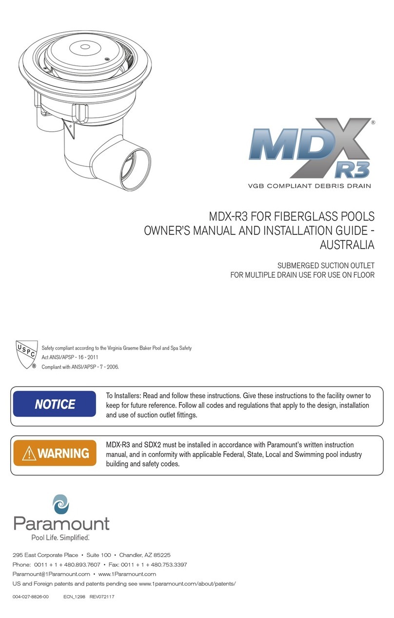
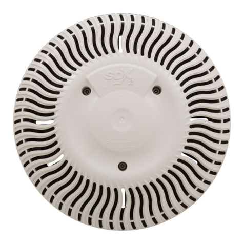
• Elimination of large leaves and debris with Paramount’s patented MDX-R3, VGB Compliant Debris Drain, Debris
Containment Canister, and Paraskim Venturi Powered Skimmer.
BRUSHING IS NOT COMPLETELY ELIMINATED. Although the system GREATLY reduces the time and cost of maintaining a
pool, it DOES NOT ELIMINATE the need to:
• Maintain a proper chemical balance
• Brush the pool periodically
• Clean baskets and filters on a regular basis
In conclusion, the IN-FLOOR SYSTEM is not a 100% cleaner and should never be presented as such.
SURFACE RETURNS
Surface returns used in conjunction with the IN-FLOOR SYSTEM are a builder’s option. If all six ports of the water valve are
not required, the use of surface returns (particularly in areas with excessive surface debris) is highly recommended.
If all six ports of the water valve are utilized for the floor, steps and/or spa, and automatic surface returns are desired, we
recommend a separate pump and filter. Surface returns are also advisable in shallow “game” pools. They would enable people
to use the pool and have the filtration system operating without the possibility of stepping on the cleaning nozzles.
PROPER NOZZLE PLACEMENT
Proper nozzle placement is the single most important item in making the SYSTEM clean properly. As a general rule, one head
is required for each 50 square feet of surface area (in pebble - 40 sq. ft.). Pools with breaks and free form pools will generally
require two (2) additional nozzles. This formula does not include nozzles required for steps and benches. The exact total cannot
be determined until a scaled drawing has been made and nozzles have been properly placed.
NOZZLE PLACEMENT CRITERIA
1. 5’ RADIUS CLEANING IN PLASTER, 4’6” IN PEBBLE
2. DISTANCE FROM VERTICAL SURFACES (WALL OR STEP) MINIMUM 2’ - MAXIMUM 2½’.
3. MAXIMUM DISTANCE FROM CORNER (3 FEET).
4. ALL AREAS MUST INTERSECT OR OVERLAP.
NOTE: SYSTEM MUST USE ONE VENTURI POWERED PARASKIM V SKIMMER AND MDX-R3 DEBRIS
REMOVING DRAIN SYSTEM.
NOTICE Calculations based on a 1’ radius dig in the shallow end and a 5’ radius in the deep end
(assuming maximum depth of 4’ shallow and 9’ deep.)
Table of contents
Other Paramount Fitness Lighting Equipment manuals

Paramount Fitness
Paramount Fitness MDX2 retro User manual

Paramount Fitness
Paramount Fitness MDX2 retro User manual

Paramount Fitness
Paramount Fitness Paraskim V Programming manual

Paramount Fitness
Paramount Fitness MDX-R3 User manual

Paramount Fitness
Paramount Fitness MDX-R3 Programming manual

Paramount Fitness
Paramount Fitness MDX DEBRIS REMOVAL SYSTEM User manual

Paramount Fitness
Paramount Fitness Paraskim V Programming manual

Paramount Fitness
Paramount Fitness PARASCOPE User manual

Paramount Fitness
Paramount Fitness MDX-R3 Programming manual

Paramount Fitness
Paramount Fitness ECO POOL 006-527-6316 Series User manual