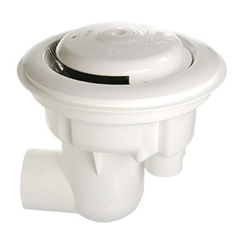
Paramount Fitness MDX-R3 Programming manual

295 East Corporate Place • Suite 100 • Chandler, AZ 85225
Phone: 0011 + 1 + 480.893.7607 • Fax: 0011 + 1 + 480.753.3397
US and Foreign patents and patents pending see www.1paramount.com/about/patents/
004-027-8816-00 REV00 ECN_1298 Plublish 071917
MDX-R3 FOR ADJUSTABLE CONCRETE POOLS
OWNER’S MANUAL AND INSTALLATION GUIDE
- AUSTRALIA
SUBMERGED SUCTION OUTLET
FOR MULTIPLE DRAIN USE FOR USE ON FLOOR
Safety compliant according to the Virginia Graeme Baker Pool and Spa Safety
Act ANSI/APSP - 16 - 2011
Compliant with ANSI/APSP - 7 - 2006.
WARNING MDX-R3 and SDX2 must be installed in accordance with Paramount’s
written instruction manual, and in conformity with applicable Federal,
State, Local and Swimming pool industry building and safety codes.
To Installers: Read and follow these instructions. Give these
instructions to the facility owner to keep for future reference. Follow all
codes and regulations that apply to the design, installation and use of
suction outlet fittings.
NOTICE

For technical assistance call 1.800.621.5886 or contact your regional representative
2
PLEASE REVIEW THE OWNER’S MANUAL AND INSTALLATION GUIDE IN ITS ENTIRETY AND HEED
ALL SAFETY INFORMATION. Failure to follow these instructions and warnings can result in DEATH OR
SERIOUS INJURY.
DANGER indicates
a hazardous
situation which, if
not avoided, will result in death or serious injury.
DANGER
Signal Words and Symbols Used In This Manual
This Owner’s Manual and Installation Guide contains specific precautions and symbols to identify safety-
related information. You will find DANGER, CAUTION, WARNING and NOTICE symbols which require
special attention. Please read them carefully and follow these precautions as indicated! They will explain how to
avoid hazards that may endanger you or persons using or maintaining your pool or spa.
SUCTION ENTRAPMENT HAZARD:
DEATH or SERIOUS INJURY will result if a drain cover or grate is not
installed and used correctly.
• Pool and spa pumps produce high levels of suction and move high volumes of
water, which can cause death or serious injury if a person comes in close proximity to pool or spa drains.
• Keep clear of pool and spa drains to avoid death or serious injury from suction.
DEATH or SERIOUS INJURY will result from pool or spa drain covers or
grates that are improperly installed, missing, clogged, or broken.
• Inspect pool and spa before each use to ensure that drain covers and
grates are properly in place and secured.
• Ensure that drain covers are not damaged, cracked, broken, loose, clogged, not properly secured, or
missing because these conditions increase the chance of death or serious injury from entrapment.
• If a drain cover is discovered damaged, cracked, broken, loose, clogged, not properly secured, or
missing, you should:
• Close the pool or spa immediately; and,
• Post a closure notice and keep the pool or spa closed until an appropriate ANSI/APSP -16-2011
certified drain cover is properly installed.
DANGER DEATH or SERIOUS INJURY will result from hair entanglement or
limb entrapment.
• Keep clear of pool and spa drains.
• Hair sucked into pool or spa drains will tangle and knot trapping the
swimmer underwater. Avoid placing your hair near a pool or spa drain.
• Avoid sitting on pool or spa drains because the suction can cause
severe intestinal damage, evisceration, and/or disembowelment.
DANGER
DANGER
DANGER DEATH or SERIOUS INJURY will result from contact with a damaged,
loose, or missing drain cover.
• Do not allow limbs to contact or be inserted into a drain pipe with a
damaged, loose, or missing drain cover. This could result in swelling of
the limb and/or trapping a swimmer underwater.
• Avoid mechanical entrapment of jewelry, swimsuit, hair decorations,
finger, toe, or knuckle in a drain pipe with damaged, loose, or missing
drain cover. This may result in trapping a swimmer underwater.
• Do not allow body to come into contact with a drain pipe that has a
damaged, loose, or missing drain cover. This may result in trapping a
swimmer underwater.
WARNING indicates
a hazardous situation
which, if not avoided,
could result in death or serious injury.
WARNING
CAUTION indicates
a hazardous situation
which, if not avoided,
could result in minor or moderate injury.
CAUTION NOTICE is used to
address practices
not related to
physical injury.
NOTICE

For technical assistance call 1.800.621.5886 or contact your regional representative
3
MAINTENANCE INSTRUCTIONS & WARNINGS:
DEATH or SERIOUS INJURY can result from pool or spa drain covers or
grates that are clogged by debris.
• All pool and spa drain covers may become obstructed by debris and should be cleaned periodically
due to clogging from debris, such as pieces of plastic, hair, fabric, twigs, leaves, seeds, etc.
• The frequency of periodic cleaning will vary depending on the amount and type of debris introduced
into the pool or spa
• Clogging of the drain cover will increase the suction effect and increase the likelihood of death or
serious injury from those hazards listed above.
• A clogged drain can negatively affect the safety of the drain.
• It is advisable to have a qualified pool or spa professional perform this inspection and debris removal
from the pool an spa drain covers.
• When servicing the drain cover, the pump connected to the suction must be turned off.
• Do not perform any service of the drain cover in water level above your waist.
• Use drain covers only with a pumping system rated for the corresponding flow or less. Failure to do
so can result in hair or body entrapment which can cause death or serious injury. If in doubt about the
rating of your system, consult a qualified pool or spa professional.
• Use only the supplied stainless-steel screws with the drain cover. Screws put into the frame anywhere
except in the original screw holes will not hold and will allow the drain cover to come off the main
drain, causing an entrapment hazard. If a screw hole(s) is stripped, inserts missing, loose, or damaged,
consult your owner’s manual and installation guide for proper steps to replace, correct, or reattach the
compromised drain or drain component.
WARNING Suction can pose a serious hazard to swimmers just as electricity can be a
hazard. Both are important for proper water filtration and both must be treated
with respect. Suction safety begins with a professional design that includes a
quality suction system installed by a certified contractor.
Certified builders will address the following issues when designing and installing a proper filtration system:
• Properly bond-grounded pumps, time clocks, switches and any other metal in or near water. This is required to
address Electrical Shock Hazards.
• Design the suction piping so there are no single-point suction hazards; single-point suction (one drain) is a
leading cause of Body Suction Entrapment Hazards. Note: your certified builder has many effective options for
addressing this hazard; they may include dual-drain systems, like MDX-R3, skimmers, gutters, negative edge
features and many more products and piping designs known to professionals.
• Install ANSI/APSP - 16 - 2011 listed drains, suction covers and debris removal systems. This is the ONLY
approved option for preventing Hair Entrapment Hazards, the leading cause of suction related injuries.
• Design and install an effective circulation system (including optional cleaning systems), to direct filtered water
to all areas and interior surfaces. NOTE: Suction fittings can NOT clean or direct filtered water for proper
sanitation; that can only be done on the pressure (return) side of the filtration system.
While suction injuries are extremely rare, drowning and diving injuries are far too common and there is little
your certified builder can do to eliminate these hazards. You must educate yourself and your guests. Below are
some important safety issues every swimmer must know and recognize.
• PREVENT DROWNING: Watch children at all times, no swimming alone.
• NO DIVING IN SHALLOW WATER: You can be permanently injured.
• PREVENT SUCTION ENTRAPMENT: Inspect suction covers before swimming, keep swimmers away
from suction fittings, protect long hair, don’t swim with loose clothing or large and dangling jewelry.
For more information about the Virginia Graeme Baker Pool and Spa Safety Act, contact the Consumer
Product Safety Commission at (301) 504-7908 or visit www.cpsc.gov.
Always turn off all power to the pool pump before installing the cover
or working on any suction outlet.
WARNING
WARNING

4
The use of two 45˚ in place of a 90˚ allows for the best debris removal
and minimizes large debris from getting caught in the line.
MDX-R3 SYSTEM DESIGN
These MDX-R3 instructions provide two methods to choose from, with additional methods for
specific jurisdictions, (California specifically but not limited to that state). Your local codes may
require additional safety measures. Paramount Pool & Spa Systems and its representatives cannot
recommend or endorse installation methods other than those provided in these MDX-R3 instructions.
Maximum Pump Size:
MDX-R3 is rated for a maximum of 132 GPM (500 LPM). While system
flow rate will vary with pump size and the Total Head Loss for a given
system, virtually any modern pump is capable of exceeding this limit, therefore it is the responsibility of
the system designer to make sure it is not possible to exceed 132 GPM (500 LPM).
NOTICE
In the event of one suction outlet being completely blocked, the remaining suction outlets serving that
system shall have a flow rating capable of the full flow of the pump(s) for the specific suction system.
MDX-R3 and SDX2 must be installed in accordance with Paramount’s
written instruction manual, and in conformity with applicable Federal,
State, Local and Swimming pool industry building and safety codes.
WARNING
NOTICE
NOTICE
Plumbing of the included enlarged suction element (13” of
4” pipe) to the 4" port of the MDX-R3 is required. After the
enlarged suction element, the included reducer adapter may then
be used to reduce the pipe size to 2½”. A 3” coupler may be attached to the outside diameter of
the reducer or a 4” coupler directly to the enlarged suction element for systems where the flow
through the MDX-R3 is intended to exceed 90 GPM. Use of 2½” pipe minimum throughout
the suction side of the system is strongly encouraged for optimum performance. For
your convenience, Paramount Pool & Spa Systems includes the enlarged suction element, and the
reducer adapter with the MDX-R3. To order separately, please see page 12 for the part number.
NOTICE
MDX-R3 VGB COMPLIANT DEBRIS DRAIN
STANDARD POOL DESIGN, AUSTRALIA
DUAL DRAIN
SDX
ENLARGED SUCTION
ELEMENT
50MM OR LARGER
CIRCULATION LINE
SIZE TO MATCH
CIRCULATION LINE
SECOND DRAIN
ANY ORIENTATION
Design Flow Rate = 132 GPM (500 LPM)
Maximum GPM = 132 (500 LPM)
Velocity at 132 GPM = 1.294 FPS (.39 MPS)
For technical assistance call
0011 + 1 + 480.893.7607 or
contact your regional representative.

5
FLOW HEAD LOSS CURVE
MDX-R3 INSTALLATION METHOD 1
*Note: Canister requires 1½” equalizer line through pool wall. (Not Shown)
Compliant with ANSI/APSP - 7 - 2006
WITH CANISTER WITHOUT CANISTER
*Note: Canister requires 1½” equalizer line through pool wall. (Not Shown)
0.00
0.20
0.40
0.60
0.80
1.00
1.20
30
(114)
40
(151)
50
(189)
60
(227)
70
(265)
80
(303)
90
(341)
100
(379)
110
(416)
120
(454)
130
(492)
140
(530)
150
(568)
160
(606)
170
(643)
180
(681)
190
(719)
200
(757)
210
(795)
0.00
0.50
1.00
1.50
2.00
2.50
3.00
FLOW GPM (LPM)
HEAD LOSS (INHG)
HEAD LOSS (CMHG)
SDX
2ND SUCTION OUTLET
MV FUSE IN
CANISTER
50mm
50mm
50mm
ENLARGED SUCTION ELEMENT
TRUNK LINE MUST BE
SIZED TO MEET MAXIMUM
VELOCITY REQUIREMENTS
FOR SUCTION PLUMBING
PER LOCAL CODE
IF NOT USING HYDROSTAT
PLUG 50mm PORT
TO PUMP & SKIMMER
BYPASS
WITH CANISTER AND MV FUSE
MV FUSE
DECK SIDE
50mm
TRUNK LINE MUST BE
SIZED TO MEET MAXIMUM
VELOCITY REQUIREMENTS
FOR SUCTION PLUMBING
PER LOCAL CODE
ENLARGED SUCTION ELEMENT
METHOD 1 WITH DECK CANISTER AND MV FUSE
IF NOT USING HYDROSTAT
PLUG 50mm PORT
50mm
SDX
2ND SUCTION OUTLET
TO PUMP &
SKIMMER BYPASS
50mm
TRUNK LINE MUST BE
SIZED TO MEET MAXIMUM
VELOCITY REQUIREMENTS
FOR SUCTION PLUMBING
PER LOCAL CODE
50mm
ENLARGED SUCTION ELEMENT
WITH CANISTER WITHOUT MV FUSE
IF NOT USING HYDROSTAT
PLUG 50mm PORT
50mm
SDX
2ND SUCTION OUTLET TO PUMP &
SKIMMER BYPASS
TRUNK LINE MUST BE
SIZED TO MEET MAXIMUM
VELOCITY REQUIREMENTS
FOR SUCTION PLUMBING
PER LOCAL CODE
WITHOUT CANISTER AND WITHOUT MV FUSE
50mm
ENLARGED SUCTION ELEMENT
IF NOT USING HYDROSTAT
PLUG 50mm PORT
50mm
SDX
2ND SUCTION OUTLET
TO PUMP &
SKIMMER BYPASS

6
WITH CANISTER WITHOUT CANISTER
MDX-R3 INSTALLATION METHOD 2
TO PUMP
TRUNK LINE MUST BE
SIZED TO MEET MAXIMUM
VELOCITY REQUIREMENTS
FOR SUCTION PLUMBING
PER LOCAL CODE.
65mm OR 90mm
ENLARGED SUCTION ELEMENT
WITH CANISTER AND MV FUSE
IF NOT USING HYDROSTAT
PLUG 2" PORT
MV FUSE IN
CANISTER
IF NOT USING HYDROSTAT
PLUG 2" PORT
65mm OR 90mm
WITH CANISTER WITHOUT MV FUSE
ENLARGED SUCTION ELEMENT
TRUNK LINE MUST BE
SIZED TO MEET MAXIMUM
VELOCITY REQUIREMENTS
FOR SUCTION PLUMBING
PER LOCAL CODE.
TO PUMP
WITH CANISTER WITHOUT CANISTER
TO PUMP
TRUNK LINE MUST BE
SIZED TO MEET MAXIMUM
VELOCITY REQUIREMENTS
FOR SUCTION PLUMBING
PER LOCAL CODE.
65mm OR 90mm
ENLARGED SUCTION ELEMENT
WITH DECK FUSE
IF NOT USING HYDROSTAT
PLUG 2" PORT
MV FUSE DECK SIDE
TO PUMP
TRUNK LINE MUST BE
SIZED TO MEET MAXIMUM
VELOCITY REQUIREMENTS
FOR SUCTION PLUMBING
PER LOCAL CODE.
65mm OR 90mm
WITHOUT CANISTER, WITHOUT MV FUSE
ENLARGED SUCTION ELEMENT
IF NOT USING HYDROSTAT
PLUG 2" PORT
*Note: Canister requires 40mm equalizer line through pool wall. (Not Shown)
ENLARGED SUCTION ELEMENT
IF NOT USING HYDROSTAT
PLUG 2" PORT
SDX
2ND SUCTION OUTLET
2 1/2"
2 1/2"
TO PUMP
TRUNK LINE MUST BE
SIZED TO MEET MAXIMUM
VELOCITY REQUIREMENTS
FOR SUCTION PLUMBING
PER LOCAL CODE.
WITH CANISTER AND MV FUSE
MV FUSE IN
CANISTER
IF NOT USING HYDROSTAT
PLUG 2" PORT
ENLARGED SUCTION ELEMENT
2 1/2"
2 1/2"
TRUNK LINE MUST BE
SIZED TO MEET MAXINUM
VELOCITY REQUIREMENTS
FOR SUCTION PLUMBING
PER LOCAL CODE.
TO PUMP
SDX
2ND SUCTION OUTLET
WITH DECK SIDE MV FUSE
MV FUSE DECK SIDE
SDX
2ND SUCTION OUTLET
2 1/2"
2 1/2"
ENLARGED SUCTION ELEMENT
IF NOT USING HYDROSTAT
PLUG 2" PORT
TRUNK LINE MUST BE
SIZED TO MEET MAXIMUM
VELOCITY REQUIREMENTS
FOR SUCTION PLUMBING
PER LOCAL CODE.
TO PUMP
WITH CANISTER, WITHOUT MV FUSE
TO PUMP
TRUNK LINE MUST BE
SIZED TO MEET MAXIMUM
VELOCITY REQUIREMENTS
FOR SUCTION PLUMBING
PER LOCAL CODE.
SDX
2ND SUCTION OUTLET
2 1/2"
ENLARGED SUCTION ELEMENT
WITHOUT CANISTER, WITHOUT MV FUSE
IF NOT USING HYDROSTAT
PLUG 2" PORT
2 1/2"
*Note: Canister requires 1½” equalizer line through pool wall. (Not Shown)

7
MDX-R3 Plumbing (Fig. 1)
1. Position the top edge of the MDX-R3 sump 1”
below the finished depth of the pool, spa, or a
basin (Fig. 1). Finish concrete to top edge of
construction cap. Orientate the sump so the
elbow is perpendicular to inside wall or end wall
of pool.
2. Position the REQUIRED SDX2 High Flow
Safety Drain® on a sidewall of the pool below
water level (if pool will be winterized, place it
high enough to reach from the deck). Option:
The SDX2 High Flow Safety Drain may be
positioned on the floor a MINIMUM of three (3)
feet away from any other Suction Outlet.
HYDROSTATIC FITTING
The hydrostatic port inside the MDX-R3 Sump
is equivalent to a 2” Threaded Female Adapter
and a 2” Slip Fitting Outside the MDX-R3 Sump.
This port is for the purpose of a hydrostat only.
Paramount recommends the use of the 2” thread
plug provided. Do not use check valves here that
are prone to sticking open causing the need to
open the drain cover exposing a suction risk. If a
hydrostat is not used, plug this port from bottom
with pipe and cap. Do not install any suction
equipment (pump) to this port!
Pressure Test-READ BEFORE
INSTALLATION: New Style Test Plug
The 4” pressure test plugs (005-252-1610-00)
use an o-ring to make the seal.
Wrap once with Teflon tape to prevent plastic
threads from binding. Insert plug into threaded
socket. Use an adjustable wrench, a 1½” 12 pt
socket or pliers on lug and tighten by hand until
snug. Over tightening may cause parts to break.
Pressure should remain on the system through
construction until interior cleanup.
Fig. 2
Fig. 1
MDX-R3 PLUMBING
MDX-R3 PRESSURE TESTING
CONCRETE SHELL
EARTH
FUTURE INTERIOR FINISH
FIGURE 5
2" HYDROSTATIC PLUG
KEY
2 1/2" PORT BLOCKED
OFF IN US VERSION
4" PLUG
Release pressure on
the system before
removing plugs
WARNING

8
The SDX2 High Flow Safety Drain® installed
in a concrete shell utilizes a small cutout in the
concrete to form the sump which is sometimes
made of plastic or fiberglass. This concrete sump
provides superior shell strength by eliminating the
large hole associated with plastic sumps. The
water seal is formed against the suction pipe in the
same way a water tight seal is formed with return
pipes. The concrete cutout is typically 280mm
(11”)wide, by 50mm (2”) deep, with a finger
size cutout around the pipe to allow room for a
watertight seal. (Fig. 3)
Rebar Steel (Fig. 5)
Concrete reinforcing steel should be kept 75mm
away from all pipe and fittings.
Concrete Shell Sump (Fig. 3)
Form a concrete sump around each suction pipe.
Concrete Shell Preparation (Fig. 4)
Prior to installing the interior finish, cut each
SDX2 riser pipe approximately 25mm behind the
concrete shell’s surface.
Fig. 3
Fig. 4
11” (typ)
50mm Deep (typ)
25mm Deep (typ)
SDX2 CONCRETE INSTALLATION
Suction Safety
Standards require
that main drain
grates used to cover concrete sumps, must
have the suction pipe cut at least 1 ½ times
the pipe diameter behind the drain cover. This
is to allow room for even water flow through all
drain cover holes. This is not necessary with
the SDX2 drain because the Patented Design
provides uniform suction regardless of pipe
location. However, if the pipe is too close to
the surface, it may restrict water flow to the
pump, reducing hydraulic efficiency, but this
does not pose a suction safety hazard.
NOTICE
Finger
Size
Cutout

9
Concrete Ring Installation (Fig. 5)
1. Apply interior finishing material.
2. Position the SDX2 Concrete Ring with the
semi-circle tab located at the top and then
press the ring into finishing material.
3. Trowel the finishing material around outside
and inside of the SDX2 Concrete Ring.
4. Form a watertight seal around the suction
pipe.
5. Wipe clean any finishing material that remains
on the SDX2 Concrete Ring’s top edge and
mounting surface.
Concrete Cover Assembly (Fig. 6)
1. Align the SDX2 Concrete Support with the
alignment tab located on the SDX2 Concrete
Ring.
2. Install three (3) machine screws through the
SDX2 Concrete Support. Secure the screws
without over tightening.
3. Align the SDX2 Cover with the SDX2
Support holes.
4. Install three (3) security screws through the
SDX2 cover. Secure the screws without over
tightening.
Fig. 5
75mm Min (typ)
Fig. 6
Keep rebar 75mm away from MDX-R3 sump. (Fig. 7)
1. To allow the sump to be fully encased in concrete, clear dirt to completely expose the sweep elbow.
(Fig. 8)
2. Pack concrete around and under sump (Fig. 8) to ensure seal and strength of shell
3. Angle shell down to MDX-R3 sump. (Fig. 8)
4. Make cut-out around MDX-R3 sump. 440mm round by 19mm deep to water stop down. (Fig. 9 & 11)
Fig. 7
STEEL AND CONCRETE INSTRUCTIONS
82mm
200mm 75mm
TOP OF PIPE
LEVELING RING
TIE WIRE
300mm
150mm
MDX-R3 VGB COMPLIANT DEBRIS DRAIN
STANDARD POOL/SPA/BASIN DESIGN
STEEL CAGE
75mm 75mm
82mm
150mm
150mm
300mm

10
CUTOUT
CUTOUT DEPTH
TO BOTTOM
OF FLANGE
EARTH
CONCRETE SHELL
FUTURE INTERIOR FINISH
FIGURE 6
38 - 50mm
440mm
19mm
Fig. 10
Plaster Ring Installation:
The Concrete Ring should be attached to the MDX-R3 Sump prior to finishing the interior surface of the
pool, spa, or basin.
1. Remove all plugs before starting final finish application. Use an adjustable wrench or pliers to remove 4”
plug. Set the leveling ring at final finish.
2. Align the Leveling Ring Keyway with the Sump Alignment Key. (Fig. 10)
3. Adjust the elevation and the angle of the Leveling Ring to align it with the finished interior surface of the
pool, spa, or basin.
4. Use a sealing compound compatible with the interior surface to lock the Concrete Ring in place and to
provide a water-tight seal.
*Sealing compound example: Topping Mix Cement, hydraulic cement, and Thoro Acryl®60 by ChemRex®
or equivalent.
Assemble the drain PRIOR TO ADDING WATER
1. Remove 4” pressure plug.
2. Install funnel assembly (#3) onto leveling ring (#5) and secure with 4 (four) security screws (#2) with
screw driver security T25 (#15).
3. Install the cover (#1) onto the funnel assembly (#3) and secure with 3 (three) security screws (#2).
Fig. 11
Fig. 8 Fig. 9
CONCRETE SHELL
EARTH
FUTURE INTERIOR FINISH
FIGURE 5
FLAT ALL AROUND
EARTH
CONCRETE SHELL
FUTURE INTERIOR FINISHFUTURE INTERIOR FINISH
FIGURE 7
440mm
LEVELING RING
SEALING COMPOUND
KEY WAY
CUTOUT
FIGURE 8
440mm

11
WITH CANISTER
If vacuum relief suction outlets are located below freeze line skip steps 1 and 2.
1. Remove grate from wall drain and install a 13-¾ blow through plug and blow line to achieve
airlock.
2. If 3rd suction line is installed remove grate, install a 13-¾ blow-through plug and blow line
to achieve airlock.
3. If vent tube is installed, install blow through plug and blow line to achieve airlock. Repeat
vacuum out canister. For winterizing canister visit www.1Paramount.com and click on
winterization instructions.
WITHOUT CANISTER
If vacuum relief suction outlets are located below freeze line skip steps 1 and 2.
1. Remove grate from wall drain and install a 13-¾ blow through plug and blow line to achieve
airlock.
2. If 3rd suction line is installed remove grate, install a 13-¾ blow-through plug and blow line
to achieve airlock.
3. If vent line is installed in main suction line, plug vent line and install blow through plug in
pump inlet and blow line to achieve airlock.
4. Lastly, blow vent line to achieve airlock.
MDX-R3 WINTERIZATION
Vent Tube Warning Labels
Included in each MDX-R3 are two warning labels that need to be
placed on the pool equipment if the pool is to be winterized and has a
vent tube on any of the drains plumbed on the pool. Attach the smaller
label to the vent pipe where it terminates to atmosphere. (See Fig. 9)
Attach the larger label to the control panel next to the controller for the
pump with the vent tube plumbed to it.
(See Fig. 10)
Fig. 9
Fig. 10
WARNING
When starting pool after winterization, remove plug
from atmospheric vent pipe before energizing pool
pump(s)!
Test vent by blocking drain. Air should enter the pipe
and cause the pump to cavitate releasing the suction on
the drain block.
Ave RtIssemeNt
Lors du démarrage de la piscine après l’hiver, retirez le
bouchon du tuyau de ventilation atmosphérique avant
de mettre la pompe (s) de la piscine en marche!
Testez la ventilation en bloquant le drain. L’air doit entrer
dans le tube et provoquer la cavitation de la pompe et
relâcher l’aspiration sur le bloc de drainage.
001-025-8216-00 REV 051314
WARNING
High Suction Atmospheric Vent!
Do not operate pool pump(s) with this pipe plugged!
If necessary to plug vent to winterize the pool do not
restart pool until plug is removed
Ave RtIssemeNt
Ventilation atmosphérique à grande succion!
Ne pas faire fonctionner la pompe (s) de la piscine
avec un bouchon dans ce tuyau!
S’il est nécessaire mettre un bouchon pour hiverner
la piscine, ne pas redémarrer la piscine jusqu’à ce
que le bouchon soit enlevé. 001-025-8215-00 REV 043014

12
Replace cover within 05 installed years
Item Part Number Description
1 005-252-2110-XX Cover (XX = Color Code)
2 005-262-0840-00 Screw Pack (7pcs)
3 005-252-8234-XX Funnel Assembly (Includes Support, Cover, Screws and Adapter)
4 005-252-1045-00 Funnel Adapter
5 005-252-2045-00 Leveling Ring
6 005-262-2028-00 Sump
7 005-252-1605-00 2” Plug NPT (6pcs)
8 005-252-1610-00 4” Plug with O-Ring
9 005-252-5524-00 Enlarged Suction Element
10 005-252-2550-00 Coupler Reducer 4” X 2½”/3”
*11 2” Pipe - Not Included - Cap If Not Used
*12 2” Cap - Not Included - Cap If Not Used
*13 005-262-1153-00 Plaster Cap
14 005-262-1150-00 Sump Construction Cap
15 005-252-0895-00 T25 Security Screwdriver
16 005-525-2097-XX SDX2 High Flow Safety Drain
17 005-252-2066-00 SDX2 Support Concrete
18 005-252-2050-00 SDX2 Ring Concrete
* Not part of MDX-R3
1
2
3
4
5
6
7
8
9
10
11
12
Available Construction Caps
13 14
15
MDX-R3 CONCRETE POOLS PART NUMBERS
16
17
18
For technical assistance call 0011 + 1 + 480.893.7607 or contact your regional representative.
Other manuals for MDX-R3
6
Other Paramount Fitness Lighting Equipment manuals

Paramount Fitness
Paramount Fitness MDX-R3 Programming manual

Paramount Fitness
Paramount Fitness ECOSYSTEM User manual

Paramount Fitness
Paramount Fitness Paraskim V Programming manual

Paramount Fitness
Paramount Fitness MDX DEBRIS REMOVAL SYSTEM User manual

Paramount Fitness
Paramount Fitness MDX-R3 Programming manual

Paramount Fitness
Paramount Fitness Paraskim V Programming manual

Paramount Fitness
Paramount Fitness ECO POOL 006-527-6316 Series User manual

Paramount Fitness
Paramount Fitness MDX-R3 User manual

Paramount Fitness
Paramount Fitness PARASCOPE User manual

Paramount Fitness
Paramount Fitness MDX2 retro User manual