Paramount Fitness MDX2 retro User manual

ANTI-E NTRAP M ENT DE B RI S DRAI NANTI-ENTRAPMENT DEBRIS DRAIN
295 East Corporate Place • Suite 100 • Chandler, AZ 85225
Toll Free: 1.800.621.5886 • Phone: 480.893.7607 • Fax: 480.753.3397
paramount@1Paramount.com • www.1Paramount.com
MDX0805 004-027-8790-00 REV030509
MDX²INSTALLATION MANUAL
VINYL POOLS
S BMERGED S CTION O TLET
FOR M LTIPLE DRAIN SE
FOR SE ON FLOOR
SEE SPECIAL INSTR CTIONS
FOR CALIFORNIA AND
FLORIDA ON PAGES
4 AND 5
Notice to Installers:
Read and follow these instructions. Give these instructions to
the facility owner to keep for future reference. Follow all codes
and regulations that apply to the design, installation and use
of suction outlet fittings.
WARNING: MDX² and SDX must be installed in accordance
with Paramount's written instruction manual, and in conformi-
ty with applicable Federal, State, Local and Swimming pool
industry building and safety codes.
.S. Patent No.: 6,810,537, 7,089,607, 7,178,179
Safety compliant according to the Virginia Graeme Baker
Pool and Spa Safety Act ASME A112.19.8 - 2007

WARNING
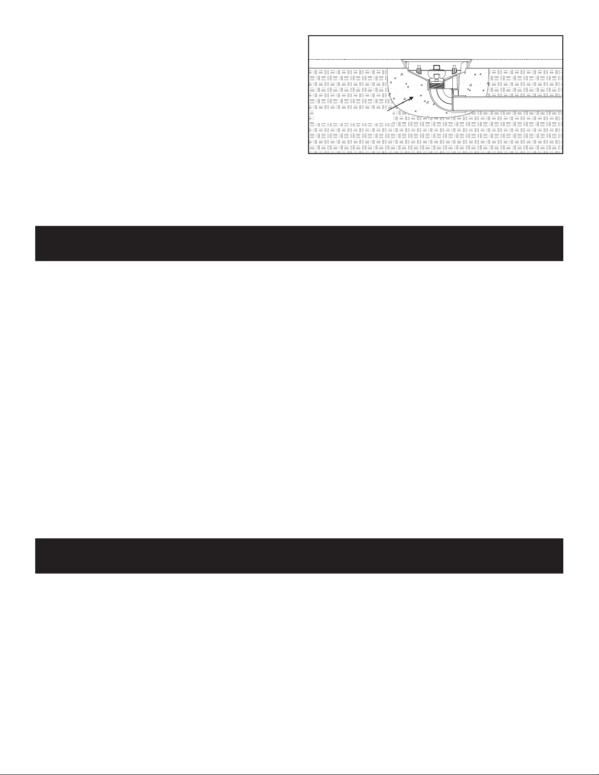
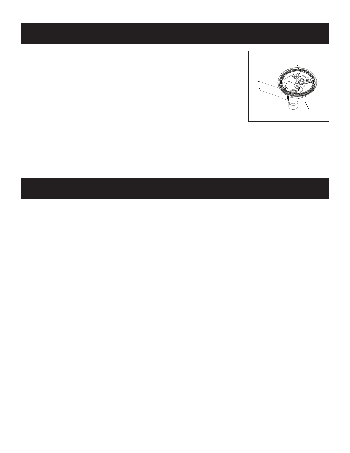
THIS P L MAY HAVE VENT TUBES AS A LAYER F ENTRAPMENT ADV IDANCE N THE SUCTI N UTLETS!
IF A VENT TUBE IS INSTALLED N THIS SYSTEM ATTACH THE ENCL SED WARNING LABELS T THE VENT
PIPE AND C NTR L PANEL AS INSTRUCTED N PAGE 9 F THIS MANUAL. IF THIS P L HAS BEEN
WINTERIZED THE VENT MUST BE INSPECTED WHEN STARTING THE P L F R THE SEAS N. REM VE THE PLUG FR M
THE ATM SPHERIC VENT PIPE BEF RE ENERGIZING THE P L PUMP(S)! TEST THE VENT BY BL CKING THE DRAIN.
AIR SH ULD ENTER THE PIPE AND CAUSE THE PUMP T CAVITATE RELEASING THE SUCTI N N THE DRAIN BL CK.
Suction can pose a serious hazard to swimmers just as electricity can be a hazard. Both are important for proper water
filtration and both must be treated with respect. Suction safety begins with a professional design that includes a quality
suction system installed by a certified contractor.
The MDX² Anti-Entrapment Debris Drain is only available to certified contractors for the same reason certified
electricians are required to connect filtration pumps to public utilities; both require proper training and certification to
assure no hidden hazards are built into the project.
Certified builders will address the following issues when designing and installing a proper filtration system:
• Properly bond-grounded pumps, time clocks, switches and any other metal in or near water. This is required to
address Electrical Shock azards.
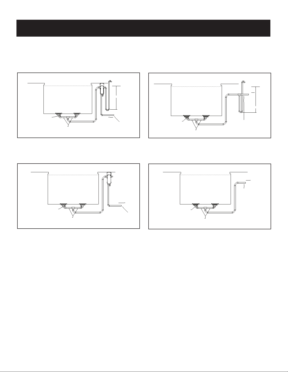
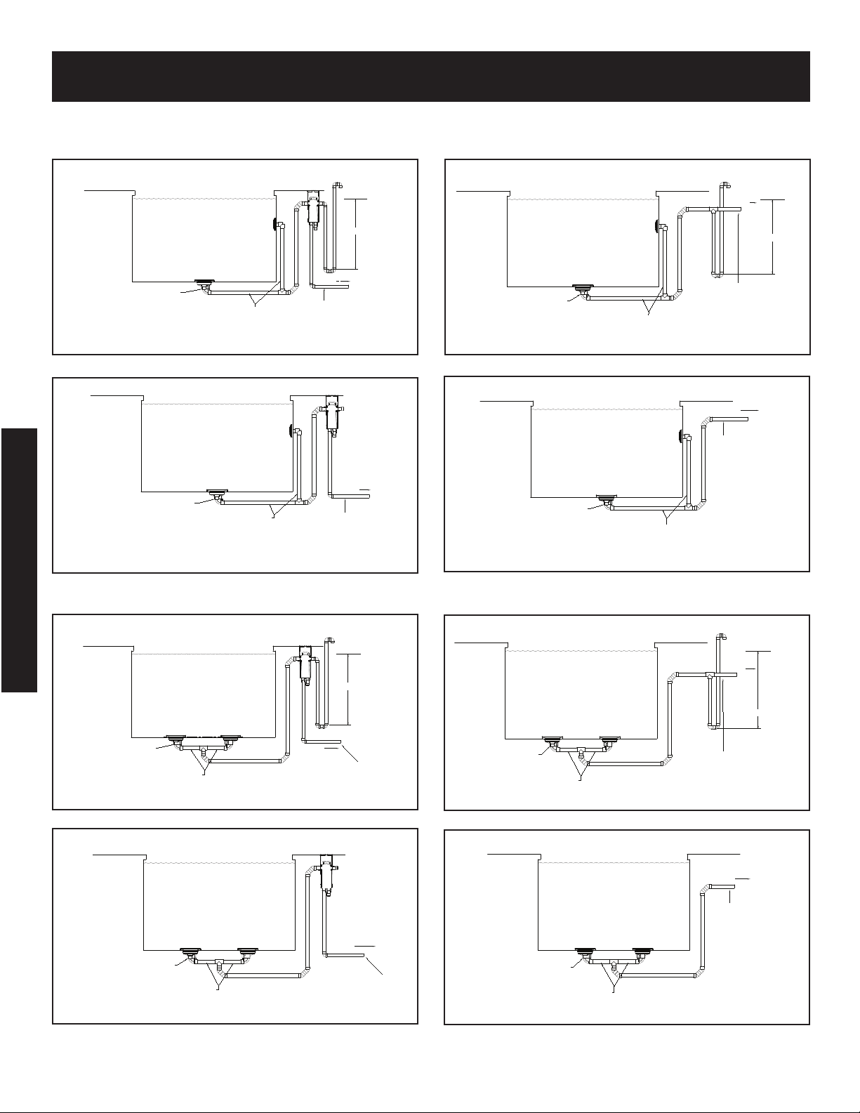
• Design the suction piping so there are no single-point suction hazards; single-point suction (one drain) is a leading
cause of Body Suction Entrapment azards. Note: your certified builder has many effective options for addressing
this hazard; they may include dual-drain systems, like MDX², skimmers, gutters, negative edge features and many
more products and piping designs known to professionals.
• Install ASME A112.19.8 - 2007 listed drains, suction covers and debris removal systems. This is the ONLY
approved option for preventing air Entrapment azards, the leading cause of suction related injuries.
• Design and install an effective circulation system (including optional cleaning systems), to direct filtered water to
all areas and interior surfaces. NOTE: Suction fittings can NOT clean or direct filtered water for proper sanitation;
that can only be done on the pressure (return) side of the filtration system.
While suction injuries are extremely rare, drowning and diving injuries are far too common and there is little your
certified builder can do to eliminate these hazards. You must educate yourself and your guests. Below are some
important safety issues every swimmer must know and recognize.
•PREVENT DROWNING: Watch children at all times, no swimming alone.
•NO DIVING IN S ALLOW WATER: You can be permanently injured.
•PREVENT SUCTION ENTRAPMENT: Inspect suction covers before swimming, keep swimmers away from suction
fittings, protect long hair, don’t swim with loose clothing or large and dangling jewelry.
WARNING: MDX² and SDX must be installed in accordance with Paramount's written instruction manual, and in
conformity with applicable Federal, State, Local and Swimming pool industry building and safety codes.
WARNING
KN WN DR WNING HAZARD.
D N T G NEAR THE SUCTI N FITTINGS R DRAINS F Y UR P L R SPA. Y UR HAIR R B DY
MAY BEC ME TRAPPED CAUSING PERMANENT INJURY R DR WNING.
D N T ENTER THE P L R SPA IF SUCTI N FITTINGS R DRAIN C VERS ARE L SE, BR KEN, R
MISSING. INSPECT SUCTI N FITTING INCLUDING FASTENERS F R DAMAGE N TAMPERING BEF RE
EACH USE F THIS FACILITY.
WARNING
RISK F SEVERE INJURY R DR WNING IF SUCTI N SYSTEMS ARE N T INSTALLED PR PERLY!
N TICE T WNER:
READ, F LL W, AND KEEP THESE SAFETY INSTRUCTI NS F R FUTURE REFERENCE.
IMP RTANT N TICES: PLEASE READ
© 2006, Paramount Pool & Spa Systems
For technical assistance call 1-800-621-5886 or contact your regional representative.

MDX² INSTALLATI N MANUAL
1
System Design:
N TICE:
WARNING: MDX² and SDX must be installed in accordance with Paramount's written instruction manual, and in
conformity with applicable Federal, State, Local and Swimming pool industry building and safety codes.
These MDX² instructions provide two methods to choose from, with additional methods for specific jurisdictions,
(California and Florida specifically but not limited to those states). Your local codes may require additional safety
measures. Paramount Pool & Spa Systems and its representatives cannot recommend or endorse installation
methods other than those provided in these MDX² instructions.
N TICE — Maximum Pump Size:
MDX² is rated for a maximum of 90 GPM (340 LPM). While system flow rate will vary with pump size and the Total
ead Loss for a given system, virtually any modern pump is capable of exceeding this limit, therefore it is the
responsibility of the system designer to make sure it is not possible to exceed 90 GPM (340 LPM). In the event of
one suction outlet being completely blocked, the remaining suction outlets serving that system shall have a flow
rating capable of the full flow of the pump(s) for the specific suction system.
MDX² INSTALLATI N MANUAL
N TICE:
18 inches of 2½" pipe is required to be connected to the center outlet of the MDX² Anti-Entrapment DrainTM. After
the 18 inches of 2½" pipe you may reduce to a smaller pipe size, although it is not recommended. Use of 2½" pipe
throughout the suction side of the system is strongly encouraged for optimum performance. For your convenience,
Paramount Pool & Spa Systems includes the 18 inches of 2½" pipe plus Tee with the MDX² Debris Removal
System. To order separately, please see page 6 for the part number.
SDX
2 1/2" MINIMUM
2 1/2" X 18"
2 1/2" TEE
2" OR LARGER
CIRCULATION LINE
SECOND DRAIN
ANY ORIENTATION
MDX2Anti-Entrapment Debris Drain
STANDARD POOL DESIGN
Dual Drain
Design Flow Rate = 90 GPM
Maximum GPM = 90
Velocity Through Cover
Opening at 90 GPM = 1.368 FPS
For technical assistance call
1-800-621-5886 or contact your
regional representative.

2
MDX² INSTALLATI N
WITH CANISTER WITH UT CANISTER
Installation Method 1:
Flow vs Head Loss
0.00
0.50
1.00
1.50
2.00
2.50
30405060708090100110120130140150
Flow (GPM)
Head Loss (inHg)
FL W HEAD L SS CURVE
METHOD 1 WITH CANISTER, WITH VENT
MDX2
WATERLINE
2"
TO PUMP
2 1/2"
2 1/2"
2 1/2" X 18"
SDX
2ND SUCTION OUTLET
PLUG 2 1/2" SIDE PORT
(IF NOT USING HYDROSTAT,
PLUG 2" PORT)
VACUUM BREAKER
(VENT TO AIR)
5 FT. MIN.
5 1/2 FT. MAX
Trunk line must be sized to
meet maximum velocity
requirements for suction
plumbing per local code.
*Note: Canister requires 1½” equalizer line through pool wall. (Not Shown)
METHOD 1 WITHOUT CANISTER, WITH VENT
2 1/2"
2 1/2" 2"
2 1/2" X 18"
TO PUMP WATERLINE
SDX
2ND SUCTION OUTLET
VACUUM BREAKER
(VENT TO AIR)
5 FT. MIN.
5 1/2 FT. MAX.
PLUG 2 1/2" SIDE PORT
(IF NOT USING HYDROSTAT,
PLUG 2" PORT)
Trunk line must be sized to
meet maximum velocity
requirements for suction
plumbing per local code.
MDX2
METHOD 1 WITH CANISTER, WITHOUT VENT
2 1/2"
TO PUMP
2 1/2"
2 1/2" X 18"
SDX
2ND SUCTION OUTLET
PLUG 2 1/2" SIDE PORT
(IF NOT USING HYDROSTAT,
PLUG 2" PORT)
Trunk line must be sized to
meet maximum velocity
requirements for suction
plumbing per local code.
MDX2
METHOD 1 WITHOUT CANISTER, WITHOUT VENT
TO PUMP
2 1/2"
2 1/2" X 18"
SDX
2ND SUCTION OUTLET
PLUG 2 1/2" SIDE PORT
(IF NOT USING HYDROSTAT,
PLUG 2" PORT)
Trunk line must be sized to
meet maximum velocity
requirements for suction
plumbing per local code.
MDX2
*Note: Canister requires 1½” equalizer line through pool wall. (Not Shown)
For technical assistance call 1-800-621-5886 or contact your regional representative.

MDX² INSTALLATI N
Installation Method 2:
WITH CANISTER WITH UT CANISTER
3
METHOD 2 CA WITH CANISTER, WITH VENT
5 1/2 FT. MAX
5FT. MIN.
WATERLINE
VACUUM BREAKER
(VENT TO AIR)
2"
TO PUMP
2 1/2"
PLUG 2 1/2" SIDE PORT
(IF NOT USING HYDROSTAT,
PLUG 2" PORT)
21/2" X 18"
MDX2MDX2
Trunk line must be sized to
meet maximum velocity
requirements for suction
plumbing per local code.
METHOD 2 CA WITH CANISTER, WITHOUT VENT
2 1/2" X 18" 2 1/2"
PLUG 2 1/2" SIDE PORT
(IF NOT USING HYDROSTAT,
PLUG 2" PORT)
TO PUMP
MDX2MDX2
Trunk line must be sized to
meet maximum velocity
requirements for suction
plumbing per local code.
METHOD 2 CA WITHOUT CANISTER, WITH VENT
51/2 FT. MAX
5 FT. MIN
21/2"
TO PUMP
VACUUM BREAKER
(VENT TO AIR)
PLUG 2 1/2" SIDE PORT
(IF NOT USING HYDROSTAT,
PLUG 2" PORT)
2 1/2" X 18"
WATERLINE
MDX2MDX2
2"
Trunk line must be sized to
meet maximum velocity
requirements for suction
plumbing per local code.
METHOD 2 CA WITHOUT CANISTER, WITHOUT VENT
PLUG 2 1/2" SIDE PORT
(IF NOT USING HYDROSTAT,
PLUG 2" PORT)
2 1/2" X 18"
TO PUMP
MDX2
MDX2
Trunk line must be sized to
meet maximum velocity
requirements for suction
plumbing per local code.
*Note: Canister requires 1½” equalizer line through pool wall. (Not Shown)
For technical assistance call 1-800-621-5886 or contact your regional representative.

4
MDX² CALIF RNIA INSTALLATI N
WITH CANISTER WITH UT CANISTER
METHOD 1 CA WITHOUT CANISTER, WITHOUT VENT
TO PUMP
2 1/2"
PLUG 2 1/2" SIDE PORT
(IF NOT USING HYDROSTAT,
PLUG 2" PORT) EQUAL SIZE AND LENGTH
FROM TEE TO EACH DRAIN
Trunk line must be sized to
meet maximum velocity
requirements for suction
plumbing per local code.
MDX2
METHOD 1 CA WITH CANISTER, WITHOUT VENT
SDX
2ND SUCTION OUTLET
TO PUMP
2 1/2"
PLUG 2 1/2" SIDE PORT
(IF NOT USING HYDROSTAT,
PLUG 2" PORT) EQUAL SIZE AND LENGTH
FROM TEE TO EACH DRAIN
Trunk line must be sized to
meet maximum velocity
requirements for suction
plumbing per local code.
MDX2
METHOD 1 CA WITH CANISTER, WITH VENT
5 1/2 FT. MAX
5 FT. MIN.
SDX
2ND SUCTION OUTLET
WATERLINE
VACUUM BREAKER
(VENT TO AIR)
2"
TO PUMP
2 1/2"
PLUG 2 1/2" SIDE PORT
(IF NOT USING HYDROSTAT,
PLUG 2" PORT) EQUAL SIZE AND LENGTH
FROM TEE TO EACH DRAIN
MDX2
Trunk line must be sized to
meet maximum velocity
requirements for suction
plumbing per local code.
Installation Method 1 (California):
METHOD 1 CA WITHOUT CANISTER, WITH VENT
VACUUM BREAKER
(VENT TO AIR)
5 1/2 FT. MAX.
5 FT. MIN.
2 1/2"
2"
PLUG 2 1/2" SIDE PORT
(IF NOT USING HYDROSTAT,
PLUG 2" PORT)
TO PUMP
SDX
2ND SUCTION OUTLET
WATERLINE
EQUAL SIZE AND LENGTH
FROM TEE TO EACH DRAIN
Trunk line must be sized to
meet maximum velocity
requirements for suction
plumbing per local code.
MDX2
*Note: Canister requires 1½” equalizer line through pool wall. (Not Shown)
METHOD 2 CA WITH CANISTER, WITH VENT
5 1/2 FT. MAX
5 FT. MIN.
WATERLINE
VACUUM BREAKER
(VENT TO AIR)
2"
TO PUMP
2 1/2"
PLUG 2 1/2" SIDE PORT
(IF NOT USING HYDROSTAT,
PLUG 2" PORT)
2 1/2" X 18"
MDX2MDX2
Trunk line must be sized to
meet maximum velocity
requirements for suction
plumbing per local code.
Installation Method 2 (California):
METHOD 2 CA WITH CANISTER, WITHOUT VENT
2 1/2" X 18" 2 1/2"
PLUG 2 1/2" SIDE PORT
(IF NOT USING HYDROSTAT,
PLUG 2" PORT)
TO PUMP
MDX2MDX2
Trunk line must be sized to
meet maximum velocity
requirements for suction
plumbing per local code.
METHOD 2 CA WITHOUT CANISTER, WITH VENT
5 1/2 FT. MAX
5 FT. MIN
2 1/2"
TO PUMP
VACUUM BREAKER
(VENT TO AIR)
PLUG 2 1/2" SIDE PORT
(IF NOT USING HYDROSTAT,
PLUG 2" PORT)
2 1/2" X 18"
WATERLINE
MDX2MDX2
2"
Trunk line must be sized to
meet maximum velocity
requirements for suction
plumbing per local code.
METHOD 2 CA WITHOUT CANISTER, WITHOUT VENT
PLUG 2 1/2" SIDE PORT
(IF NOT USING HYDROSTAT,
PLUG 2" PORT)
2 1/2" X 18"
TO PUMP
MDX2
MDX2
Trunk line must be sized to
meet maximum velocity
requirements for suction
plumbing per local code.
*Note: Canister requires 1½” equalizer line through pool wall. (Not Shown)
For technical assistance call 1-800-621-5886 or contact your regional representative.
CALI F O R N IA

MDX² FL RIDA INSTALLATI N
5
WITH CANISTER WITH UT CANISTER
METHOD FL WITHOUT CANISTER, WITH VENT
2 1/2"
21/2"
21/2" X 18"
TO PUMP
11/2"
SDX
2ND SUCTION OUTLET
PLUG 2 1/2" SIDE PORT
(IF NOT USING HYDROSTAT,
PLUG 2" PORT)
VACUUM BREAKER
(VENT TO AIR)
Trunk line must be sized to
meet maximum velocity
requirements for suction
plumbing per local code.
MDX2
METHOD FL WITH CANISTER, WITH VENT
TO PUMP
2 1/2"
21/2"
21/2" X 18"
11/2"
PLUG 2 1/2" SIDE PORT
(IF NOT USING HYDROSTAT,
PLUG 2" PORT)
SDX
2ND SUCTION OUTLET
VACUUM BREAKER
(VENT TO AIR)
Trunk line must be sized to
meet maximum velocity
requirements for suction
plumbing per local code.
MDX2
Installation Method 1 (Florida):
*Note: Canister requires 1½” equalizer line through pool wall. (Not Shown)
For technical assistance call 1-800-621-5886 or contact your regional representative.
F LO R I DA
N TE: As of March1, 2009 builders in Florida may use Installation Methods 1 and 2 on Page 2 and 3.

MDX² VINYL INSTALLATI N
6
LINER
POOL BASE
CONCRETE FOOTING
MDX² Plumbing (Fig. 1)
1. Position the MDX² Sump even with the finished
depth of the pool, spa or basin (Fig. 1).
Whichever pool base is used, the drain sump must
be encased in concrete as shown to anchor it in
place
2. Position the REQUIRED SDX igh Flow Safety
Drain on a sidewall of the pool below water level (if
pool will be winterized, place it high enough to
reach from the deck). Option: The SDX igh Flow
Safety Drain may be positioned on the floor a
MINIMUM of three (3) feet away from any other
Suction Outlet.
Fig. 1
Pool Base Install
Finish pool base even with upper edge of MDX²
sump (Fig. 1).
Liner Install
1. Make sure bottom gasket is in place before
installing liner.
2. Set liner in pool and draw tight with vacuum.
3. Install top gasket, seal ring and 12 screws.
4. Cut out liner inside of sump. Be sure to trim liner
right up to the inside diameter of seal ring.
Hydrostatic Fitting
The hydrostatic port inside the MDX² Sump is
equivalent to a 2" Threaded Female Adapter and a 2"
Slip Fitting Outside the MDX² Sump. Paramount
recommends the use of the 2” thread plug provided. Do
not use check valves here that are prone to sticking
open causing the need to open the drain cover
exposing a suction risk. This port is for the purpose of a
hydrostat only. If a hydrostat is not used, plug this port
from bottom with pipe and cap. Do not install any
suction equipment (pump) to this port
SDX VINYL INSTALLATI N
1. Select the installation location for the SDX drain. (Additional SDX drains may be used.)
2. For Steel Wall: Make one 4½" hole using a Greenlee®Standard Round Knockout Punch (Greenlee.com - Cat.
No. 742BB / UPC No. 19978)
For Plastic Wall: Cut one 4½" hole using a 4½" hole saw.
For Concrete Wall: Embed one SDX Bulkhead fitting. Protect vinyl liner mounting surface from concrete and
align the back of the flange with the interior surface to allow room for rolled foam around the fitting.
3. Install the SDX Bulkhead Fittings with the “UP” arrow located at the top. (Fig. 2)
a. Discard the Solid Gasket used for fiberglass shells.
b. Mount the SDX Bulkhead Fittings in the wall with the UP arrows at the top.
c. Secure with the SDX Nut. (Not needed for concrete walls.
Assemble the Drain PRI R to adding water:
1. Install lower support (#8) onto sump (#12) with
4 (four) security screws (# 6 and #7) with
screw driver security T25 (#21).
2. Install upper support (#5) onto lower support
(#8) and secure with 8 (eight) security screws
(#4).
3. Install the cover (#3) onto the upper support
(#5) and secure with 6 (six) phillips screws (#2)
and 2 (two) phillips screws (#1).
For technical assistance call 1-800-621-5886 or contact your regional representative.

7
SDX VINYL INSTALLATI N (C NTINUED)
Vinyl Liner
Shell
Notched Gaskets
(Fits One-Way Only)
Fig. 3
Vinyl Cover Assembly (Fig. 3)
1. Prior to installing the Vinyl Liner, apply adhesive to
the non-ribbed side of the two notched gaskets.
2. Align the gaskets with the alignment tabs and
screw holes, then press the gaskets onto the
Bulkhead Fitting and the Bulkhead Support.
3. After installing the Vinyl Liner, align the SDX
Vinyl/Fiberglass Support with the alignment tab
located at the top and bottom of the SDX Bulkhead
Fitting. (Fig. 4)
4. Install five (5) self-tapping screws (Fig. 5)
through the SDX Bulkhead Support with the
T25 Security Screwdriver (Fig. 6). Secure the
screws without over tightening.
5. Cut the Vinyl Liner out of the center of the SDX
Bulkhead Supports to expose the suction piping.
6. Align the SDX Cover with the SDX Support holes.
7. Install three (3) security screws through the SDX
cover. Secure the screws without over tightening.
Fig. 5 Fig. 6
Fig. 4
UP Arrow
Fig. 2
Vinyl Liner
4.Connect the pipe to the secondary outlet of
the MDX².
5.If installing SDX as the vacuum vent in method #2, connect plumbing into tee in the main line as shown in the
diagram on page 4.
For technical assistance call 1-800-621-5886 or contact your regional representative.

8
MDX² VINYL PRESSURE TESTING
Notice: Release pressure on the
system before removing plugs
MDX² VINYL WINTERIZATI N
WITH CANISTER WITH UT CANISTER
If vacuum relief suction outlets are located below freeze
line skip steps 1 and 2.
1. Remove grate from second suction and install a
13-¾ blow through plug and blow line to achieve
airlock.
2. If 3rd suction line is installed remove grate, install a
13-¾ blow-through plug and blow line to achieve
airlock.
3. Go to canister instructions step 1 - 4 below.
4. If vent tube is installed, install blow through plug
and blow line to achieve airlock. Repeat vacuum out
canister. Then complete canister step 5.
If vacuum relief suction outlets are located below freeze
line skip steps 1 and 2.
1. Remove grate from second suction and install a
13-¾ blow through plug and blow line to achieve
airlock.
2. If 3rd suction line is installed remove grate, install a
13-¾ blow-through plug and blow line to achieve
airlock.
3. If vent line is installed in main suction line, plug vent
line and install blow through plug in pump inlet and
blow line to achieve airlock.
4. Lastly, blow vent line to achieve airlock.
Pressure Test-READ BEF RE INSTALLATI N:
New Style Test Plug:
The 2 1/2” pressure test plugs (005-252-1611-00) use an o-ring to make the seal.
Wrap once withTeflon tape to prevent plastic threads from binding. Insert plug into
threaded socket. Set plug wrench on lug and tighten by hand until snug. Over
tightening may cause parts to break. Pressure should remain on the system through
construction until interior cleanup.
2" HYDROSTATIC PLUG
2 1/2" PLUG
For technical assistance call 1-800-621-5886 or contact your regional representative.

9
VENT TUBE WARNING LABELS (Figures 8 and 9)
Included in each MDX² are two warning labels that need
to be placed on the pool equipment if the pool is to be
winterized and has a vent tube on any of the drains
plumbed on the pool. Attach the smaller label to the vent
pipe where it terminates to atmosphere. (See Fig. 8)
Attach the larger label to the control panel next to the
controller for the pump with the vent tube plumbed to it.
(See Fig. 9)
1. Remove outer lid, inner lid and basket, clean and
dry off, and store in same area as modules
2. Install and secure regular winterization plug in
equalizer line of canister to pool at poolside.
3. Install and secure Schrader plug or blow out plug
from canister to main drain. Blow out and obtain air
lock as previously described, if skimmer is tied into
canister, repeat procedure to skimmer.
4. Bottom port of canister to pump may require an
extended pipe for ease of blowing out. Install and
blow out line from canister to pump. Install and
secure plug in pump. Using shop vac, remove all
water from within canister components.
5. Extension pipe can be removed and replaced with
plug or Gizmo type container if Gizmo not used. Be
sure to install device to absorb ice expansion in
canister area. Failure to do this may result in
potential ice freeze damage to canister.
PARAM UNT CANISTER WINTERIZATI N
TEST PLUGS
2" GALV.
SQ. HEAD
BALANCE LINE
TO MAIN
DRAIN
TO OPTIONAL SKIMMER
OR VENT LINE
USE STANDARD
SKIMMER PLUG
WRENCH
Winterization anti-freeze is to be used as necessary or
when required.
Additional questions should be forwarded to
Paramount's corporate office at 800.621.5886.
For technical assistance call 1-800-621-5886 or contact your regional representative.

004-212-2210-XX MDX² ANTI-ENTRAPMENT DRAIN F R VINYL P LS
10
Item Part Number Description
*R1 N/A CAP not used
1 005-252-0872-00 Screw: No. 8X3/8” Security ead (12pk)
2 005-252-0892-00 Screw: No. 8X¾" Security ead (12 pk)
3 005-252-2205-XX MDX Cover (XX=Color Code)
4 005-252-0891-00 Screw: No. 10X¾” Security ead (12pk)
5 005-252-2207-00 Upper Support (XX=Color Code)
6 005-252-0822-00 Screw: No. 10X1 7/8" Security ead (12 pk)
7 005-252-0834-00 Screw: 12 x 2-5/8" Security ead (12 pk)
8 005-252-2209-00 Lower Support
9 005-252-0818-00 Screw: 12-14 x 1 1/2" Vinyl Sump (12 pk)
10 005-252-1605-00 Plug 2" (6 pk)
11 005-252-2044-00 Seal Ring
12 005-252-2014-00 Sump Assembly - 2 1/2"
13 005-252-0010-00 Vinyl Gaskets (2 pk)
14 006-202-6180-00 Sump Adaptor Kit Required to Reduce Pipe Size
15 005-252-1611-00 Plug Pressure Test 2½” w/ O-Ring (4 pcs)
16 004-172-2212-XX SDX igh Flow Safety Drain (2 pk) (XX=Color Code)
17 005-252-0821-00 Screw: 10 X 1 1/4 TORX W/PIN SS B (12 pcs)
18 005-252-2086-XX SDX Cover w/ Screws Vinyl/Fiberglass
19 005-252-0816-00 Screw: 12-14 x 1” B (12 pcs)
20 005-252-2068-00 SDX Support Vinyl/Fiberglass
21 005-252-0072-00 SDX Gasket Vinyl/Fiberglass (2 pk)
22 005-252-2035-00 SDX Bulkhead Vinyl/Fiberglass 2 1/2”/3”
23 005-252-0074-00 SDX Bulkhead Gasket Vinyl/Fiberglass (1 pk)
24 005-252-2090-00 SDX Bulkhead Nut
25* 005-252-0895-00 T25 Security Screwdriver
*N/A 004-252-5476-00 Plug Wrench
* Not Part of MDX²
25
23
16
22
21
20
19
18
17
24
3
5
8
10
11
13
15
R1
9
12
4
2
1
6
7
14
WARNING: MDX² and SDX must be installed in accordance with Paramount's written instruction manual, and in conformity with applicable Federal, State, Local and
Swimming pool industry building and safety codes.
Replace within 05 installed years
Other manuals for MDX2 retro
2
Table of contents
Other Paramount Fitness Lighting Equipment manuals

Paramount Fitness
Paramount Fitness MDX-R3 Programming manual

Paramount Fitness
Paramount Fitness Paraskim V Programming manual

Paramount Fitness
Paramount Fitness MDX DEBRIS REMOVAL SYSTEM User manual

Paramount Fitness
Paramount Fitness SDX 2 User manual

Paramount Fitness
Paramount Fitness MDX2 retro User manual

Paramount Fitness
Paramount Fitness MDX-R3 User manual

Paramount Fitness
Paramount Fitness MDX-R3 Programming manual

Paramount Fitness
Paramount Fitness PARASCOPE User manual

Paramount Fitness
Paramount Fitness MDX-R3 Programming manual

Paramount Fitness
Paramount Fitness ECO POOL 006-527-6316 Series User manual