Paramount Fitness SDX 2 User manual

8175 W. Buckeye Road. Phoenix, AZ 85043
Toll Free: 1.800.621.5886 • Phone: 480.893.7607 • Fax: 480.753.3397
US and Foreign patents and patents pending
see www.1paramount.com/support/patent-numbers/
VGB Compliant ANSI/APSP/ICC-16 2017 LISTED
Certificate of conformity available at
https://www.1paramount.com/downloads/manuals/sdx2/SDX2CertificateOfConformity.pdf
SDX2 and SDX2 Retro must be installed in accordance with
Paramount’s written instruction manual, and in conformity with
applicable Federal, State, Local and Swimming pool industry building
and safety codes. Any modification that increases the flow rate of the circulation system shall
require reevaluation of the cover/grate and sump to ensure that the flow rating of the Suction
Outlet Fitting Assembly (SOFA) is not exceeded.
PROPER INSTALLATION OF THE SDX2 RETRO IS ESSENTIAL.
IF YOU HAVE ANY QUESTIONS, PLEASE CALL PARAMOUNT AT
1.800.621.5886
OR CONTACT YOUR REGIONAL REPRESENTATIVE.
PLEASE FOLLOW ALL LOCAL CODES AND POOL SAFETY GUIDELINES.
When installing and using this equipment, basic safety precautions
shall always be followed, including the following:
IMPORTANT SAFETY INSTRUCTIONS.
To Installers: READ, UNDERSTAND,
AND FOLLOW ALL INSTRUCTIONS
AND WARNINGS.
Give these instructions to the facility owner to keep for future reference. Follow all codes and
regulations that apply to the design, installation and use of suction outlet fittings.
NOTICE
WARNING
DANGER
SAVE THESE INSTRUCTIONS
SUBMERGED SUCTION OUTLET
FOR SINGLE OR MULTIPLE DRAIN USE
FOR USE ON WALL OR FLOOR
OWNER’S MANUAL
MAINTENANCE & INSTALLATION GUIDE
004-027-8745-00 R02 ECN_1941 Publish date 100820 ©2021 Hayward Industries, Inc.

For technical assistance call 1.800.621.5886 or contact your regional representative
2
PLEASE REVIEW THE OWNER’S MANUAL AND INSTALLATION GUIDE IN ITS ENTIRETY AND HEED
ALL SAFETY INFORMATION. Failure to follow these instructions and warnings can result in DEATH OR
SERIOUS INJURY.
DANGER indicates
a hazardous
situation which, if
not avoided, will result in death or serious injury.
DANGER
Signal Words and Symbols Used In This Manual
This Owner’s Manual and Installation Guide contains specific precautions and symbols to identify safety-
related information. You will find DANGER, CAUTION, WARNING and NOTICE symbols which require
special attention. Please read them carefully and follow these precautions as indicated! They will explain how to
avoid hazards that may endanger you or persons using or maintaining your pool or spa.
SUCTION ENTRAPMENT HAZARD:
DEATH or SERIOUS INJURY will result from pool or spa drain covers or
grates that are improperly installed, missing, clogged, or broken.
• Inspect pool and spa before each use to ensure that drain covers and
grates are properly in place and secured.
• Ensure that drain covers are not damaged, cracked, broken, loose, clogged, not properly
secured, or missing because these conditions increase the chance of death or serious injury from
entrapment.
• If a drain cover is discovered damaged, cracked, broken, loose, clogged, not properly secured, or
missing, you shall:
• Close the pool or spa immediately; and,
• Post a closure notice and keep the pool or spa closed until an appropriate ANSI/APSP/ICC-16
2017 certified drain cover is properly installed.
• Missing, broken, or cracked SOFA component shall be replaced before bathers are allowed to use the pool.
• Loose cover/grates shall be reattached before bathers are allowed to use the pool.
DANGER
DANGER DEATH or SERIOUS INJURY will result from hair entanglement or
limb entrapment.
• Keep clear of pool and spa drains.
• Hair sucked into pool or spa drains will tangle and knot trapping the
swimmer underwater. Avoid placing your hair near a pool or spa drain.
• Avoid sitting on pool or spa drains because the suction can cause
severe intestinal damage, evisceration, and/or disembowelment.
WARNING indicates
a hazardous situation
which, if not avoided,
could result in death or serious injury.
WARNING
CAUTION indicates
a hazardous situation
which, if not avoided,
could result in minor or moderate injury.
CAUTION NOTICE is used to
address practices
not related to
physical injury.
NOTICE
• DEATH or SERIOUS INJURY will result if a drain cover or grate is
not installed and used correctly.
• Pool and spa pumps produce high levels of suction and move high volumes
of water, which can cause death or serious injury if a person comes in close proximity to pool or spa drains.
• SOFA shall not be located on seats or the back rests for seats
• Any modification that increases the flow rate of the circulation system shall require reevaluation of the cover/
grate and sump to ensure that the flow rating of the Suction Outlet Fitting Assembly (SOFA) is not exceeded.
• Keep clear of pool and spa drains to avoid death or serious injury from suction.
DANGER

For technical assistance call 1.800.621.5886 or contact your regional representative
3
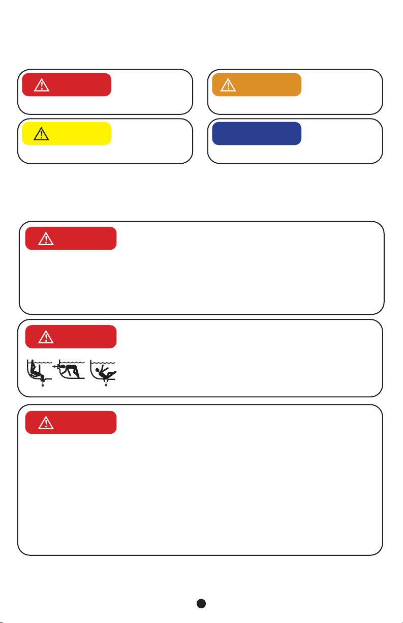
DANGER DEATH or SERIOUS INJURY will result from contact with a
damaged, loose, or missing drain cover.
• Do not allow limbs to contact or be inserted into a drain pipe with a
damaged, loose, or missing drain cover. This could result in swelling of
the limb and/or trapping a swimmer underwater.
• Avoid mechanical entrapment of jewelry, swimsuit, hair decorations,
finger, toe, or knuckle in a drain pipe with damaged, loose, or missing
drain cover. This may result in trapping a swimmer underwater.
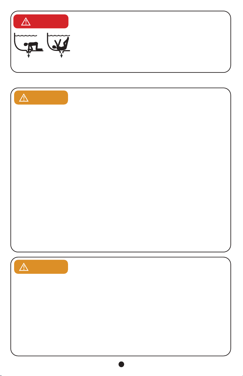
• Do not allow body to come into contact with a drain pipe that has a damaged, loose, or missing
drain cover. This may result in trapping a swimmer underwater.
MAINTENANCE INSTRUCTIONS & WARNINGS:
WARNING DEATH or SERIOUS INJURY can result from pool or spa drain covers
or grates that are clogged by debris.
• Any field modification made to a SOFA not authorized by the
manufacturer’s instructions shall void the SOFA certification.
• No modification shall be made to the SOFA structure or flow path unless the new configuration has
been certified as a new SOFA.
• All pool and spa drain covers may become obstructed by debris and should be cleaned periodically
due to clogging from debris, such as pieces of plastic, hair, fabric, twigs, leaves, seeds, etc.
• The frequency of periodic cleaning will vary depending on the amount and type of debris introduced
into the pool or spa.
• Clogging of the drain cover will increase the suction effect and increase the likelihood of death or
serious injury from those hazards listed above.
• A clogged drain can negatively affect the safety of the drain.
• It is advisable to have a qualified pool or spa professional perform this inspection and debris removal
from the pool an spa drain covers.
• When servicing the drain cover, the pump connected to the suction must be turned off.
• Do not perform any service of the drain cover in water level above your waist.
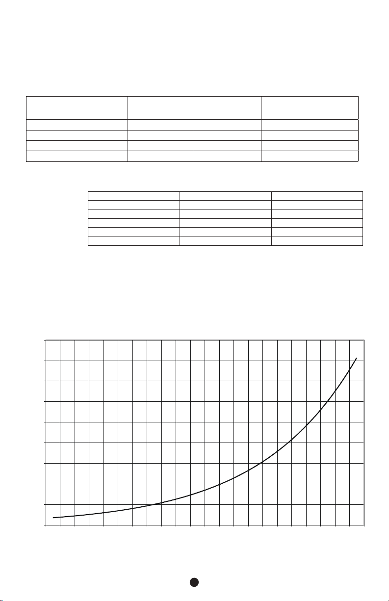
• Use drain covers only with a pumping system rated for the corresponding flow or less. Failure to do
so can result in hair or body entrapment which can cause death or serious injury. If in doubt about
the rating of your system, consult a qualified pool or spa professional.
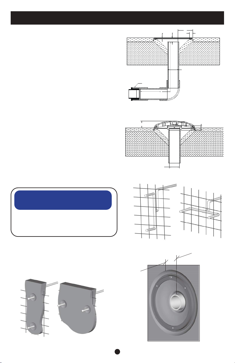
• Use only the supplied stainless-steel screws with the drain cover. Screws put into the frame
anywhere except in the original screw holes will not hold and will allow the drain cover to come off
the main drain, causing an entrapment hazard. If a screw hole(s) is stripped, inserts missing, loose,
or damaged, consult your owner’s manual and installation guide for proper steps to replace, correct,
or reattach the compromised drain or drain component.
• The use of adhesives or other attachment methods that prevent access to suction piping or SOFA
components requiring periodic service is prohibited.
WARNING Suction can pose a serious hazard to swimmers just as electricity can be a
hazard. Both are important for proper water filtration and both must be treated
with respect. Suction safety begins with a professional design that includes a
quality suction system installed by a certified contractor.
Certified builders will address the following issues when designing and installing a proper filtration system:
• Properly bond-grounded pumps, time clocks, switches and any other metal in or near water. This is required to
address Electrical Shock Hazards.
• Design the suction piping so there are no single-point suction hazards; single-point suction (one drain) is a
leading cause of Body Suction Entrapment Hazards. Note: your certified builder has many effective options for
addressing this hazard; they may include dual-drain systems, like MDX-R3, skimmers, gutters, negative edge
features and many more products and piping designs known to professionals.
• Install ANSI/APSP/ICC-16 2017 listed drains, suction covers and debris removal systems. This is the ONLY
approved option for preventing Hair Entrapment Hazards, the leading cause of suction related injuries.
• Design and install an effective circulation system (including optional cleaning systems), to direct filtered water
to all areas and interior surfaces. NOTE: Suction fittings can NOT clean or direct filtered water for proper
sanitation; that can only be done on the pressure (return) side of the filtration system.

For technical assistance call 1.800.621.5886 or contact your regional representative
4
While suction injuries are extremely rare, drowning and diving injuries are far too common and there is little your
certified builder can do to eliminate these hazards. You must educate yourself and your guests. Below are some
important safety issues every swimmer must know and recognize.
• PREVENT DROWNING: Watch children at all times, no swimming alone.
• NO DIVING IN SHALLOW WATER: You can be permanently injured.
• PREVENT SUCTION ENTRAPMENT: Inspect suction covers before swimming, keep swimmers away from
suction fittings, protect long hair, don’t swim with loose clothing or large and dangling jewelry.
For more information about the Virginia Graeme Baker Pool and Spa Safety Act, contact the Consumer
Product Safety Commission at (301) 504-7908 or visit www.cpsc.gov.
Always turn off all power to the pool pump before installing the cover
or working on any suction outlet.
WARNING
• Cover/Grates and all other SOFA components shall be replaced at or before the end of their service
life. Service life begins the month and year in which the SOFA is installed with or without water. See
parts breakdown at end of this manual for specific component service life notations.
• Any SOFA component that is severely faded, chalking, or brittle when flexed shall be replaced even if it
has not reached its indicated service life.
• If the sump/mud ring or any screw receptacle is stripped, cracked or broken that component must be
replaced.
• Any SOFA component held in place by the pool finish or concrete substrate that becomes cracked
or broken; the material that holds it must be stripped from around the SOFA and new components
“mudded” in place. The surface substrate must be free of deterioration and voids.
ADHERE REPLACE COVER ASSEMBLY
STICKER TO THIS PAGE
SAMPLE
Replace cover assembly within (5) five years.
Replace all other components within (25) years.
SDX2 pool wall & floor drain cover part #005-252-2097-XX
Maximum GPM = See install manual for complete chart
Circle year and month of installation.
001-025-8822-00 ECN 1996 REV01 PUB 012821
©2021 Hayward Industries, Inc.
8175 W. Buckeye Rd., Phoenix, AZ 85043
1-800-621-5886 • 1paramount.com
Adhere this label to page 4 of the installation manual.
Must mark year and month of installation
Year 2021 2022 2023 2024 2025
Month 01 02 03 04 05 06 07 08 09 10 11 12
System flow rate ____________________________________
Installed location ____________________________________

For technical assistance call 1.800.621.5886 or contact your regional representative
5
HOW SDX2 WORKS BETTER
The SDX2 high flow drain system is a dual-drain system designed and tested to safely deliver water to modern
high flow pumps.
Each Drain Addresses All Entrapment Hazards
Hair Entrapment Avoidance. At the heart of the patented design is a cover that acts much like sixty
self-regulating drains. This is significant because as some of the ‘little’ drains are covered, excessive suction
does not transfer to the remaining openings. When excessive suction is transferred to unblocked openings
in a traditional drain grate, the suction causes hair to enter multiple openings, creating a potential entrapment
hazard if the hair tangles or puffs up inside the drain, making it impossible to pull free.
Body Entrapment Avoidance. The same self-regulating openings that protect against hair entrapment
hazards, also provides body entrapment protection. When the self-regulating openings built into the SDX2
cover are combined with it’s domed, anti-vortex shape, forming a seal with the cover is difficult.
Security. The SDX2 cover is held firmly in place with three recessed security screws which are made from
top quality 316 Stainless Steel. And behind the SDX2 cover are at least three more screws to hold the whole
assembly in place, providing multiple layers of anti-entrapment protection.
Durability. The SDX2 cover and support materials are far more durable than ABS, the typical plastic used
in swimming pool drain covers. In addition to fading, the Buna in ABS is prone to UV degradation resulting in
structural failures which contribute significantly to suction entrapment hazards.
Dual-Drain System
Vacuum Breaker Backup. As with any dual-drain system, one drain is intended to be a vacuum breaker for
the other in the unlikely event a swimmer completely blocks one of the SDX2 drains. In the event of one suction
outlet is being completely blocked, the remaining suction outlets is capable of the full flow of the pump(s).
Dual-Drain Spacing. Most suction safety codes require dual-drains to be installed three feet apart, pipe
to pipe, however some codes require three feet between drain covers. For this reason, Dual SDX2 piping is
spaced three (3) feet, ten (10) inches apart. If the drains are located closer than 3 feet, the drains must be
located on two different planes (i.e. one on the bottom and one on the vertical wall, or one each on to separate
vertical walls), to make it unlikely both drains could be blocked simultaneously.
Vertical Dual-Drain Installation. The purpose of the vertical dual-drain installation is to make it less likely
two people can approach two drains at once. Effectively, the second drain would be at an individual’s feet.
SDX2 HIGH FLOW SAFETY DRAIN SYSTEM DESIGN
DANGER Check the SDX2 drain cover, fittings and fasteners for damage or
tampering before installation and use.
SDX2 is a circulation drain, not intended to remove debris. For this reason it is suggested SDX2 be installed on
walls whenever possible. SDX2 is a high flow safety drain system submerged suction outlet suitable for single
or multiple drain use on the wall and floor. This is to keep debris and sand from collecting on and around the low
velocity SDX2 cover. Do not locate suction outlets on seating areas or on the backrest of such seating areas.
Drain covers
deteriorate over time
due to exposure to
sunlight and pool chemicals and must be replaced
every five (5) years from installation (or earlier if the
cover or grate becomes damaged in any way).
CAUTION Some covers
and grates are
incompatible with
other manufacturers’ frames and the existing
frame must first be removed and a new supplied
frame installed.
NOTICE

For technical assistance call 1.800.621.5886 or contact your regional representative
6
The maximum flow rate for each pair of SDX2 drains varies depending on size
and orientation of pipe and location on wall or floor. See chart below for flow
limits based on variables. Any modification that increases the flow rate of the
circulation system shall require reevaluation of the cover/grate and sump to ensure that the flow rating of
the Suction Outlet Fitting Assembly (SOFA) is not exceeded. Compliance with this standard requires that
these SOFA-configuration specific flow ratings NOT be exceeded at any time the pool is open to bathers.
Compliance with this standard requires selecting and installing a SOFA, or combination of SOFAs, such
that the resulting individual suction system flow rating is greater than the pumping system’s maximum
system flow rate.
WARNING
The velocity at the opening to the SDX2 drain at the system flow is equal to gpm/134.648=(X)FPS. For
multiple drain systems where more than two drains are used, the maximum flow rate is calculated per ANSI/
APSP-7 Section 4.6 as shown in the following chart.
SOFA SDX2 FLOW RATINGS
Flow Rating (GPM) Pipe Size Pipe Port Orientation Drain Mounting Orientation
180 3" Side Floor
116 2.5" Side Floor
100 2" Side Floor
60 1.5" Side Floor
178 3" Bottom Floor
120 2.5" Bottom Floor
100 2" Bottom Floor
60 1.5" Bottom Floor
140 3" Side Wall
108 2.5" Side Wall
100 2" Side Wall
60 1.5" Side Wall
140 3" Bottom Wall
108 2.5" Bottom Wall
100 2" Bottom Wall
60 1.5" Bottom Wall

For technical assistance call 1.800.621.5886 or contact your regional representative
7
Pipe size. To
design an efficient
suction system in
accordance with
national swimming
pool standards,
the following pipe
sizing guideline
should be followed:
DESCRIPTION MAXIMUM SYSTEM
FLOW FLOOR MAXIMUM SYSTEM
FLOW WALL
MINIMUM FLOW RATING OF
EACH COVER %
MAXIMUM SYSTEM FLOW RATE
*One SDX2 High Flow Safety Drain 180 gpm (681 lpm) 140 gpm (529 lpm) 100%
Two SDX2 High Flow Safety Drains 180 gpm (681 lpm) 140 gpm (529 lpm) 100%
Three SDX2 High Flow Safety Drains 360 gpm (1362 lpm) 210 gpm (795 lpm) 66.7%
Four SDX2 High Flow Safety Drains 360 gpm (1362 lpm) 280 gpm (1060 lpm) 50%
*The addition of an approved SVRS is required when a single SDX2 is being used.
Table derived from ANSI/APSP-7 Section 4.6 Table 1. System flow based on 3"side outlet floor plumbing configuration chart on
page 6.
SUCTION PIPE SIZE MAX RESIDENTIAL GPM MAX PUBLIC GPM
1½” 50 37
2” 82 62
2½” 117 88
3” 181 136
4” 313 (180 Max gpm) 234 (180 Max gpm)
*minimum pipe size 1½"
The flow rating for pools with multiple, blockable SOFAs piped together in one body of water without isolation
valves shall be determined by combining the flow rating of all SOFAs, minus the flow rating of one. If the flow
ratings of all SOFAs are not equal, subtract the flow rating of the SOFA with the highest flow rating.
The flow rating for existing pools with a single, blockable SOFA is the flow rating of the SOFA, when also
installed in conjunction with an additional device or system designed to prevent suction entrapment, where the
additional device or systems is of a type listed in section 9.4. A single, blockable SOFA in a system that does
not also include one of the additional devices or systems shall result in a flow rating of zero.
HEAD LOSS CURVE SDX2
Flow vs Head Loss
0.00
1.00
2.00
3.00
4.00
5.00
6.00
7.00
8.00
9.00
40 50 60 70 80 90 100 110 120 130 140 150 160 170 180 190 200 210 220 230 240 250
Flow (GPM)
Head Loss (inHg)

For technical assistance call 1.800.621.5886 or contact your regional representative
8
SDX2 installed in a concrete shell utilizes a small cutout
in the concrete to form the sump which is sometimes
made of plastic or fiberglass. This concrete sump
provides superior shell strength by eliminating the large
hole associated with plastic sumps. The water seal is
formed against the suction pipe in the same way a water
tight seal is formed with return pipes. Minimal sump
specifications are shown in “Fig. 1a”. The typical water
flow path is shown in “Fig. 1b”
Concrete Plumbing “Fig. 2”
1. Select the installation location for the dual SDX2 drains.
2. Choose the dual-drain orientation, vertical (preferred)
or horizontal.
3. Fabricate the dual-drain pipe tree prior to installation.
4. Position at the desired depth before connecting to
pump suction pipe.
Rebar Steel
Concrete reinforcing steel should be kept 3” away from
all pipe and fittings.
Concrete Shell Sump
Form a concrete sump around each suction pipe. “Fig. 3”
3’10”
Fig. 2
3’10”
Fig. 3
NOTICE
The pipe size must be appropriate for the
maximum anticipated system flow rate per chart
on page 6. Refer to the table on page 7
for pipe sizes and orientations.
CONCRETE INSTALLATION
Concrete Shell Preparation “Fig. 4”
Prior to installing the interior finish, cut each SDX2 riser
pipe a minimum 1” behind the concrete shell’s surface. 1” Deep (typ)
Fig. 4
Fig. 1a
A
2.5
.8
1.0
.3
Specified PVC pipe size per table on page 6.
A.
Minimum Sump Depth = 1.0B.
Minimum Ledge Depth = .3C.
Maximum Ledge Depth = .8D.
Minimum Pipe Offset = 2.5E.
Minimum Length Before Reduction = 16"
F.
F
F
Pipe Size Reduction
1.1Less Than 2 Inches
Suction
Pipe
Opening
Fig. 1b

For technical assistance call 1.800.621.5886 or contact your regional representative
9
Concrete Ring Installation “Fig. 5”
1. Apply interior finishing material.
2. Position the SDX2 Concrete Ring with the semi-
circle tab located at the top and then press the
ring flush into finishing material.
3. Trowel the finishing material around outside and
inside of the SDX2 Concrete Ring.
4. Form a watertight seal around the suction pipe.
5. Wipe clean any finishing material that remains on
the SDX2 Concrete Ring’s top edge and mounting
surface.
Concrete Cover Assembly “Fig. 6”
1. Align the SDX2 Concrete Support with the
alignment tab located on the SDX2 Concrete
Ring.
2. SOFA components and fastener receptacles
shall be clean and free of debris and obstruction
during installation of cover/grate fasteners.
3. Install three (3) machine screws through the
SDX2 Concrete Support. Secure the screws
without over tightening to 18 in-lbs.
4. Align the SDX2 Cover with the SDX2 Support
holes.
5. Install three (3) security screws through the
SDX2 cover. Secure screws to (14 in-lbs)
6. After securing each SOFA component hand
check that it is snug to the sump /frame before
proceeding to the next component.
3” Min (typ)
Fig. 5
Fig. 6
NOTICE
The concrete ring must be mounted flush as the
entire drain assembly must be less than 2"tall
“Fig. 1b”.

For technical assistance call 1.800.621.5886 or contact your regional representative
10
1. Select the installation location for the dual SDX2 drains. (Additional SDX2 drains may be used.)
2. Choose the dual-drain orientation, vertical or horizontal. “Fig. 2” pg. 8
3. For Steel Wall: Make two 4 ½” holes 46” apart using a Greenlee® Standard Round Knockout Punch
(Greenlee.com - Cat. No. 742BB / UPC No. 19978)
For Plastic Wall:
Cut two 4 ½” holes 46” apart using a 4 ½” hole saw.
For Concrete Wall:
Embed two SDX2 Bulkhead fittings 46” apart. Protect vinyl
liner mounting surface from concrete and align the back of the
flange with the interior surface to allow room for rolled foam
around the fitting.
1. Install the SDX2 Bulkhead Fittings with the “UP” arrow
located at the top. “Fig. 7”
a. Discard the solid gasket used for fiberglass shells.
b. Mount the SDX2 bulkhead fittings in the wall with
the UP arrows at the top.
c. Secure with the SDX2 nut. (Not needed for
concrete walls.
2. Connect the suction piping. “Fig. 8”
DO NOT USE
POWER TOOLS
TO INSTALL
FASTENERS. Start all fasteners by hand to prevent
cross threading.
NOTICE
Vinyl Cover Assembly “Fig. 9”
1. Prior to installing the Vinyl Liner, apply adhesive to the
non-ribbed side of the two notched gaskets.
2. Align the gaskets with the alignment tabs and screw
holes, then press the gaskets onto the Bulkhead Fitting
and the Bulkhead Support.
3. SOFA components and fastener receptacles shall
be clean and free of debris and obstruction during
installation of cover/grate fasteners.
4. After installing the Vinyl Liner, align the SDX2 Vinyl/
Fiberglass Support with the alignment tab located at the
top of the SDX2 Bulkhead Fitting. “Fig. 10”
5. Install five(5) self-tapping screws “Fig. 11” through the
SDX2 Bulkhead Support with the T25 Security Screw Driver “Fig. 12”. Secure all screws to 22 in-lbs.
6. After securing each SOFA component hand check that it is snug to the sump /frame before
proceeding to the next component.
7. Cut the Vinyl Liner out of the center of the SDX2 Bulkhead Supports to expose the suction piping.
8. Align the SDX2 Cover with the SDX2 Support holes.
9. Install three(3) security screws through the SDX2 cover. Secure all screws to 6 in-lbs.
VINYL INSTALLATION
Fig. 8
Fig. 7
Vinyl Liner
UP Arrow
Vinyl Liner
Shell
Notched Gaskets
(Fits One-Way Only)
Fig. 9
Fig. 10 Fig. 11 Fig. 12

For technical assistance call 1.800.621.5886 or contact your regional representative
11
1. Select the installation location for the dual SDX2 drains. (Additional SDX2 drains may be used.)
2. Choose the dual-drain orientation, vertical or horizontal. “Fig. 2” pg. 8
3. For Fiberglass Wall: Cut two 4 ½” holes 46” apart using a 4 ½” hole saw.
4. Install the SDX2 Bulkhead Fittings with the “UP” arrow located at the top.
For Fiberglass Shells: “Fig. 13”
a. Place the solid Gasket with the smooth side against
the Bulkhead Fitting flange. (Silicone adhesive may
be substituted for the Gasket if preferred.)
b. Mount the SDX2 Bulkhead Fittings in the hole with
the UP arrow at the top of each fitting.
c. Secure with the SDX2 Nut.
5. Connect the suction piping. “Fig. 14”
DO NOT USE
POWER TOOLS
TO INSTALL
FASTENERS. Start all fasteners by hand to prevent
cross threading.
NOTICE
Fiberglass Cover Assembly “Fig. 15”
1. Prior to installing the support, apply adhesive to the
non-ribbed side of the two notched gaskets.
2. Align the gaskets with the alignment tabs and screw
holes, then press the gaskets onto the Bulkhead Fitting
and the Bulkhead Support.
3. SOFA components and fastener receptacles shall
be clean and free of debris and obstruction during
installation of cover/grate fasteners.
4. Align the SDX2 Vinyl/Fiberglass support with the
alignment tab located at the top of the SDX2 Bulkhead
Fitting. “Fig. 16”
5. Install five (5) self-tapping screws “Fig. 17”through the
SDX2 Bulkhead Support with the T25 Security Screw
Driver “Fig. 18”. Secure all screws to 22 in-lbs.
6. After securing each SOFA component hand check
that it is snug to the sump /frame before proceeding
to the next component.
7. Align the SDX2 Cover with the SDX2 Support holes.
8. Install three(3) security screws through the SDX2
cover. Secure all screws to 6 in-lbs.
FIBERGLASS INSTALLATION
Fig. 13
UP Arrow
Solid Gasket
Fiberglass Shell
Fig. 14
Fiberglass
Shell
Solid
Gasket
Fig. 15
Fig. 16 Fig. 17 Fig. 18

For technical assistance call 1.800.621.5886 or contact your regional representative
12
Vertical Installation
1. Remove grate from upper SDX2 and install blow
through plug and blow line until air comes from
lower grate.
2. Install blow through plug in pump and blow line to
achieve airlock to lower SDX2.
Horizontal Installation
1. Install blow through plug in pump and blow line to
achieve airlock to SDX2.
This may not be the only means to winterize and may
not be the best option in all environments. It is up to the
service professional to provide adequate winterization.
Winterization anti-freeze is to be used as necessary
or when required.
SDX2 WINTERIZATION PROCEDURE
**Replace cover within 05 installed years. ***Replace all other
components within 25 installed years
Item Part Number Description
1** 005-252-2097-XX SDX2 Cover w/ Screws Concrete
2*** 005-252-2066-00 SDX2 Support Concrete
3*** 005-252-2050-00 SDX2 Ring Concrete
4** 005-252-0810-00 SDX2 Screw Pack Complete
5* 005-252-0895-00 T25 Security Screwdriver
XX = Color Code
* Not Part of SDX2
PROPER INSTALLATION OF THE SDX2 IS ESSENTIAL. PLEASE FOLLOW ALL LOCAL CODES AND POOL SAFETY
GUIDELINES.
SDX2 and SDX2 Retro must be installed in accordance with Paramount’s
written instruction manual and in conformity with applicable Federal, State,
Local and Swimming pool industry building and safety codes.
NOTICE
SDX2 CONCRETE PART NUMBERS
1
2
3
5
4

For technical assistance call 1.800.621.5886 or contact your regional representative
13
Item Part Number Description
1** 005-252-2098-XX SDX2 Cover w/ Screws Vinyl/Fiberglass
2*** 005-252-2061-00 SDX2 Support Vinyl/Fiberglass
3*** 005-252-0072-00 SDX2 Gasket Set Vinyl/Fiberglass
4*** 005-252-2035-00 SDX2 Bulkhead Vinyl/Fiberglass 2 1/2”/3”
5*** 005-252-2090-00 SDX2 Bulkhead Nut
6** 005-252-0811-00 SDX2 Screw Pack Complete for Vinyl & Fiberglass
7* 005-252-0895-00 T25 Security Screwdriver
XX = Color Code
* Not Part of SDX2
SDX2 VINYL/FIBERGLASS PART NUMBERS
PROPER INSTALLATION OF THE SDX2 IS ESSENTIAL. PLEASE FOLLOW ALL LOCAL CODES AND POOL SAFETY
GUIDELINES.
SDX2 and SDX2 Retro must be installed in accordance with
Paramount’s written instruction manual and in conformity with
applicable Federal, State, Local and Swimming pool industry
building and safety codes.
NOTICE
7
1
2
3
4
5
6
**Replace cover within 05 installed years. ***Replace all other
components within 25 installed years

For technical assistance call 1.800.621.5886 or contact your regional representative
14

For technical assistance call 1.800.621.5886 or contact your regional representative
15

For technical assistance call 1.800.621.5886 or contact your regional representative
16
Other manuals for SDX 2
1
Table of contents
Other Paramount Fitness Lighting Equipment manuals

Paramount Fitness
Paramount Fitness MDX-R3 Programming manual

Paramount Fitness
Paramount Fitness MDX-R3 Programming manual

Paramount Fitness
Paramount Fitness ECO POOL 006-527-6316 Series User manual

Paramount Fitness
Paramount Fitness MDX DEBRIS REMOVAL SYSTEM User manual

Paramount Fitness
Paramount Fitness MDX2 retro User manual

Paramount Fitness
Paramount Fitness Paraskim V Programming manual

Paramount Fitness
Paramount Fitness Paraskim V Programming manual

Paramount Fitness
Paramount Fitness MDX2 retro User manual

Paramount Fitness
Paramount Fitness MDX-R3 Programming manual

Paramount Fitness
Paramount Fitness MDX-R3 Programming manual