manuals.online logo
Brands
  1. Home
  2. •
  3. Brands
  4. •
  5. Parker
  6. •
  7. DC Drive
  8. •
  9. Parker E Series User manual

Parker E Series User manual

E-DC Drive
Quick Reference Guide
Motor Performance S
p
ecification
s
Protective
C
ircuit
s
C
urrent
&
Resistor
S
electio
n
Input/Output Specification
s
Dim
e
n
s
i
o
n
s
Compumotor Division
Parker Hannifin Corporation
p/n 88-020592-01 A (effective May 22, 2002)
INP
U
T
S
A
ll inputs are opticall
y
isolate
d
S
TEP
:
m
i
n
i
mum
p
u
l
se w
id
t
h
: 2
00
nanosecon
d
s
maximum input frequency: 2MHz
minimum turn on current: 6.5mA
DIRECTION:
minimum setup time: 200 microseconds
minimum turn on current: 8mA
REMOTE:
minimum turn on current: 3.5mA
When in
p
ut is activated, drive reduces motor current
by ratio set by Rremote
,
a resistor connected between
REMOTE and CURRENT, as follows:
Rremote = 13,300 (3750 + Rc)/(Rc- Rs), where
Rc= resistor asociated with operating current
Rs= resistor asociated with desired standby current
NOTE: for zero current
,
short REMOTE and CURREN
T
GEAR SHIFT:
minimum turn on current: 3.5mA
When in
p
ut is activated, the drive multi
p
lies each
step pulse it receives by a factor of 8.
FAULT OUTPUT
Opticall
y
isolated; open collector/emitter output
.
Normall
y
active (output turns off on a fault condition)
.
To clear fault: cycle power.
maximum collector current: 10mA
Accurac
y
: +/- 5 arcminutes t
y
pical (unloaded motor
,
bi-directional
)
with OS or VS Motor
s
Repeatabilit
y
: +/- 5 arcseconds t
y
pical (unloaded motor,
H
y
steresis: l
ess
th
a
n 2
a
r
c
min
u
t
es
—
0
.
033
4
°
(
S
hort
C
ircuit Protection
:
•
p
hase-to-
p
hase motor shor
t
•
phase-to-
g
round motor shor
t
•
tri
p
s at 5
5
°
C
(
13
1
°
F) internall
y
Operatin
g
Temperature:
°
F
)
Stora
g
e Temperature:
–
17
6
°
F
)
Humidit
y
:
Drive Wei
g
ht:
SERIES
Hardware Installation Guide
available at: www.compumotor.com
E-DC Hardware Installation Guide
is available online in PDF format:
http://www.compumotor.com
(part number 88-020714-01)
3.555 (90.30)
3.315 (84.20)
5.000 (127.00)
4.650 (118.11) 0.175 (4.45)
1.000 (25.40)
7.000 (177.80)
Mounting Clearance
2x 0.177
(
4.50
)
Thru
(
Clearance for #8
(M4) Mountin
g
Screw
)
0.812 (20.62)
1.625
(
41.28
)
2.000
(
50.80
)
Mt
g
Clearanc
e
Dimensions in
inches
(
millimeters
)
1.000 (25.40)
Compumotor
5500 Business Park Dr.
Rohnert Park, CA 94928
Exposed aluminum for
electrical grounding
This surface must be thermall
y
cou
p
led to a cold
p
late in most
a
pp
lication
s
REMOTE
REF
CURRENT
DUMP
VDC+
VDC-
A+
A-
B+
B-
PWR/FLT
!
SERIES
S
W
3
-#7
O
ff
/
#
8
O
ff
S
W
3
-#7
O
n
/
#
8
O
f
f
C
urrent
Resis
tor
C
urrent
Resis
to
r
(
am
p
s*
)
(
ohms
)
4.
80
0
1.
58
0
1
.
52
619
4.
6
2
412
1.4
6
1.27 K
4.56 619 1.39 2.
05
K
4.49 825 1.33 2.80 K
4.43 1.02 K 1.27 3.57 K
4.37 1.27 K 1.20 4.53 K
4.30 1.54 K 1.14 5.49 K
4.24 1.78 K 1.08 6.49 K
4.18 2.05 K 1.01 7.68 K
4.11 2.26 K 0.95 8.87 K
4.05 2.55 K 0.89 10.5 K
3.99 2.80 K 0.82 12.1 K
3.92 3.09 K 0.76 13.7 K
3.86 3.32 K 0.70 15.8 K
3.80 3.57 K 0.63 18.2 K
3.73 3.92 K 0.57 20.5 K
3.67 4.22 K 0.51 22.6 K
3.61 4.53 K
3.54 4.87 K
3.48 5.11 K
3.42 5.49 K
3.35 5.76 K SW3-#7 Off/#8 On
3.29 6.19 K Current Resistor
3.23 6.49 K (amps*) (ohms)
3.17 6.81 K 1.27 0
3.10 7.32 K 1.20 787
3.04 7.68 K 1.14 1.62 K
2.98 8.06 K 1.08 2.49 K
2.91 8.45 K 1.01 3.57 K
2.85 8.87 K 0.95 4.64 K
2.79 9.53 K 0.89 5.90 K
2.72 10.0 K 0.82 7.32 K
2.66 10.5 K 0.76 8.87 K
2.60 11.0 K 0.70 10.7 K
2.53 11.5 K 0.63 13.0 K
2.47 12.1 K 0.57 15.4 K
2.41 12.7 K 0.51 18.2 K
2.34 13.3 K 0.44 21.5 K
2.28 13.7 K
2.22 14.3 K
2.15 15.0 K
2.09 15.8 K SW3-#7 On/#8 On
2.03 16.5 K Current Resistor
1.96 17.4 K (amps*) (ohms)
1.90 18.2 K 0.50 0
1.84 19.1 K 0.38 2.21 K
1.77 20.0 K 0.32 5.36 K
1.71 20.5 K 0.25 10.0 K
1.65 21.5 K 0.19 16.2 K
1.58 22.6 K 0.13 27.4 K
SW3-#7 Off/#8 Off
(amps*) (ohms) Motor
3.0 S** 7.68 K OS2HA
4.8 S** 0 OS21A, 22A
VS12B
,
13
B
VS21B
,
23
B
V
S
22
B
**
P
= Parallel current
;
Settin
g
s for
Com
p
umoto
r
Motors:
All manuals and user guides at all-guides.com
all-guides.com
REM
O
T
E
RE
F
CURREN
T
D
U
M
P
VD
C+
VD
C-
A+
A
-
B+
B
-
PWR
/
FL
T
!
SERIES
E-DC Drive
VS Motor Connections –ParallelWiringHardware Installation Guide OS Motor Connections –SeriesWiring
DIP Switch Settings
SERIES
25 Pin D-Connector –Inputs and Outputs
LEDs
DC Input Connections
LED
C
olor:
G
reen Red Indicated State:
O
ff Off No AC power applied
O
n Off AC power applied
O
nOn Fault Condition:
•drive overtemperature;or
•short circuit detected
24 –48VDC
E-DC Hardware Installation Guide
is available online in PDF format:
http://www.compumotor.com
(part number 88-020714-01)
RedGreen
PWR/FLT
VD
C+
G
N
D
POWER
SUPPLY
REMOTE
REF
CURRENT
DUMP
VDC+
VDC-
A+
A-
B+
B-
PM
Phase A
Windings
Phase B
Windings
Red
Blue
Black
Yellow
White
Orange
Green
A+
A-
B+
B-
Brown
Red
Yellow/White
Yellow
Red/White
Orange
Orange/White
Black
Black/White
REMOTE
REF
CURRENT
DUMP
VDC+
VDC-
A+
A-
B+
B-
PWR/FLT
VS Motor Color Code –Parallel Wiring
Flying Lead:With Cable:
PM
Phase A
Windings
Phase B
Windings
Red
Blue
Black
Yellow
White
Brown
Green
A+
A-
B+
B-
Orange
REMOTE
REF
CURRENT
DUMP
VDC+
VDC-
A+
A-
B+
B-
PWR/FLT
OS Motor Color Code –Series Wiring
on
off
3
off
45
7
6
1
8
2
Anti-resonance
Automatic Test
Current Loop
Gain
(See Hardware Guide
for gain settings with
non-Compumotor motors)
Current Range
Anti-res. Disabled
Anti-res. Enabled on
on offon on off onon on off offon on on onon off on offon off on onon on off onon off off offon off on onoff on on offoff on off onoff on off offoff on on onoff off on offoff off off onoff off off offoff off
1
23
on
1
2
3
4
5
6
7
8
Automatic Test Disabled
Automatic Test Enabled
Waveform
on
on
off
off
on
off
on
off
Automatic Standby Full Current
75% Current
50% Current
25% Current
Default Setting
Default Setting
on
off
off
on
off
on
on
off
off
on
off
on
off
on
off
on
off
off
off
off
on
on
on
on
Pure Sine
-2% 3rd Harmonic
-4% 3rd Harmonic
-4% 3rd Harmonic
-4% 3rd Harmonic
-6% 3rd Harmonic
-8% 3rd Harmonic
-10% 3rd Harmonic
50,800
50,000
36,000
25,600
25,400
25,000
21,600
20,000
18,000
12,800
10,000
5,000
2,000
1,000
400
200
Default Setting
Default Setting
Default
5
46
78
off
off
off
off
on
on
on
on
off
off
on
on
off
off
on
on
off
on
off
on
off
on
off
on
1
2
4
8
16
32
64
64
SW 2 SW 3
1
2
3
4
5
6
7
8
O
N
O
N
Resolution
(Steps per Revolution)
off
off
on
on
off
on
off
on
1.58 –4.80 amps
0.51 –1.58 amps
0.44 –1.27 amps
0.13 –0.50 amps
Default Setting
Factory Default Con-
figuration Shown
Default
For Motor
C
urren
t
selection
,
connect a
resistor between
CU
RRENT and REF
terminals.
S
ee bac
k
cover for values.
For Power Dum
p
,
connect a 35 ohm
,
10W power resisto
r
(e.
g
. Dale RH-10)
between D
U
MP and
VDC+.
•turns on at
85
VD
C
•100
j
oules maximu
m
dissipation
To use Remote Inpu
t
t
o
reduce motor current
,
c
onn
ec
t
a
r
es
i
s
to
r
between REM
O
TE and
CU
RRENT.
S
ee bac
k
cover for e
q
uations.
For access to DIP
switches
,
remove
plastic cover
Compumotor Gain at Gain at
Motors 24VDC 48VDC
OS2HA, 21A 16 8
OS22A 32 16
VS12B, 13B 32 16
VS21B 16 8
VS22B, 23B, 31B 32 16
VS32B 64 32
For Compumotor OS,VS Motors,
use default setting:#7 off, #8 off.
1
2
3
4
5
6
7
8
O
N
1
2
3
4
5
6
7
8
O
N
REMOTE
REF
CURRENT
DUMP
VDC+
VDC-
A+
A-
B+
B-
PWR/FLT
!
SERIES
1
2
3
4
5
6
7
8
9
10
11
12
13
14
15
16
17
18
19
20
21
22
23
24
25 E-DC Drive –Internal Connections
Input/Output Specifications –see back cover
ILD213
ILD213
ILD213
ILD213
HCPL2631
243Ω
243Ω
681Ω
681Ω
Remote–
Remote+
Fault+
(
C
)
F
au
l
t
–(E)
G
ear
S
hift
+
G
ear
S
hif
t
–
Step–
Step+
Direction–
Direction+
All manuals and user guides at all-guides.com

Other Parker DC Drive manuals

Parker E-DC Manual

Parker

Parker E-DC Manual

Parker 590+ DRV User manual

Parker

Parker 590+ DRV User manual

Parker LVD1 User manual

Parker

Parker LVD1 User manual

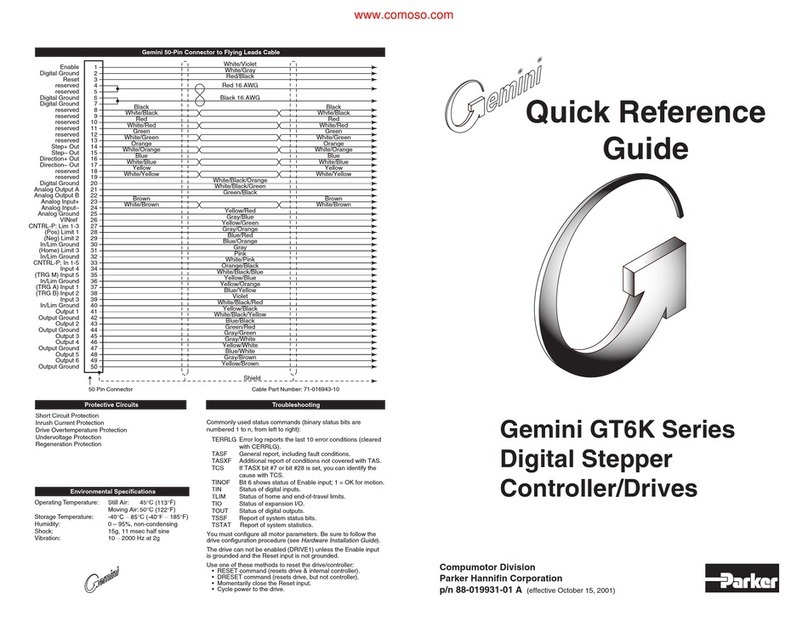
Parker GT Series Manual

Parker

Parker GT Series Manual

Parker Gemini GT6 Series Manual

Parker

Parker Gemini GT6 Series Manual

Parker AC30 series User manual

Parker

Parker AC30 series User manual

Parker Compumotor User manual

Parker

Parker Compumotor User manual

Parker 638 series User manual

Parker

Parker 638 series User manual

Parker DC590PR Series User manual

Parker

Parker DC590PR Series User manual

Parker AC20F Series Assembly instructions

Parker

Parker AC20F Series Assembly instructions

Parker Compax3S User manual

Parker

Parker Compax3S User manual

Parker AC10 series Instructions for use

Parker

Parker AC10 series Instructions for use

Parker Compumotor ZETA6 Series User manual

Parker

Parker Compumotor ZETA6 Series User manual

Parker OSPP-Classic User manual

Parker

Parker OSPP-Classic User manual

Parker AC30 series Installation and operation manual

Parker

Parker AC30 series Installation and operation manual

Parker AC30 series User manual

Parker

Parker AC30 series User manual

Parker XLT50-D User manual

Parker

Parker XLT50-D User manual

Parker ac890 User manual

Parker

Parker ac890 User manual

Parker ViX250IM User manual

Parker

Parker ViX250IM User manual

Parker Gemini GT6K User manual

Parker

Parker Gemini GT6K User manual

Parker Hi-drive User manual

Parker

Parker Hi-drive User manual

Parker AC15 Series Assembly instructions

Parker

Parker AC15 Series Assembly instructions

Parker Compax3S User manual

Parker

Parker Compax3S User manual

Parker P1D-S User manual

Parker

Parker P1D-S User manual

Popular DC Drive manuals by other brands

Danfoss VLT HVAC Drive FC 102 operating guide

Danfoss

Danfoss VLT HVAC Drive FC 102 operating guide

M-Elec GDB-5311A-00 instruction manual

M-Elec

M-Elec GDB-5311A-00 instruction manual

Rockwell Automation Allen-Bradly 1397 user manual

Rockwell Automation

Rockwell Automation Allen-Bradly 1397 user manual

DeVilbiss QS-5001 Service bulletin

DeVilbiss

DeVilbiss QS-5001 Service bulletin

Danfoss VLT AutomationDrive FC 301 Programming guide

Danfoss

Danfoss VLT AutomationDrive FC 301 Programming guide

NetApp E Series manual

NetApp

NetApp E Series manual

Becker L50/17 C SEF I1 Assembly and operating instructions

Becker

Becker L50/17 C SEF I1 Assembly and operating instructions

Infineon EiceDRIVER 6ED Series Application note

Infineon

Infineon EiceDRIVER 6ED Series Application note

UCS TWIN MASTER 24V instructions

UCS

UCS TWIN MASTER 24V instructions

Siemens simovert masterdrives manual

Siemens

Siemens simovert masterdrives manual

Mitsubishi Electric QnA Series manual

Mitsubishi Electric

Mitsubishi Electric QnA Series manual

NEC N8151-139 Startup guide

NEC

NEC N8151-139 Startup guide

Conner 800 MB Travan installation manual

Conner

Conner 800 MB Travan installation manual

Festo ERMO operating instructions

Festo

Festo ERMO operating instructions

BLEMO ER21 user manual

BLEMO

BLEMO ER21 user manual

lumishore SUPRA SY225 Installation and operating instructions

lumishore

lumishore SUPRA SY225 Installation and operating instructions

INVT Goodrive300-21 Series Operation manual

INVT

INVT Goodrive300-21 Series Operation manual

ABB ACS 580-OP manual

ABB

ABB ACS 580-OP manual

manuals.online logo
manuals.online logoBrands
  • About & Mission
  • Contact us
  • Privacy Policy
  • Terms and Conditions

Copyright 2025 Manuals.Online. All Rights Reserved.