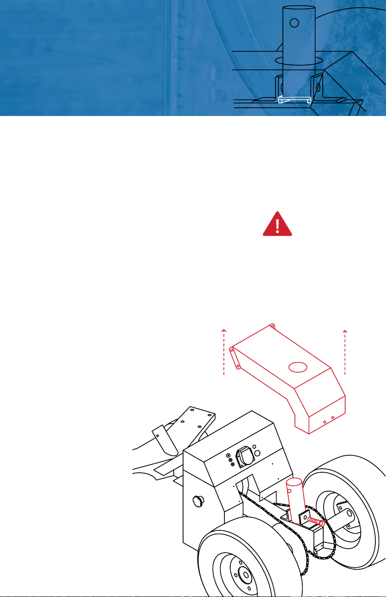
FREEWHEEL
NEUTRAL. MOVE THE DOLLY WITHOUT
POWER WHILE IT IS NOT UNDER LOAD.
backwards before stopping.
Rock the Dolly so the wheels rest in between
these two stop points. Pull on the Knob and turn
it clockwise. Rest the small pin on the outer
Repeat this on the other side of the Dolly.
ENGAGED
DRIVE. FOR CONNECTING TO THE
TRAILER AND PARKING WITH POWER.
Ensure the Dolly is in parking position and ready
to connect to the trailer hitch.
Pull on the Knob and turn it clockwise. Align the
small pin with the corresponding slot. Rock the
Dolly back and forth. The knob will pop in with a
Repeat this on the other side of the Dolly.
REST PIN OUTSIDE
PLACE PIN INSIDE
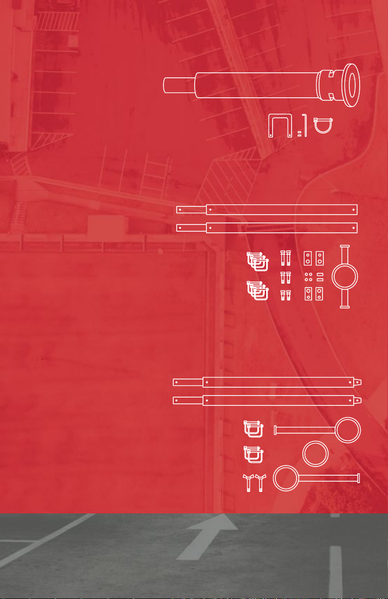
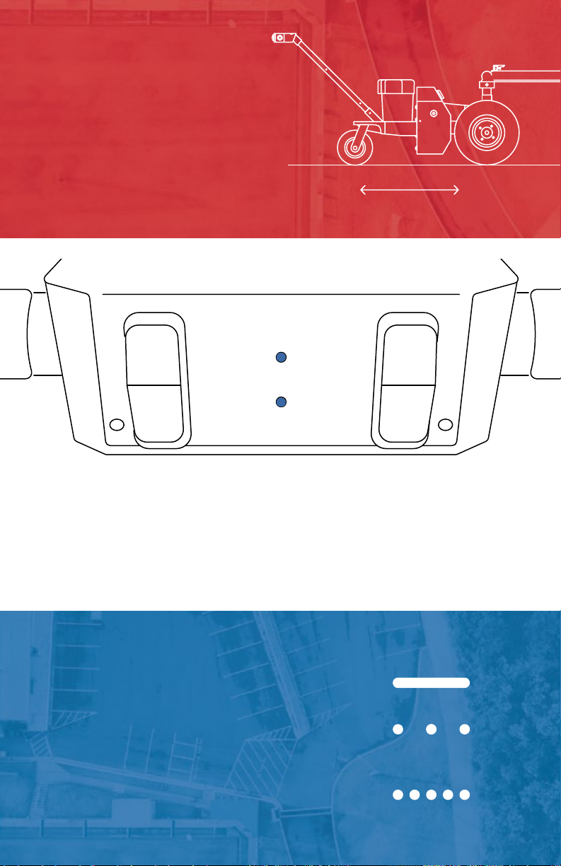
DRIVE MODES:
FREEWHEEL KNOBS
8