MN-36956/MM-1074 Rev 0 (01/15) • Blanket Warming Cabinet Operation & Care Manual • 1
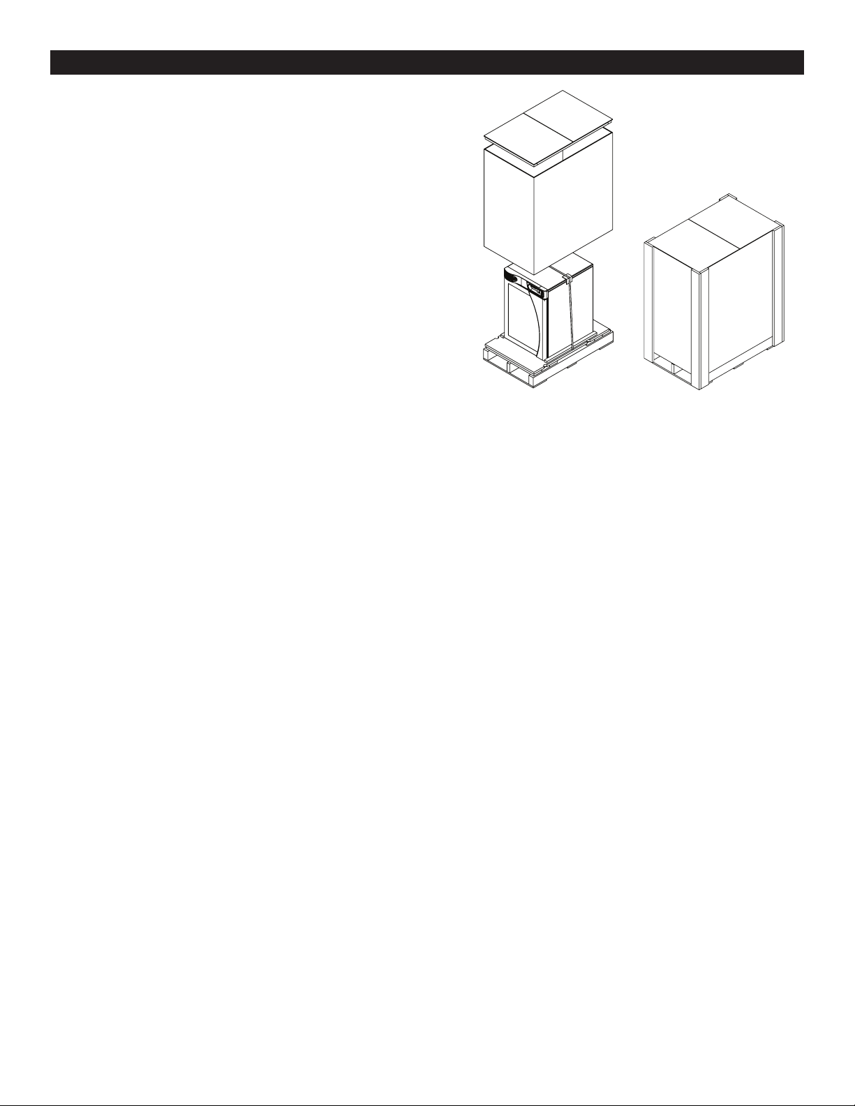
DELIVERY
The warming cabinet has been thoroughly tested and
inspected to insure only the highest quality unit is provided.
Upon receipt, check for any possible shipping damage and
report it at once to the delivering carrier. See Transportation
Damage and Claims section located below.
This appliance, complete with unattached items and
accessories, may have been delivered in one or more
packages. Check to ensure that all standard items and
options have been received with each model as ordered.
Save all the information and instructions packed with the
appliance. Complete and return the warranty card to the
factory as soon as possible to assure prompt service in the
event of a warranty parts and labor claim.
This manual must be read and understood by all people
using or installing the equipment model. Contact the
service department if you have any questions concerning
installation, operation, or maintenance.
Always include both model and serial numbers in your correspondence
regarding the unit.
Model: _____________________________________
Serial Number: _____________________________________
Purchased From: _____________________________________
Date Installed: ____________ Voltage: _______________
SERIAL NUMBER IS REQUIRED FOR ALL INQUIRIES
Transport and Storage Environmental Conditions (not to exceed 15 days)
•Ambient temperature range of -40° to +70°C (-40° to +159°F).
•Relative humidity range of 10% to 95%, non-condensation.
•Atmospheric pressure range of 50KPa to 106KPa.
Operational Environmental Conditions
•Unit must acclimate to room temperature in the environment it will be placed. 24 hours is recommended.
•Recommended environmental temperature range is 15°C to 32°C (60°F to 90°F).
•Recommended relative humidity is above 20%, non-condensation.
ENVIRONMENTAL CONDITIONS
All Pedigo Products, Inc. equipment is
sold F.O.B. shipping point, and when
accepted by the carrier, such shipments
become the property of the consignee.
Should damage occur in shipment, it is a
matter between the carrier and the consignee. In such cases,
the carrier is assumed to be responsible for the safe delivery
of the merchandise, unless negligence can be established on
the part of the shipper.
1. Make an immediate inspection while the equipment is
still in the truck or immediately after it is moved to the
receiving area. Do not wait until after the material is
moved to a storage area.
2. Do not sign a delivery receipt or a freight bill until
you have made a proper count and inspection of all
merchandise received.
3. Note all damage to packages directly on the carrier’s
delivery receipt.
4. Make certain the driver signs this receipt. If he refuses
to sign, make a notation of this refusal on the receipt.
5. If the driver refuses to allow inspection, write the
following on the delivery receipt: Driver refuses to allow
inspection of containers for visible damage.
6. Telephone the carrier’s of ce immediately upon nding
damage, and request an inspection. Mail a written
con rmation of the time, date, and the person called.
7. Save any packages and packing material for further
inspection by the carrier.
8. Promptly le a written claim with the carrier and attach
copies of all supporting paperwork.
We will continue our policy of assisting our customers in
collecting claims which have been properly led and actively
pursued. We cannot, however, le any damage claims for
you, assume the responsibility of any claims, or accept
deductions in payment for such claims.
TRANSPORTATION DAMAGE & CLAIMS