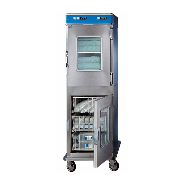
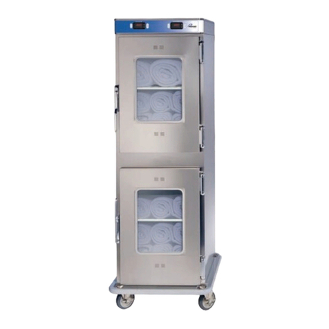
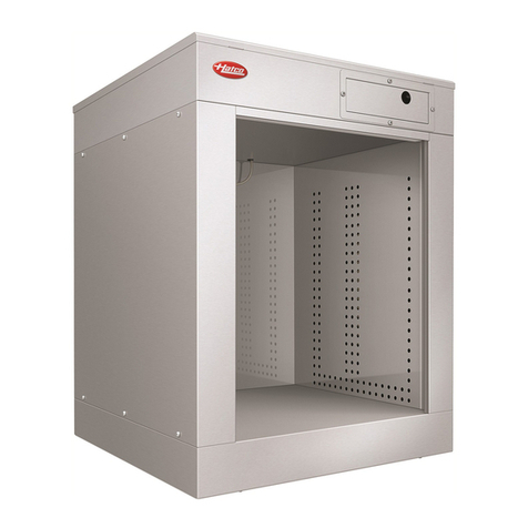
Pedigo P-2420 User manual

Operator’s Manual
Combination
Blanket/Fluid Warmer
P-2420
P-2430
18” Depth and 24” Depth
MN-47424
REV.01
4/21
EN

Comb in ation W arme r ▪ Op erato r ’s Ma nual ▪ MN-47424 ▪ Rev 1 ▪ 4/21
2
Manufacturer’s Information
Copyright © Copyright 4/21 by Pedigo Products, Inc.
All rights reserved.
This manual or any portion thereof may not be reproduced or used in any
manner whatsoever without the express written permission of Pedigo Products,
Inc.
Trademarks All trademarks referenced in this documentation are the property of their
respective owners.
Manufacturer Pedigo Products, Inc.
4000 S.E. Columbia Way
Vancouver, WA 98661, USA
1-800-822-3501
www.pedigo-usa.com
Original instructions The content in this manual is written in American English.

FOREWORD
Combina tion W armer ▪ Op erat or ’s Manua l ▪ MN -47424 ▪ Rev 1 ▪ 4/2 1
3
FOREWORD
Thank you for your Purchase!
This warmer has been thoroughly tested and inspected to ensure only the
highest quality is provided. We supply the most durable, convenient, efficient
and safe warming equipment on the market. All warmers are manufactured and
fully inspected in the USA with a commitment to quality.
Pedigo Repair Service
Call Call 262-509-6517 to reach our service call center for immediate access to local
authorized service agencies. This service is provided exclusively for Pedigo
Product, Inc. equipment and is available throughout the United States.

FOREWORD
Comb in ation W arme r ▪ Op erato r ’s Ma nual ▪ MN-47424 ▪ Rev 1 ▪ 4/21
4
This page intentionally left blank.

FOREWORD
Combina tion W armer ▪ Op erat or ’s Manua l ▪ MN -47424 ▪ Rev 1 ▪ 4/2 1
5
TABLE OF CONTENTS
Manufacturer’s Information . . . . . . . . . . . . . . . . . . . . . . . . 2
Foreword 3
Thank you for your Purchase! . . . . . . . . . . . . . . . . . . . . . . . 3
Pedigo Repair Service . . . . . . . . . . . . . . . . . . . . . . . . . . . . 3
Safety 7
The Meaning of Signal Words . . . . . . . . . . . . . . . . . . . . . . . 7
Safety Precautions. . . . . . . . . . . . . . . . . . . . . . . . . . . . . . 8
Labels 11
Label Locations . . . . . . . . . . . . . . . . . . . . . . . . . . . . . . . 11
Specifications 13
Specification Information . . . . . . . . . . . . . . . . . . . . . . . . . 13
Dimension Drawings . . . . . . . . . . . . . . . . . . . . . . . . . . . . 14
Installation 25
How to Unpack the Warmer . . . . . . . . . . . . . . . . . . . . . . . . 25
How to Install the Warmer . . . . . . . . . . . . . . . . . . . . . . . . . 26
How to Install the Built-In Warmer into the Wall . . . . . . . . . . . . 28
Operation 31
Preparing the Warmer for First Use. . . . . . . . . . . . . . . . . . . . 31
How to Turn On and Turn Off the Warmer . . . . . . . . . . . . . . . . 32
How to Operate the TriMode Warmer . . . . . . . . . . . . . . . . . . 33
How to Change the Temperature Scale. . . . . . . . . . . . . . . . . . 35
How to Change the Sound Settings . . . . . . . . . . . . . . . . . . . . 35
How to Lock and Unlock the Controller. . . . . . . . . . . . . . . . . . 36
How to Download Temperature Data from the Warmer . . . . . . . . 37
Maintenance 41
Maintenance Schedule . . . . . . . . . . . . . . . . . . . . . . . . . . . 41
How to Clean the Warmer . . . . . . . . . . . . . . . . . . . . . . . . . 43
Warmer Disposal / Decommissioning . . . . . . . . . . . . . . . . . . 45
Troubleshooting 47
What to do if a Power Interruption Occurs. . . . . . . . . . . . . . . . 47
What to do if the Alarm Indicator Light Flashes . . . . . . . . . . . . . 48
Error Codes. . . . . . . . . . . . . . . . . . . . . . . . . . . . . . . . . . 49
How to Replace a Fuse . . . . . . . . . . . . . . . . . . . . . . . . . . . 53
Electrical Information 55
Warranty 59
Warranty . . . . . . . . . . . . . . . . . . . . . . . . . . . . . . . . . . . 59

FOREWORD
Comb in ation W arme r ▪ Op erato r ’s Ma nual ▪ MN-47424 ▪ Rev 1 ▪ 4/21
6
This page intentionally left blank.

SAFETY
Combina tion W armer ▪ Op erat or ’s Manua l ▪ MN -47424 ▪ Rev 1 ▪ 4/2 1
7
SAFETY
The Meaning of Signal Words
This manual contains signal words where needed. These signal words must be
obeyed to reduce the risk of death, personal injury, or equipment damage. The
meaning of these signal words is explained below.
DANGER
Danger indicates a hazardous situation which, if not avoided,
will result in serious injury or death.
WARNING
Warning indicates a hazardous situation which, if not avoided,
could result in serious injury or death.
CAUTION
Caution indicates a hazardous situation which, if not avoided,
could result in minor or moderate injury.
NOTICE
Notice indicates a situation which, if not avoided, could result
in property damage.
NOTE: Note indicates additional information that is important to a
concept or procedure.

SAFETY
Comb in ation W arme r ▪ Op erato r ’s Ma nual ▪ MN-47424 ▪ Rev 1 ▪ 4/21
8
Safety Precautions
Before you begin Read and understand all instructions in this manual.
Electrical precautions Obey these electrical precautions when using the warmer:
▪Connect the warmer to a properly grounded outlet. Do not use the warmer if it is
not properly grounded. Consult an electrician if there is any doubt that the outlet
used is properly grounded.
▪Keep the cord away from hot surfaces.
▪Do not attempt to service the warmer or its cord and plug, when plugged in.
▪Do not operate the warmer if it has a damaged cord or plug.
▪Do not immerse the cord or plug in water.
▪Do not let the cord hang over the edge of a table or counter.
▪Do not use an extension cord.
Usage precautions Obey these usage precautions when using the warmer:
▪Only use this warmer for its intended use of warming medical solution bags,
bottles, and/or blankets. Follow facility and solution manufacturer guidance
regarding warming temperature for any item to be placed in the warmer.
▪Do not use this warmer for warming blood or blood products.
▪Do not cover or block any of the openings of this warmer.
▪Do not use this warmer in a wet location.
▪Only clean the warmer when the power cord is unplugged.
▪Do not use corrosive chemicals when cleaning the warmer.
▪Do not use the warmer cavity for storage.
▪Do not remove exterior panels from the warmer or attempt repairs. The warmer
has no user-serviceable internal components. Only perform routine cleaning and
maintenance procedures specifically described in this manual. Inspection and
servicing of internal components must only be performed by qualified service
personnel.
▪Only a qualified Pedigo service representative may make modifications to the
warmer. Modifications to the warmer could be hazardous to users and patients.
Operator training All personnel using the warmer must have proper operator training. Before
using the warmer:
▪Read and understand the operating instructions contained in all the
documentation delivered with the warmer.
▪Know the location and proper use of all controls.
▪Keep this manual and all supplied instructions, diagrams, schematics, parts lists,
notices, and labels with the warmer if the warmer is sold or moved to another
location.

SAFETY
Combina tion W armer ▪ Op erat or ’s Manua l ▪ MN -47424 ▪ Rev 1 ▪ 4/2 1
9
Operator
qualifications
Only trained personnel with the following operator qualifications are permitted
to use the warmer:
▪Have received proper instruction on how to use the warmer.
▪Are familiar with the purpose, limitations, and associated hazards of the warmer.
The warmer must not be used by:
▪People impaired by drugs or alcohol.
Condition of warmer Only use the warmer when:
▪All controls operate correctly.
▪The warmer is installed correctly.
▪The warmer is clean.
▪The warmer labels are legible.
Servicing the warmer ▪Obey precautions in the manual, on tags, and on labels attached to or shipped
with the warmer.
▪Only trained personnel are permitted to service or repair the warmer. Repairs
that are not performed by a trained technician, or the use of non-factory parts,
will void the warranty and relieve all liability.
▪Any troubleshooting guides and components views included with this manual
are for reference only and are intended for use by qualified and trained service
technicians.
▪To prevent serious injury, death or property damage, have the warmer inspected
and serviced at least every twelve (12) months by a trained technician.
▪Contact Pedigo for the authorized service partner in your area.
Incident notice ▪Any serious incident that has occurred in relation to the warmer should be
reported to the manufacturer and the competent authority of the Member State
in which the user and/or patient is established.

SAFETY
Comb in ation W arme r ▪ Op erato r ’s Ma nual ▪ MN-47424 ▪ Rev 1 ▪ 4/21
10
This page intentionally left blank.

LABELS
Combina tion W armer ▪ Op erat or ’s Manua l ▪ MN -47424 ▪ Rev 1 ▪ 4/2 1
11
LABELS
Label Locations
EC-PHD-011147
a
c
d
b

LABELS
Comb in ation W arme r ▪ Op erato r ’s Ma nual ▪ MN-47424 ▪ Rev 1 ▪ 4/21
12
1
Security seal
2
Electrical warning label
3
Pedigo contact information
4
Quality inspected
Security Seal
Security Seal
Security Seal
Security Seal
Security Seal
Security Seal
Security Seal
Security Seal
LA-47138
F1, F2 = 10A, 250V MAX
F
F

SPECIFICATIONS
Combina tion W armer ▪ Op erat or ’s Manua l ▪ MN -47424 ▪ Rev 1 ▪ 4/2 1
13
SPECIFICATIONS
Specification Information
Transportation and
storage conditions
▪Ambient temperature range of -40°F to +159°F (-40°C to +70°C).
▪Relative humidity range of 10% to 95%, non-condensing.
▪Atmospheric pressure range of 7.25 psi to 15.37 psi (50kPa to 106kPa).
Operating conditions ▪The warmer must acclimate to the room temperature it will be placed in—24
hours is recommended.
▪The recommended environmental temperature range is 60°F to 90°F
(15°C to 32°C).
▪The recommended relative humidity is above 20%, non-condensing.
Standards for
electrical equipment
▪Medical equipment listed by Underwriters Laboratories with respect to
electrical shock, fire, and mechanical hazards only, in accordance with UL
61010-1 and CAN/CSA C22.2 No. 61010-1.
▪Grounding reliability can only be achieved when the appliance is
connected to an equivalent receptacle marked “Hospital Grade.”
▪IP-XO ordinary
Model P-2420
18” Depth
P-2430
24” Depth
Intended use Warming blankets, irrigation or injection fluids
Weight Net: 105 lb (48 kg)
Ship: 185 lb (84 kg)
Net: 135 lb (61 kg)
Ship: 215 lb (98 kg)
Storage cavity
capacity
TriMode cavity: 24 1-liter bottles
or 20 1-liter bags, or
9–12 blankets (4.75 ft3)
TriMode cavity: 30 1-liter bottles
+ 36 1/2 liter-bottles, 48 1-liter
bags, or 10–14 blankets (5.5 ft3)
Temperature
range
Irrigation fluids (IRR): 90°F to 150°F (32°C to 66°C)
Injection fluids (INJ): 90°F to 104°F (32°C to 40°C)
Blanket (BLNKT): 90°F to 160°F (32°C to 71°C)
Clearance
requirements
0.5” (12.7mm) from rear
0.5” (12.7mm) from top
0.5” (12.7mm) from sides
E471516
Protective Earth
Ground Symbol

SPECIFICATIONS
Comb in ation W arme r ▪ Op erato r ’s Ma nual ▪ MN-47424 ▪ Rev 1 ▪ 4/21
14
Dimension Drawings
18” Depth P-2420 shown with Standard Feet
EC-DIM-011150
IEC Cord Inlet
Cord length: 6 (1.83m) (est.)
30.0" (762mm)
30.0" (762mm)
26.6" (674.5mm)
24.44" (620.7mm)
60.0" (1524mm)
51.12" (1298.6mm)
24.41" (620mm)
CAVITY
INSERT
16.43" (417.4mm)
INSERT
25.12" (638.2mm)
18.27" (464mm)
CAVITY
16.9" (429.34mm)
CAVITY
21.12" (536.6mm)
22.6" (573.4mm)
IEC Cord Inlet
21.85
" (555mm)
22.7" (575.5mm)

SPECIFICATIONS
Combina tion W armer ▪ Op erat or ’s Manua l ▪ MN -47424 ▪ Rev 1 ▪ 4/2 1
15
18” Depth P-2420 shown with Optional Caster Plate
18” Depth P-2420 shown with Optional Caster Plate with
Bumpers
EC-DIM-011162
29.6" (752mm)
5.0" (128mm)
26.9" (683mm)
IEC Cord Inlet
EC-DIM-011165
29.6" (752mm)
5.0" (128mm)
26.9" (683mm)
IEC Cord Inlet
32.5" (825.5mm) 24.75" (629mm)

SPECIFICATIONS
Comb in ation W arme r ▪ Op erato r ’s Ma nual ▪ MN-47424 ▪ Rev 1 ▪ 4/21
16
18” Depth P-2420 Built-In
EC-DIM-011156
30.0" (762mm)
30.0" (762mm)
26.6" (674.5mm)
24.44" (620.7mm)
60.0" (1524mm)
47.55" (1207.8mm)
24.34" (618.24mm)
CAVITY
INSERT
16.43" (417.4mm)
INSERT
18.27" (464mm)
CAVITY
16.9" (429.34mm)
CAVITY
18.8" (479.2mm)
20.4" (518.7mm)
29.0" (736.6mm)
BUILT-IN WIDTH
17.5" (444.5mm)
BUILT-IN DEPTH
23.75" (603.25mm)
BUILT-IN HEIGHT

SPECIFICATIONS
Combina tion W armer ▪ Op erat or ’s Manua l ▪ MN -47424 ▪ Rev 1 ▪ 4/2 1
17
18” Depth P-2420 Built-In Cutout Specifications and Inlet
Locations
Continued on next page
CAUTION: Fire hazard.
Supply wires must be rated for a minimum wire temperature of
80°C.
NOTICE
Built-in units must be hardwired to the facility mains with a 15A breaker switch.
Breaker* Wire Size** Wire Temperature
15A 12 AWG (1mm2) 80°C (minimum)
*Electrical connections must meet applicable codes.
**IEC 60335 minimum.
Cutout Specifications Inlet Options
Height 24.0” (609.6mm) 1Back of warmer
Width 29.25” (743mm) 2Top of warmer
Depth 18.0” (457.2mm) 3Left side of warmer
Top of unit clearance 12.0” (304.75mm) ——

SPECIFICATIONS
Comb in ation W arme r ▪ Op erato r ’s Ma nual ▪ MN-47424 ▪ Rev 1 ▪ 4/21
18
Continued from previous page
EC-DIM-011159
24.0
"
(609.6mm)
29.25
"
(743mm)
18.0
"
(457.2mm)
3.0
"
(76.2mm)
3.0
"
(76.2mm)
6.0
"
(152.4mm)
1
23

SPECIFICATIONS
Combina tion W armer ▪ Op erat or ’s Manua l ▪ MN -47424 ▪ Rev 1 ▪ 4/2 1
19
24” Depth P-2430 shown with Standard Feet
NOTE: 1 shelf standard for 24” depth P-2430. 1 basket and 1 shelf
optional for 24” depth P-2430.
EC-DIM-011168
IEC Cord Inlet
Cord length: 6 (1.83m) (est.)
30.0" (762mm)
30.0" (762mm)
26.6" (675mm)
24.47" (621.5mm)
60.0" (1524mm)
57.12" (1298.6mm)
24.41" (620mm)
CAVITY
INSERT
17.52" (445mm)
INSERT
25.12" (638.2mm)
18.27" (464mm)
CAVITY
19.73" (501mm)
CAVITY
27.12" (689mm)
22.6" (573.4mm)
IEC Cord Inlet
21.85
" (555mm)
21.8" (554mm)
4.4" (112mm)
15.6" (396mm)
28.5" (724mm)

SPECIFICATIONS
Comb in ation W arme r ▪ Op erato r ’s Ma nual ▪ MN-47424 ▪ Rev 1 ▪ 4/21
20
24” Depth P-2430 shown with Optional Basket and Shelf
with Caster Plate
24” Depth P-2430 shown with Optional Basket and Shelf
with Bumpers
NOTE: 1 shelf standard for 24” depth P-2430. 1 basket and 1 shelf
optional for 24” depth P-2430.
EC-DIM-011171
29.6" (752mm)
5.0" (128mm)
26.9" (683mm)
IEC Cord Inlet
17.0" (432mm)
USABLE HEIGHT
8.25" (210mm)
ADJUSTABLE
SHELF HEIGHT
NOTE: 1 shelf standard for 24” depth P-2430. 1 basket and 1 shelf
optional for 24” depth P-2430.
EC-DIM-011174
29.6" (752mm)
5.0" (128mm)
26.9" (683mm)
IEC Cord Inlet
32.75" (832mm) 30.8" (782.5mm)
This manual suits for next models
1
Table of contents
Other Pedigo Food Warmer manuals

Pedigo
Pedigo P-2040-S User manual

Pedigo
Pedigo P-2040 User manual

Pedigo
Pedigo P-2140 User manual

Pedigo
Pedigo P-2030-S User manual

Pedigo
Pedigo P-2012 User manual

Pedigo
Pedigo Elite Series User manual

Pedigo
Pedigo P-2010-S User manual

Pedigo
Pedigo WARMWATCH P-2148 User manual

Pedigo
Pedigo P-2110 User manual

Pedigo
Pedigo P-2150 User manual
Popular Food Warmer manuals by other brands

APW Wyott
APW Wyott CCW Installation and operating instructions

Garland
Garland EFW500 Installation and operation manual

Wells
Wells SS-10ULT Specifications

CookTek
CookTek SinAqua IHW061-22 Installation, operation and owner's manual

Star
Star 3W SERIES Installation and operation instructions

Honey Can Do
Honey Can Do SHO-05254 manual