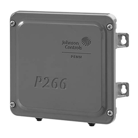
Penn P470 Manual

Part No. 24-7664-2004, Rev. C
Issued October 2018
t.
1
P470 Electronic Pressure Control with Display Product/Technical Bulletin
The P470 Electronic Pressure Control with Display is a
single-stage, on and off, electronic pressure control
with a single-pole, double-throw (SPDT) output relay.
You can field-set the P470 control to operate in one of
the following three pressure ranges, as either an open-
high or open-low control: 0 psi to 100 psi, 0 psi to 500
psi, or 50 psi to 750 psi.
The P470 control has a large LCD that displays the
sensed pressure, other system-status indicators, and
adjustable setpoints in the programming mode. The
P470 control has a lockable, three-button touchpad for
adjusting setpoints, and a front-panel LED that
indicates the output relay status.
The P470 control uses a P499 or P599 Series
Electronic Pressure Transducer and a WHA-PDK3
wiring harness to sense system pressure. This
arrangement eliminates almost all refrigerant leaks
because there are no capillaries or bellows to break or
fail. See Ordering information for information about
specified pressure transducers.
Features and benefits
•Easy to read LCD—Clearly displays the sensed pressure and other control information. In many situations,
pressure may be monitored without applying gauges to the controlled equipment.
•Three field-selectable pressure ranges between 0 psi and 750 psi—Flexibly covers most HVACR pressure
applications with three field-selectable pressure ranges: 0 psi to100 psi with 5 psi minimum differential, and 0
psi to 500 psi or 50 psi to 750 psi with 20 psi minimum differential.
•24 VAC and 120 VAC or 208/240 VAC models—Increases application options, with two controls that cover
most common voltages.
•Lockable, three-button, front-panel touchpad—Deters tampering and over-adjustment of control settings by
unauthorized personnel.
•Built-in, adjustable, anti-short cycle delay—Reduces compressor short cycling and nuisance lockouts that
can extend compressor life.
•Uses an economical and versatile transducer and wiring harness—Eliminates many of the constraints of
capillary control applications and supports up to a 100 ft (30.5 m) cable between a control and transducer.
Figure 1: P470 Electronic Pressure Control with
transducer and wiring harness
P470 Electronic Pressure Control with Display
Product/Technical Bulletin
Code No. LIT-125528

P470 Electronic Pressure Control with Display Product/Technical Bulletin
2
Application
Application options
The P470 control is designed for direct or pilot duty on
and off control of refrigeration and HVAC loads based
on system pressure.
The P470 control’s overall setpoint range is
0 psi to 750 psi. The available operating ranges are
0 psi to 100 psi, 0 psi to 500 psi, and 50 psi to 750 psi,
depending on which P499 or P599 transducer you wire
to the control.
Note: Each of the P470 control’s three field-
selectable, operating pressure ranges require a
specific P499 or P599 transducer to operate properly.
See Table 1 for more information.
You can use the P499 or P599 transducer with any fluid
or vapor that is compatible with 17-4PH stainless steel,
including all non-corrosive refrigerants and ammonia.
The P470 control can replace a variety of
electromechanical pressure controls, and provides a
clear LCD display of the controlled equipment
pressure. You can mount the transducer up to
100 ft (30.5 m) away from the control using three-wire
shielded cable; this provides greater installation
versatility, and eliminates many of the constraints of
capillary tubes found on electro-mechanical pressure
controls.
You can use a maximum of four P470 controls wired to
a single P499 or P599 transducer. For example, high-
pressure control and condenser fan cycling can use a
common transducer in conjunction with two P470
controls to control high-side pressure. You can connect
the P470 controls to a single transducer on the suction
manifold to stage four compressors on a refrigeration
rack. See Figure 7.
Operation overview
The P470 control uses a P499 or P599 transducer to
sense pressure. The control’s operating pressure
range depends on the transducer model that you select
and the position of the pressure range jumpers. See
Positioning the jumpers and Table 1.
The P499 or P599 transducer is mounted to a pressure
tap point on the refrigerant system. The transducer
generates a 0.5 VDC to 4.5 VDC ratiometric signal that
the P470 control converts to a psi value. Refer to the
P499 Series Electronic Pressure Transducers Product/
Technical Bulletin (LIT-12011190) or the P599 Series
Electronic Pressure Transducer Product/Technical
Bulletin (LIT-12012446) for more information.
The sensed psi value refreshes every two seconds and
displays on the LCD with other control status
information during normal operation, as shown in
Figure 3.
When the pressure at the transducer reaches the cut-in
setpoint, the output relay is energized, the front-panel
LED lights, N.O. contacts close, and N.C. contacts
open. When the transducer reaches the cut-out
setpoint, the output relay is de-energized, the LED
goes off, and the contacts return to their normal
positions.
IMPORTANT: Use this P470 Electronic Pressure
Control only as an operating control. Where failure or
malfunction of the P470 control could lead to personal
injury or property damage to the controlled equipment
or other property, additional precautions must be
designed into the control system. Incorporate and
maintain other devices, such as supervisory or alarm
systems or safety or limit controls, intended to warn of
or protect against failure or malfunction of the P470
control.
IMPORTANT : Utiliser ce P470 Electronic Pressure
Control uniquement en tant que dispositif de
contrôle de fonctionnement. Lorsqu'une défaillance
ou un dysfonctionnement du P470 control risque de
provoquer des blessures ou d'endommager l'équi-
pement contrôlé ou un autre équipement, la concep-
tion du système de contrôle doit intégrer des
dispositifs de protection supplémentaires. Veiller
dans ce cas à intégrer de façon permanente
d'autres dispositifs, tels que des systèmes de super-
vision ou d'alarme, ou des dispositifs de sécurité ou
de limitation, ayant une fonction d'avertissement ou
de protection en cas de défaillance ou de dysfonc-
tionnement du P470 control.

P470 Electronic Pressure Control with Display Product/Technical Bulletin
3
Dimensions
LCD
The sensed pressure displays on the LCD during
normal operation. See Figure 3.
S1 or S2 displays in the upper-right corner of the LCD
when the control operates in the primary, S1, or
secondary, S2, setpoint. You can also see if the control
is operating as an open-high or open-low control, as
shown in Figure 3. The LCD also shows if the control is
in anti-short cycle delay. See Anti-short cycle delay.
When you adjust the control, the LCD shows the
adjustable setpoints and their values. See Table 2 and
the Adjustments section for information about display
codes and how to change the settings. After 30
seconds of touchpad inactivity, the control and display
return to normal operation. See Figure 3.
P470 control settings
You can use the P470 control to establish a variety of
control settings, position jumpers inside the control and
use the three-button touchpad to change setpoint
values. For more instructions, see Positioning the
jumpers and Changing setpoint values and anti-short
cycle delay time-interval.
.
Touchpad adjustable setpoints
Cut-in
Cut-in establishes the pressure value in psi at which
the output relay is energized, which closes the N.O.
contacts, opens the N.C. contacts, and the LED is on.
Figure 2: P470 control dimensions in inches (mm)
Figure 3: P470 control operating display
PSI
Indicates if the control is operating with either
the Primary ( ) or Secondary ( ) setpoints.
(D only the indicator for the
active setpoints in use is visible in black.
)
S1 S2
uring normal operation
is shown
here in gray to illustrate its position on the LCD.
S2
Indicates pressure (in psi)
sensed at the transducer.
Indicates if the control is operating as an
open-low or open-high pressure control.
(During normal operation only one of the two icons
is visible in black. The open-high icon is shown
here in gray to illustrate its position on the LCD.)
FIG:P470_dsply

P470 Electronic Pressure Control with Display Product/Technical Bulletin
4
Cut-out
Cut-out establishes the pressure value in psi at which
the output relay is de-energized, returning the contacts
to their normal positions, and the LED is off.
When you establish the cut-in and cut-out values, the
P470 control automatically determines the control
operation and either an Open-high or Open-low icon
displays in the lower right of the LCD during normal
operation. See Figure 3.
The cut-in, ci1, and cut-out, co1, values establish the
primary setpoints, S1. You can also set a secondary
set, S2, of cut-in, ci2, and cut-out, co2, values. Use a
user-supplied SPST switching device, such as a
control-clock or temperature control, to enable the S2
setpoints. See Secondary cut-in and cut-out setpoints
for more information.
Anti-short cycle delay
Anti-short cycle delay establishes the minimum time
that the controlled equipment remains off before it
starts again. The anti-short cycle delay activates when
the output relay de-energizes. The output relay cannot
re-energize until the user-set delay time elapses
because of the delay. When the delay activates, the
LCD alternately shows the sensed pressure value and
Ax, where x is the number of minutes of remaining
delay time. You can program the anti-short cycle delay
for zero to nine minutes in one minute increments.
Note: A0 indicates that the control is in the final
minute of the delay sequence.
Note: Any power interruption to the control also
activates the anti-short cycle delay.
Secondary cut-in and cut-out setpoints
Secondary cut-in and cut-out setpoints establish a
second set of cut-in and cut-out values, which activate
when a circuit closes between the binary input
terminals, SP2 and COM, on the upper terminal block
(TB3). When the secondary setpoints activate, S2
displays instead of S1 in the upper-right corner of the
LCD. See Figure 3.
Settings established by jumper position
Establish two of the P470 control settings by
positioning jumpers inside the control. The following
sections contain more information about these
parameters. For instructions about how to position the
jumpers, see Positioning the jumpers.
Pressure range jumper
Pressure range jumper positions establish the
operational pressure range of the P470 control. Each of
the three pressure ranges requires a specific P499 or
P599 transducer with a matching range. See Table 1
for transducer model and pressure range information.
Position the pressure range jumpers to operate the
control in a 0 psi to 100 psi, 0 psi to 500 psi, or 50 psi to
750 psi range. See Positioning the jumpers and
Table 1.
Touchpad lock jumper
Touchpad lock jumper position establishes if you can
use the front panel to adjust the control. Locking out the
touchpad helps deter tampering or accidental changes
to the established setpoints.
Note: The P470 control settings are non-volatile and
remain in the control’s memory during power
interruptions.
Mounting
Note: When you mount the P470 control to a rigid
conduit, attach the hub to the conduit before you
secure the hub to the control enclosure.
The P470 control has a National Electrical
Manufacturers' Association (NEMA) 1 plastic enclosure
with four key-slot mounting holes on the back for
surface mounting. The mounting hole pattern on the
P470 control is identical to the System 450 modules
and other Johnson Controls® and PENN® controls.
You can mount the P470 control on a 35 mm DIN rail.
See Dimensions for more information. The P470
control is not position sensitive, but mount the control
for convenient wiring, setup, and adjustment.

P470 Electronic Pressure Control with Display Product/Technical Bulletin
5
Wiring
Observe the following guidelines and refer to the wiring
diagrams when you wire the control. See Figure 4,
Figure 5, Figure 6, and Figure 7.
• All wiring must conform to the National Electric
Code (NEC) and local regulations.
• Use copper conductors only.
• Input power and output relay terminal blocks,
TB1 and TB2, accept a 12 AWG or smaller wire.
The sensor terminal block, TB3, accepts a 16 AWG
or smaller wire.
• The minimum required wire insulation rating is
90°C.
• The maximum wire length between the control and
controlled equipment is 50 ft (15.2 m).
The P470 control uses a P499 or P599 transducer to
generate the 0.5 VDC to 4.5 VDC input signal. The
transducer is wired to the control at the terminal block,
TB3, on the upper-left of the circuit board. See
Figure 4, Figure 5, Figure 6, and Figure 7 when you
wire the transducer to the control. Connect the cable
shield to COM on the TB3 terminal block. Do not
connect the other end of the cable shield to anything.
Use 22 AWG, three-wire, shielded cable to extend the
wiring harness. The maximum length of shielded cable
is 100 ft (30.5 m) between the transducer and the
control. Refer to the P499 Series Electronic Pressure
Transducers Product/Technical Bulletin (LIT-12011190)
or the P599 Electronic Pressure Transducer Product/
Technical Bulletin (LIT-12012446) for more information
about how to install and wire the pressure transducer.
!
WARNING: Risk of Electric Shock.
Disconnect the power supply before making
electrical connections. Contact with
components carrying hazardous voltage can
cause electric shock and may result in severe
personal injury or death.
AVERTISSEMENT : Risque de décharge
électrique.
Débrancher l'alimentation avant de réaliser
tout branchement électrique. Tout contact
avec des composants conducteurs de
tensions dangereuses risque d'entraîner une
décharge électrique et de provoquer des
blessures graves, voire mortelles.
IMPORTANT: Do not wire more than four P470
controls to a single P499 or P599 transducer. Use a
three-wire cable that is 15 ft (4.5 m) or less to
connect the controls. See Figure 7.
Figure 4: Typical wiring for 24 VAC applications
of the P470FB-1 Pressure Control

P470 Electronic Pressure Control with Display Product/Technical Bulletin
6
Adjustments
This section provides instructions for setting up and
adjusting the P470 control using the internal jumpers
and front panel touchpad.
Positioning the jumpers
The P5 jumper-pin terminal has a single pair of jumper
pins and is used to lock or unlock the touchpad. The P6
jumper-pin terminal has two pairs of jumper pins and
establishes the control’s operating pressure range.
To position a jumper in the Installed position, place the
jumper on both pins. To position a jumper in the
Removed position, place the jumper on one pin only.
Save the jumper in case it is required in the future. See
Figure 8.
Figure 5: Typical wiring for 120 VAC
applications of the P470EB-1 Pressure Control
Figure 6: Typical wiring for 208/240VAC
applications of the P470EB-1 Pressure Control
Figure 7: Wire multiple P470 controls in parallel
with a single transducer
Figure 8: Positioning the jumpers

P470 Electronic Pressure Control with Display Product/Technical Bulletin
7
Set the jumpers as shown in the following steps, and
use Figure 8 and Figure 9 as guides.
1. Disconnect all power sources to the P470 control.
2. To remove the control’s cover, loosen the
four captive cover screws.
3. Position the jumpers to set the required operating
pressure range and lock or unlock the touchpad.
4. Replace the cover, and restore power to the
control.
IMPORTANT: The P470 control’s three field-
selectable operating pressure ranges require
specific P499 or P599 transducer models to operate
properly. Do not use a transducer model that is not
specified for the P470 control’s field-selected
operating pressure range. See Table 1.
Figure 9: Jumper positions for locking
touchpad and establishing the P470 control’s
operating pressure range
Table 1: Specified transducer models, required jumper positions with the resulting operating pressure
ranges, and factory settings at startup
Transducer
model number
1
Pressure
connection
fitting
Required
P6 jumper
positions
Control’s
operating
pressure
range
Factory
set
cut-in
2
(psi)
Factory set
cut-out
2
(psi)
Minimum
setpoint
differential
Factory set
setpoint
differential
P499RAP-101C
P499RAP-101K
P599RAPS101C
P599RAPS101K
1/8 in. NPT
male
JMP1
removed
JMP2
removed
0 psi–100
psi
S1–40
S2–45
S1–20
S2–25
5 psi 20 psi
P499RCP-101C
P499RCP-101K
P599RCPS101C
P599RCPS101K
1/4 in. SAE
female
(Schrader®
fitting)
P499RAP-105C
P499RAP-105K
P599RAPS105C
P599RAPS105K
1/8 in. NPT
male
JMP1
installed
JMP2
removed
0 psi–500
psi
S1–250
S2–220
S1–190
S2–160
20 psi 60 psi
P499RCP-105C
P499RCP-105K
P599RCPS105C
P599RCPS105K
1/4 in. SAE
female
(Schrader
fitting)
P499RAP-107C
P499RAP-107K
P599RAPS107C
P599RAPS107K
1/8 in. NPT
male
JMP1
removed
JMP2
installed
50 psi–750
psi
S1–250
S2–220
S1–190
S2–160
20 psi 60 psi
P499RCP-107C
P499RCP-107K
P599RCPS107C
P599RCPS107K
1/4 in. SAE
female
(Schrader
fitting)
1. C suffix is transducer only. K suffix is transducer with 2 m long wiring harness.
2. S1 = primary setpoint value and S2 = secondary setpoint value

P470 Electronic Pressure Control with Display Product/Technical Bulletin
8
Changing setpoint values and anti-short cycle
delay time-interval
To change the P470 control setpoint values and anti-
short cycle delay time-interval, complete the following
steps:
1. Press Menu once. ci1 flashes, which indicates cut-
in setpoint 1.
• If you want to change cut-in setpoint 1,
proceed to Step 3.
• If you want to change another setpoint value or
the anti-short cycle delay time-interval,
proceed to Step 2.
Note: After 30 seconds of inactivity, the operating
pressure display appears.
2. Press Up once to go to cut-out setpoint 1, co1.
Press Up again to go to cut-in setpoint 2, ci2, and
again to go to cut-out setpoint 2, co2, and once
more to go to anti-short cycle delay, ASd.
• Press Up again to go back to cut-in setpoint 1,
or to scroll through the parameters in reverse
order, press Down repeatedly.
3. When the parameter that you want to change
flashes on the display, press Menu once. The
current pressure setpoint value or delay time-
interval displays.
4. To change the setpoint value or time-interval, press
Up or Down.
5. To save the new value, press Menu. The operating
pressure display appears.
Note: If you do not press Menu within 30 seconds
after you change a setpoint or time-interval value,
the control returns to the previously programmed
setpoint or time interval value.
Scrolling through the adjustable setpoints
Figure 10 shows the order of the adjustable setpoints
that display when you scroll through them using Up or
Down. To scroll and display the adjustable setpoints in
a clockwise direction, press Up. To scroll through and
display the adjustable setpoints in a counterclockwise
direction, press Down.
IMPORTANT: Before you apply power to the
control and controlled equipment, make sure
installation, wiring, and control settings are
according to the application requirements. Power
the equipment and observe the controlled
equipment for at least three complete operating
cycles before leaving the installation.
Figure 10: Order of the adjustable setpoints and
time delay interval

P470 Electronic Pressure Control with Display Product/Technical Bulletin
9
Troubleshooting
Determine the correct supply voltage for the control
that you are troubleshooting. See Figure 4, Figure 5,
and Figure 6 for the wiring diagram and terminal
designations for the control.
See Figure 3 and Table 2 for more information about
error codes that appear on the LCD.
On dual control applications, disconnect one control
and check each control as a single control application
using the following procedures. See Figure 7.
Equipment needed
• An accurate and reliable pressure gauge that is
connected near the transducer
• A reliable and accurate digital voltmeter (DVM) that
measures AC and DC voltages down to ± 0.1 VDC
in the 0 VDC to 10 VDC range
1. Check for proper supply voltage to the control.
a. Before powering control and equipment, check
that all of the wiring is correct and all of the
connections are tight.
b. Apply power to the control.
c. Use the DVM to check the voltage between the
control’s supply power terminals: T1 and T2 for
the low-voltage model, and AC COM and 120V
or 240V for the line voltage model.
• Select AC volts on the DVM for low-voltage
controls powered by a 24 VAC Class 2
transformer. The supply voltage must be
between 20 VAC and 30 VAC.
• For line-voltage controls, select AC volts on the
DVM. The supply voltage must be between
102 VAC and 132 VAC for controls powered at
the 120V and COM terminals, and between
177 VAC and 264 VAC for controls powered at
the 240V and COM terminals.
d. If the voltage reading is within the specified
voltage range, proceed to Step 2.
e. If the DVM reading is not within the indicated
voltage ranges, replace the 24 VAC Class 2
transformer or check the line voltage power
source and provide proper power to the
control.
f. Recheck for proper supply voltage.
2. Check for proper supply voltage to the pressure
transducer.
a. Select DC volts on the DVM and measure the
voltage, VDCS, between 5 VDC and the COM
terminals on the terminal block on the upper
left side of the control.
b. The voltage must be 5.0 VDC (± 0.2 VDC).
If the voltage is in this range, proceed to
Step 3.
• If the voltage is out of this range, power down
the controlled equipment and disconnect it
from the control. Disconnect the transducer
from the control. With the control powered,
measure the voltage, VDCS, between the
5VDC and COM terminals on the terminal
block on the upper-left side of the control.
• The voltage must be 5.0 VDC (± 0.2 VDC).
If the voltage is in this range, replace the
transducer. If the voltage is out of range,
replace the P470 control.
!
WARNING: Risk of Electric Shock.
Do not touch any exposed metal parts with
anything other than properly insulated tools
or insulated probes of the digital voltage
meter. Failure to use properly insulated
tools and probes may result in severe
personal injury or death.
AVERTISSEMENT : Risque de décharge
électrique.
Ne jamais toucher une partie métallique
exposée avec tout élément autre que des
outils correctement isolés ou les sondes
isolées du voltmètre numérique. L'utilisation
d'outils et de sondes incorrectement isolés
risque de provoquer des blessures graves,
voire mortelles.
IMPORTANT: The P470 control and P499 or
P599 transducers are not field repairable. To
determine the problem, perform the following
procedures in the order they are presented. If the
control or transducer is the problem, contact a
Johnson Controls or PENN sales representative for
a replacement.
IMPORTANT: The control and the controlled
equipment must be powered and operating at a
stable pressure to perform many of the following
procedures.
P470 Electronic Pressure Control with Display Product/Technical Bulletin
10
3. Check the pressure transducer for proper output
signal voltage.
a. Measure and record the voltage, Vo, between
the SEN and the COM terminals on the control
terminal block.
b. At the same time, observe and record the
pressure reading (psiT) on the gauge.
c. The transducer output signal voltage, Vo,
increases proportionally with an increase in the
pressure at the transducer (psiT). Use the
graph in Figure 11 to compare the measured
signal voltage to the measured pressure or use
the formula in Figure 12 to compare the
voltage and pressure values.
psiT= Pressure measured at transducer
Vo= Transducer output signal voltage (VDC)
VDCS= Supply voltage to the transducer, which is
measured in Step 2a.
Pmax = Transducer pressure range maximum
Example
The measured pressure at the gauge is
approximately 245 psi (psiT). The measured
transducer output voltage is 2.5 VDC (Vo). The
measured supply voltage to the transducer is
5.03 VDC (VDCS), and the transducer’s rated
range is 0 psi to 500 psi (Pmax). Use the formula in
Figure 12 to calculate the pressure from the
measured voltage.
The measured pressure, psiT(245 psi), is close to
the pressure (248.1 psi) calculated from the
measured voltage, so the transducer output
voltage is acceptable.
Note: Depending on the accuracy of the
instrumentation used to measure the actual
pressure at the transducer, psiT, and the transducer
output voltage, Vo, the actual and calculated
pressure may not agree.
4. Check the control for proper operation.
Perform Steps 1 to 3 first.
Note: The pressure range jumpers must be
positioned to operate the control in a pressure
range that is compatible with the transducer used.
See Table 1.
Note: When the LED is lit, the output relay should
be energized and the N.O. contacts should be
closed.
Note: Use the minimum differential value for the
selected operating pressure range. See Table 1.
Note: The following procedures change the cut-in
and cut-out setpoints and shift the setpoint
differential so the displayed pressure is not within
the setpoint differential range. See Figure 14 and
Figure 15.
a. Set the P470 control’s anti-short cycle delay to
zero, and make sure that the control operates
on the primary setpoints, S1.
b. Disconnect power to the controlled equipment
and allow the pressure in the unpowered
equipment to stabilize at a pressure of 30 psi or
more above the minimum pressure for the
selected operating pressure range.
Figure 11: Pressure vs. output voltage
Figure 12: Output signal voltage
Figure 13: Output signal voltage example

P470 Electronic Pressure Control with Display Product/Technical Bulletin
11
c. Disconnect the wires from the P470 control’s
output relay, and make sure the control is
powered.
d. The pressure displayed on the control should
equal the pressure measured at the transducer
with a pressure gauge. If the two pressure
values differ greatly, check the gauge for
accuracy. If the gauge checks out, replace the
control and recheck display and measured
pressure.
e. If the control operates as an open-high control
and the LED is off, increase the cut-out
setpoint above the displayed pressure by the
minimum differential pressure for the selected
operating pressure range, plus 10 psi. Then
increase the cut-in setpoint above the
displayed pressure by 5 psi. The LED should
go on and the N.O. contacts close. See
Figure 14.
• If the control operates as an open-high control
and the LED is on, decrease the cut-in setpoint
below the displayed pressure by the minimum
differential pressure plus 10 psi for the selected
operating pressure range. Then decrease the
cut-out setpoint below displayed pressure by
five psi. The LED should go off and the N.O.
contacts open.
• For example, if the control and transducer are
set up for a 0 psi to 100 psi pressure range
with a 40 psi cut-in setpoint and a 50 psi cut-
out, and the displayed pressure is 47 psi, the
LED may be on or off. Adjust the cut-out to 62
psi or higher and the cut-in to 52 psi or higher.
The LED should be on. Adjust the cut-in to 32
psi or lower and the cut-out to 42 psi or lower.
The LED goes off.
• This procedure moves the crosshatched areas
shown in Figure 14 and Figure 15 above or
below the displayed pressure. The procedure
also forces the LED to go on or off, the output
relay to close or open, and verifies that the
control is functioning properly. See Figure 15.
Figure 14: LED status for open-high controls

P470 Electronic Pressure Control with Display Product/Technical Bulletin
12
f. If the control is operating as an open-low control and the LED is off,decrease the cut-out setpoint below
the displayed pressure by the minimum differential pressure for the selected operating pressure range plus
10 psi. Decrease the cut-in setpoint below the displayed pressure by 5 psi. The LED should go on and the
N.O. contacts close.
• If the control is operating as an open-low control and the LED is on, increase the cut-in setpoint above the
displayed pressure by the minimum differential pressure for the selected operating pressure range plus 10
psi. Increase the cut-out setpoint above the displayed pressure by five psi. The LED should go off and the
N.O. contacts open.
• If the LED does not respond as indicated, replace the control.
IMPORTANT: The P470 control is not repairable. Do not attempt to repair the control if it is defective or
functioning improperly. Contact a Johnson Controls and PENN sales representative to order a new control. See
Ordering information.
Figure 15: LED status for open-low controls

P470 Electronic Pressure Control with Display Product/Technical Bulletin
13
Repair information
The P470 Electronic Pressure Control and P499 or P599 Series Electronic Pressure Transducers are not field
repairable. To determine the problem, perform the troubleshooting procedures in sequence. If the problem is with
the control or transducer, contact a Johnson Controls or PENN sales representative for a replacement.
Table 2: Display codes and explanation
Display
code
Explanation
EE Indicates a change in the control’s operating pressure range, both P6 jumpers are in the Installed position, or
there is a program failure. Position the P6 jumpers for the correct pressure range. See Table 1. To reset the
control for a new operating pressure range, press Menu twice. If EE still displays, there is a program failure and
you need to replace the control.
A x A flashing A x alternating with a flashing XXX psi indicates the control is in an anti-short cycle delay sequence.
The x in A x indicates the minutes of remaining anti-short cycle delay. 0 minutes indicates the control is in the
final minute of the delay. XXX psi indicates the sensed pressure value in this display.
ci1 Indicates that you can change the primary cut-in setpoint by pressing Menu once to display the current ci1 value
(XXX psi). To change the current ci1 value, press Up or Down.
co1 Indicates that you can change the primary cut-out setpoint by pressing Menu once to display the current co1
value (XXX psi). To change the current co1 value, press Up or Down.
ci2 Indicates that you can change the secondary cut-in setpoint by pressing Menu once to display the current ci2
value (XXX psi). To change the current ci2 value, press Up or Down.
co2 Indicates that you can change the secondary cut-out setpoint by pressing Menu once to display the current co2
value (XXX psi). To change the current co2 value, press Up or Down.
ASd Indicates that you can change the anti-short cycle delay by pressing Menu once to display the current anti-short
cycle delay time in minutes. To change the current anti-short cycle delay to any whole-minute value between 0
and 9 minutes, press Up or Down.
XXXpsi Indicates the current pressure setpoint value in psi for either ci1, co1, ci2, or co2, depending on the previously
displayed display code. To change the setpoint value, press Up or Down.
Err1Indicates that an invalid pressure setpoint is entered, and the resulting setpoint differential is less than the
required minimum setpoint differential. To create a setpoint differential that is greater than or equal to the
required minimum differential for the selected operating pressure range, press Up or Down.
1. The Err display code does not flash.

P470 Electronic Pressure Control with Display Product/Technical Bulletin
14
Ordering information
Note: P470 controls do not include a transducer or wiring harness. A P499 or P599 transducer and a wiring
harness must be purchased separately. Match the transducer to the selected pressure range. See Table 1.
Refer to the P499 Series Electronic Pressure Transducers Product/Technical Bulletin (LIT-12011190) or the
P599 Electronic Pressure Transducer Product/Technical Bulletin (LIT-12012446) for more information.
Table 3: Ordering table for P470 controls, transducers, and wiring harnesses
Item Product code Description
P470 (Low Voltage)
Electronic Pressure
Control with Display
P470FB-1C Low Voltage (<30 VAC) Electronic Pressure Control with Display
Supply voltage: 24 VAC Class 2 transformer
See Technical specifications for complete relay electrical ratings.
P470 (Line Voltage)
Electronic Pressure
Control with Display
P470EB-1C Line Voltage Electronic Pressure Control with Display
Supply voltage: 120 VAC or 208/240 VAC
See Technical specifications for complete relay electrical ratings.
P499 and P599
transducers1
1. The standard P499 and P599 transducers listed in this table are for sale as single-piece items. P499 and P599 transducer
product code numbers that end in -xxxC are transducers only. Product code numbers that end in -xxxK are kits, and include
a transducer and a 2 m (6.6 ft) wire harness.
P499RAP101C
P499RAP-101K
P599RAPS101C
P599RAPS101K
0 psi–100 psi pressure transducer with 1/8 in. NPT male fitting
P499RCP-101C
P499RCP-101K
P599RCPS101C
P599RCPS101K
0 psi–100 psi pressure transducer with 1/4 in. SAE (Schrader) female fitting
with integral valve depressor
P499RAP-105C
P499RAP-105K
P599RAPS105C
P599RAPS105K
0 psi–500 psi pressure transducer with 1/8 in. NPT male fitting
P499RCP-105C
P499RCP-105K
P599RCPS105C
P599RCPS105K
0 psi–500 psi pressure transducer with 1/4 in. SAE (Schrader) female fitting
with integral valve depressor
P499RAP-107C
P499RAP-107K
P599RAPS107C
P599RAPS107K
0 psi–750 psi pressure transducer with 1/8 in. NPT male fitting
P499RCP-107C
P499RCP-107K
P599RCPS107C
P599RCPS107K
0 psi–750 psi pressure transducer with 1/4 in. SAE (Schrader) female fitting
with integral valve depressor
Wiring harnesses for
P499 or P599
transducers
WHA-PKD3-200C
6 ft 6 1/2 in. (2 m) 3-wire cable with plug-in connector for P499 or P599
transducer
WHA-PKD3-400C
13 ft 3 in. (4 m) 3-wire cable with plug-in connector for P499 or P599
transducer
WHA-PKD3-600C
19 ft 8 in. (6 m) 3-wire cable with plug-in connector for P499 or P599
transducer

P470 Electronic Pressure Control with Display Product/Technical Bulletin
15
® Johnson Controls and PENN are registered trademarks of Johnson Controls in the
United States of America and/or other countries. All other trademarks used herein are the property
of their respective owners. © Copyright 2018 by Johnson Controls. All rights reserved.
www.penncontrols.com
Technical specifications
Table 4: Output relay contacts electrical ratings
P470EB-1 P470FB-1
120 VAC 208 VAC 240 VAC 24 VAC
Horsepower N.O. (N.C.) 1 (1/4) 1 (1/3) 1 (1/2) 100 VA,
30 VAC maximum,
Class 2
Full load ampere N.O. (N.C.) 16 (5.8) 9.2 (4.0) 8.0 (4.9)
Locked rotor ampere N.O. (N.C.) 96 (34.8) 55.2 (24) 498 (29.4)
Non-inductive ampere N.O. (N.C.) 15 (10) 10 (10) 10 (10)
Pilot duty 125 VA (N.O.) at 24 VAC–240 VAC
125 VA (N.C.) at 120 VAC–240 VAC
50 VA (N.C.) at 24 VAC
P470 Electronic Pressure Control with Display
Operating pressure ranges 0 psi–100 psi 0 psi–500 psi 50 psi–750 psi
Minimum differential
pressure
5 psi 20 psi 20 psi
Displayed resolution 1 psi 3 psi 5 psi
Control accuracy +1.5% of selected operating pressure range plus transducer accuracy
Supply voltage P470FB-1:24 VAC, 50/60 Hz, Class 2
P470EB-1:120 VAC or 208/240 VAC, 50/60 Hz
Power consumption 1.8 VA maximum
Transducer type P499 or P599 Series Electronic Pressure Transducer
Ambient temperature
at control
Operating:-30°F to 140°F (-34°C to 60°C)
Shipping:-40°F to 185°F (-40°C to 85°C)
Ambient humidity
at operating control
0% to 95% RH noncondensing;
Maximum dew point: 85°F (29°C)
Enclosure Case and cover: NEMA 1 high-impact thermoplastic
Agency information UL: File SA516; CCN SDFY Canadian UL: File SA516; CCN SDFY7
FCC/DOC Part 15, Class A
The performance specifications are nominal and conform to acceptable industry standards. For applications at conditions beyond these
specifications, contact Refrigeration Application Engineering at (800) 275-5676. Johnson Controls shall not be liable for damages resulting from
misapplication or misuse of its products.
United States Emissions Compliance
This equipment has been tested and found to comply with the limits for a Class A digital device pursuant to Part 15 of the FCC Rules. These
limits are designed to provide reasonable protection against harmful interference when this equipment is operated in a commercial
environment. This equipment generates, uses, and can radiate radio frequency energy and, if not installed and used in accordance with the
instruction manual, may cause harmful interference to radio communications. Operation of this equipment in a residential area is likely to cause
harmful interference, in which case the user will be required to correct the interference at his/her own expense.
Canadian Emissions Compliance
This Class (A) digital apparatus meets all the requirements of the Canadian Interference-Causing Equipment Regulations.
Cet appareil numérique de la Classe (A) respecte toutes les exigences du Règlement sur le matériel brouilleur du Canada.
Table of contents
Other Penn Controllers manuals

Penn
Penn TC3223 User manual

Penn
Penn TC3B23 User manual

Penn
Penn TC3B23 User manual

Penn
Penn A421ABC-03C User manual

Penn
Penn P78 Series User manual

Penn
Penn A421 Series User manual

Penn
Penn A421ABD Series User manual

Penn
Penn TC3X21 User manual

Penn
Penn A5 Series Service manual

Penn
Penn A11 Series User manual