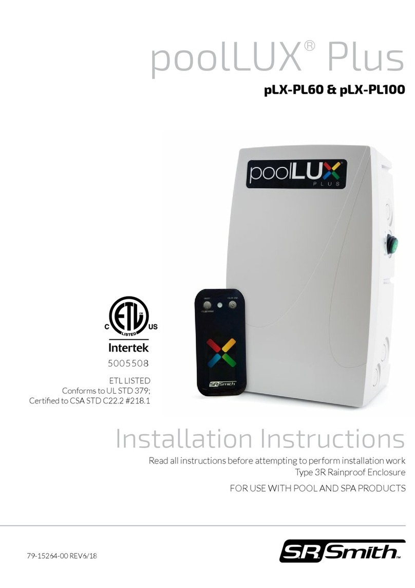
Pentair MICROBRITE User manual

EnglishEnglish Français Français Français Français FrançaisFrançais Español Deutsch Italiano Netherland
IMPORTANT SAFETY INSTRUCTIONS
READ AND FOLLOW ALL INSTRUCTIONS / SAVE THESE INSTRUCTIONS
MICROBRITE®
COLOR LED LIGHT FOR POOL AND SPA
INSTALLATION AND USER’S GUIDE
Compact LED light for 1.5" pool wall tting
620424-EU
G-INSB-MICRO-A

MicroBrite color led light for pool and spa Installation and User’s Guide
English
Pentair thanks you for placing your trust in the company and purchasing MICROBRITE®, the Compact LED light for 1.5"
pool wall tting. Please carefully read this user manual to fully benet from all of the functions of MICROBRITE®. Store
it carefully so that it can be consulted at any time.
Declaration of conformity
Directives – Harmonised standards
Pentair International Sarl - Avenue de Sévelin 20 - 1004 Lausanne - Switzerland
We declare, under our own responsibility, that the product meets the directives
SAFETY EN 60598-1 (2015) ; EN 60958-2-18 (1994) + A1
EMC EN 55015 / 2013 / AMD1: 2015 ; EN 61547 / 2009 ; EN 62493: 2015
EN 61000-3-2: 2014 ; EN 61000-3-3: 2013
PHOTOBIOLOGICAL SAFETY EN 62471 12/2008 ; IEC TR 62778 Edition 2 07/2014
MICROBRITE®:
620424
Other normative documents
2002/95/EC (RoHS)
2002/96/EC (WEEE)
Authorised person for technical documentation
Pentair International S.à.r.l
Avenue de Sévelin 20
1004 Lausanne - Switzerland
Lausanne, 2020 05 10
Jacques, Van Bouwel
Engineering Mgr
Product specications: 620424-EU
Operating temperature: 0° to 40° C
Consumption: 12 W
Maximum installation depth underwater: 2m
Operating hygrometry: 100% at 75° C
Weight (cable included): 1.2 kg
Power supply: 12 V ~, 50 Hz
Light (underwater use): IP 68
Waste treatment of electronic devices at the end of their service life:
The crossed-out bin placed on the main parts which make up the product indicates that it must not be disposed
of with household waste. It must be returned to an appropriate collection point for electronic device recycling
(information available from the local household waste collection service). This product contains potentially dan-
gerous substances which may have adverse effects on the environment and human health..
Customer Support: PISA, ITALY (8:30 A.M. to 4:30 P.M. CET) www.pentairpooleurope.com
- Warranty: 2 years
© 2020 Pentair International LLC, All rights reserved - The document is subject to change without notice
Trademarks and disclaimers: MicroBrite and Pentair are trademarks and/or registered trademarks of Pentair and/or its aliated
companies. Unless indicated otherwise, names and brands of others that may be used in this document are not used to indicate
an aliation or endorsement between the owners of these names and brands and Pentair. Those names and brands may be the
trademarks or the registered trademarks of these parties, or others.
COMPACT LED LIGHT FOR 1.5" POOL WALL FITTING
2

MicroBrite color led light for pool and spa Installation and User’s Guide
EnglishEnglish
If you have questions about ordering Pentair Aquatic Systems, (“Pentair”) replacement parts, and pool products,
please use the following contact information:
Customer Service
+39 050716166 / +39 050716169
orders.pooleu@pentair.com
poolemea@pentair.com
www.pentairpooleurope.com
Technical Support
e-mail: techsupport.poolemea@pentair.com
Hotline: +33 184280940
Table of contents
Important warning and safety instructions........................................... 04
Global presentation................................................................................................................. 05
Global wiring installation rules................................................................................. 05
Light installation......................................................................................................................... 06
Electrical connection.............................................................................................................10
Troubleshooting.............................................................................................................................15
Spare parts...........................................................................................................................................15
Maintenance........................................................................................................................................16
Technical drawings.................................................................................................................... 17
CUSTOMER SERVICE / TECHNICAL SUPPORT
3

MicroBrite color led light for pool and spa Installation and User’s Guide
English
IMPORTANT WARNING AND SAFETY INSTRUCTIONS
IMPORTANT NOTICE:
DANGER - SERIOUS BODILY INJURY OR DEATH
CAN RESULT IF THIS LIGHT IS NOT INSTALLED
AND USED CORRECTLY.
DANGER - INSTALLERS, POOL OPERATORS AND
POOL OWNERS MUST READ THESE WARNINGS
AND ALL INSTRUCTIONS BEFORE USING THE
POOL AND/OR SPA LIGHT.
Moststatesandlocalcodesregulate the con-
struction, installation, and operation of
public pools and spas, and the construction of residential pools
and spas. It is important to comply with these codes, many of
which directly regulate the installation and use of this product.
Consult your local building and health codes for more informa-
tion.
IMPORTANT NOTICE - Attention Installer: This Installation and
User’s Guide (“Guide”) contains important information about the
installation, operation and safe use of this underwater pool and
spa light. This Guide should be given to the owner and/or opera-
tor of this equipment. Before installing this product, read and
follow all warning notices and instructions in this Guide. Failure
to follow warnings and instructions can result in severe injury,
death, or property damage.
Please refer to www.pentairpooleurope.com for more informa-
tion related to this products.
DANGER - RISK OF ELECTRICAL SHOCK OR ELECTROCUTION:
UNDERWATER POOL LIGHTS REQUIRE HIGH VOLTAGE WHICH
CAN SHOCK, BURN, OR CAUSE DEATH.
Before working or servicing pool lights, always disconnect pow-
er to the pool and/or spa lights at the source circuit breaker.
Failure to do so could result in death or serious injury to ser-
vice person, pool users or others due to electric shock. When
installing and using this electrical equipment, basic safety pre-
cautions should always be followed.
ELECTRICAL WIRING RULES:
in accordance with the local regulation depending country :
A = ÔVE 8001-4-702 CZ = CSN 33 2000 7-702
D = OIN VDE 0100-702 E = UNE 20460-7-702 1993, RECBT ITC-BT-31 2002
EW = EVHS-HD 384-7-702 F = NF C15-100
GB = 6S7671:1992 H = MSZ 2364-702/1994/MSZ 10-553 1/1990
I = CEi 64-8/7 IRL = Wiring Rules + IS HD 384-7-702
LUX = 384-7.702 S2 M =MSA HD 384-7-702.S2
NL = NEN 1010-7-702 P = RSIUEE
PL = PN-IEC 60364-7-702:1999 SK = STN 33 2000-7-702
SLO = SIST HD 384-7-702.S2 TR = TS IEC 60364-7-702
All applicable local installation codes and ordinances must also
beadhered to.Improperinstallation will createan electrical haz-
ard which could result in death or serious injury to pool users,
installers or others due to electrical shock, and may also cause
damage to power source. Always disconnect the power to the
pool light at the circuit breaker before installing or removing
the light. Failure to do so could result in death or serious injury.
For countries in compliance with Interna-
tional Electrotechnical Commission (IEC)
-
son, in accordance with current IEC 364-7-702 and all applicable
local codes and ordinance. Improper installation will create an
electrical hazard, which could result in death or serious injury
to pool user, installer or other due to electrical shock and may
also cause damage to the property.
This product is intended for use in swimming
pool applications only.
POOL AND SPA FIXED LUMINARIES - Follow these guidelines
luminaries.
FOR LIGHT OPERATION, ONLY USE A SAFETY ISOLATION
TRANSFORMER COMPLIANT WITH NF EN 61558-2-6.
Note: Connect both wires to the corresponding circuit wires in
FIXED POOL AND SPA LUMINARIES SPECIFICATION: 12 VAC
50/60 Hz.
- IMPORTANT NOTICE - THE MICROBRITE COLOR AND WHITE
LED LIGHT IS A NON-SERVICEABLE LIGHT. THE COMPLETE
LIGHT ASSEMBLY MUST BE REPLACED.
- CAUTION - DO NOT INSTALL MICROBRITE COLOR AND WHITE
LED LIGHTS WITH DIMMER SWITCHES. USE OF DIMMER
SWITCHES WILL RESULT IN PERMANENT DAMAGE TO THE
LIGHT.
Connect the device to a differential inter-
rupter. If this system is used to control the
underwater lighting devices, a differential interrupter must be
installed upstream of these devices. Conductors downstream
of the differential interrupter shall not be located in ducts,
-
cept if the conductors are also protected by a differential inter-
rupter. Refer to valid local codes for more details.
4
MicroBrite color led light for pool and spa Installation and User’s Guide
EnglishEnglish
GLOBAL PRESENTATION
GLOBAL WIRING INSTALLATION RULES
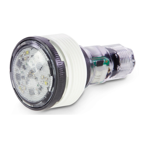
MICROBRITE® COLOR LED LIGHT OVERVIEW
This manual describes how to install, replace and operate the 12 VAC MicroBrite Color for pool and spa. The
MicroBrite Color light provides brilliant vivid multi-colors with spectacular effects for your pool. Choose one of the
dramatic underwater lighting effects for a spectacular effect in your pool and spa.
MICROBRITE® COLOR LED LIGHT WIRING INSTALLATION
1. Route the MicroBrite light power cord light
2. -
WARNING: Electrical wiring to the lighting must
be in accordance with the latest edition of the
Electrician Wiring Rules (see p4).
3. Connect the two (2) conductors to the corre-
4.
with water until the light is completely submerged.
Note: The MicroBrite color light should not be
powered for more than 30 seconds if is not sub-
merged in water.
5. Final check for proper MicroBrite light operation:
Switch on the main switch or circuit breaker to
the 12 VAC transformer and the switch that oper-
ates the MicroBrite light itself. The light should
illuminate when the 12 VAC power is applied. If not
recheck the installation steps.
5

MicroBrite color led light for pool and spa Installation and User’s Guide
English
6
INSTALLATION IN 1.5” WALL FITTING
The following describes how to install the MicroBrite
BEFORE STARTING: The following information
describes the tasks that must be completed by the
electrician before the light wall tting is installed. See
gure below.
Electrical wiring to the lighting must be
in accordance with the latest edition of
the Electrician Wiring Rules (voir p1).
lowvoltagetransformer(compliantwithNFEN61558-2-6)
must be located in the technical room.
LIGHT INSTALLATION
COMPATIBLE WALL FITTINGS
PENTAIR 86205100 HAYWARD SP1022
PENTAIR 542429 WATERWAY 215-9170B
PENTAIR 542402 WATERWAY 400-9150B
PENTAIR 542414 WATERWAY 215-9890B
PENTAIR 542411 (not recommended)) WATERWAY 400-9170B
PENTAIR 86205100 CMP CMP25550001060
PENTAIR 542405 CMP CMP25522100000
PENTAIR 542404 CMP CMP25550000000
10 cm min.
IP65 (ex : Pentair G-DECKBOX-1)
Waterproof connection
15 cm extra cord
To technical room

MicroBrite color led light for pool and spa Installation and User’s Guide
EnglishEnglish
7
WET CONDUIT INSTALLATION
Note: MicroBrite lights are shipped from the factory with the white threaded adaptor ring pre-installed onto the
body of the light. The male threads on the white threaded adaptor ring allow the light to be threaded into the female
To install the MicroBrite light wall tting into a concrete/vinyl pool:
1. To install a MicroBrite light, route the MicroBrite
light power cord light cable through the 1.5” wall
2. Wrap plumber’s thread sealant tape around the
male threads on the white threaded adaptor ring
on the light.
3. Pull the MicroBrite power cord through the conduit
between the body of the MicroBrite light and the
4. With the MicroBrite light in your hands, roll the
body of the light several turns counter-clockwise,
so that the cord of the MicroBrite light receives
several “pre-twists” in a counter-clockwise direc-
tion. Read Step 5 before continuing with Step 6.
5. Dry/Sealed Conduit Installation (use provided kit),
see page 7: If code requires an O-Ring to be in-
stalled on the light for a dry conduit installation,
install the O-Ring as described on page 9, then
continue with Step 6 below.
LIGHT INSTALLATION
By hand, turn light body
counter-clockwise to twist cord
Cord should be twisted counter-clockwise
Wrap threaded sealant tape
around the adaptor
1.5” Standard
wall tting

MicroBrite color led light for pool and spa Installation and User’s Guide
English
8
6.
7. Place Microbrite light installation tool (P/N
602158Z) over the front of the light while turning
the tool and light clockwise. Note: If the light does
not turn smoothly, pull the light slightly out and be
sure that it’s seated properly and the wall tting is
free of debris, then reinstall the light.
8. Turn the light clockwise while threading it into the
9.
10. Note: Once the light is tightly installed remove the
tool be sure the light cannot be unscrewed using
your ngers. The light should be secured in place
so that it can only be removed by using the light
installation tool.
LIGHT INSTALLATION
Insert adaptor male thread
adaptor ring into female
thread of wall tting. By hand
then turn light clockwise.
Cord will un-twist
as light is turned
clockwise into tting
Installation tool
1.5" Standard wall tting
Light cable to junction box

MicroBrite color led light for pool and spa Installation and User’s Guide
EnglishEnglish
9
DRY/SEALED CONDUIT INSTALLATION (USE PROVIDED KIT)
1. Note: The the pool water level must be below the
will be installed.
2. Unscrew the adaptor from the body of the light
and remove it along the 3m cord.
3. Pass the 3m cord inside the O-Ring.
4. Place the O-Ring behind the lens body.
5. Apply the provided lubricant on the O-Ring.
6. Pass the 3m cord inside the adaptor.
7. Place back the adaptor on the body of the light.
8. Resume the installation process at Step 1 (see
page 7).
LIGHT INSTALLATION
Install O-Ring then apply provided
lubricant to seal tting and conduit
from water entry
Adaptator
Adaptator
(nal location) Adaptator
O-Ring
(nal location)
O-Ring
1.5" Standard wall tting

MicroBrite color led light for pool and spa Installation and User’s Guide
English
10
ELECTRICAL CONNECTION
EXTERNAL SAFETY ISOLATION TRANSFORMER :
Using an External Safety Isolation Transformer for Multiple 12 VAC MicroBrite Lights
When using multiple MicroBrite 12 VAC ~ lights on a 100 Watt safety isolation transformer, it is recommended that
Maximum Wattage using multiple color (with a 300 Watt isolation transformer).
IMPORTANT! When using multiple 12 VAC Pentair pool and spa lights the total allowable light wattage should not
exceed 80% of rated value.
The individual light wattage is as follows:
• One MicroBrite Color Pool LED light is 12 Watts
• One IntelliBrite-e Pool Color LED light is 40 Watts
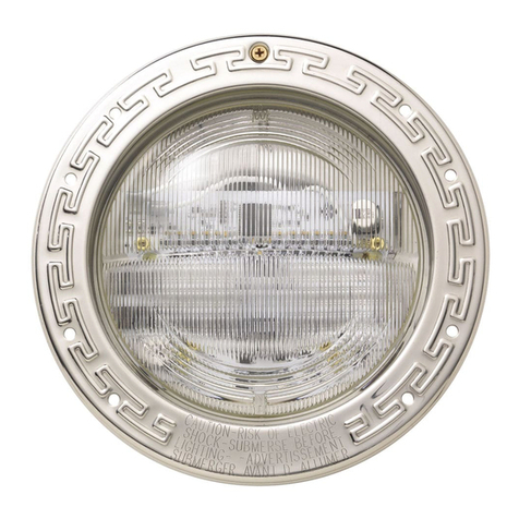
• One IntelliBrite-PAR56 Color LED light is 40 Watts
• -
nected on a 100W transformer.
• Up to twenty (20) MicroBrite 12 V AC lights can be
connected on a 300W transformer.
Powering on the MicroBrite color lights
When the MicroBrite color light is powered on, the previously selected color is displayed, unless the HOLD or
RECALL feature was previously enabled.
Note:
saved will be displayed.
12 V
AC ~
230 V
AC ~
2A
2A
Transformer compliant with NF EN 61558-2-6
Junction box
Wire connectors

MicroBrite color led light for pool and spa Installation and User’s Guide
EnglishEnglish
11
OPERATING MICROBRITE® COLOR LED LIGHT USING A WALL SWITCH
MicroBrite color lights can be controlled using a standard
wall-mount light switch (or by the IntelliBrite® Controller,
see page 12). Multiple MicroBrite color lights can be con-
single switch so that all lights can be switched on and off
together. MicroBrite color lights are controlled by cycling
AC power to the 12 VAC transformer from a standard wall
number of times, the light activates one of the seven
“Recall” feature.
Note-
nected to a 100W transformer
SELECTING A MICROBRITE COLOR LIGHT SHOW MODE OR FIXED COLOR USING
A WALL SWITCH
MicroBrite color lights are compatible with IntelliBrite® Color Light shows and can be synchronized with IntelliBrite
color lights. First switch power on to the light. A white light will momentarily illuminate, followed by the previously
of times.
Each number (1-12) shown below corresponds to the number of times to power-cycle the switch to activate a color
on page 10.
1. SAm Mode: Cycles through white, magenta, blue
and green colors (emulates the SAm color changing
light).
2. Party Mode: Rapid color changing building energy
3. Romance Mode: Slow color transitions creating a
mesmerizing and calming effect.
4. Caribbean Mode: Transitions between a variety of
blues and greens.
5. American Mode: Red, white and blue transition.
6. California Sunset Mode: Dramatic transitions of or-
ange, red and magenta tones.
7. Royal Mode: Richer, deeper color tones.
8. Blue:
9. Green:
10. Red:
11. White:
12. Magenta
13. Hold: Save the current color effect during a color
light show.
14. Recall: Activate the last saved color effect.
Example
switching process, no illumination will occur, then a white light will momentarily illuminate.
During the off/on switching process, before the selected color is displayed, no illumination will
occur. This operating mode is normal during the switching process. During this period the pool and
spa will be dark and precautions should be taken to avoid unforeseen accidents. Failure to observe this warning
may result in serious injury or death to pool and spa users.
ELECTRICAL CONNECTION
12 V
AC ~
230 V
AC ~
2A
2A
NEUTRAL (N)
PHASE(L)
Transformer compliant with NF EN 61558-2-6
Interrupteur Wire connectors
Junction box

MicroBrite color led light for pool and spa Installation and User’s Guide
English
12
ELECTRICAL CONNECTION
OPERATING MICROBRITE® COLOR LED LIGHT USING AN
INTELLIBRITE® CONTROLLER
Wiring MicroBrite Color LED Lights to IntelliBrite Controller and 300 Watt
Transformer
The following diagram shows how to connect MicroBrite Lights to an IntelliBrite
Controller using a 300 Watt transformer.
Selecting color and chow modes using an IntelliBrite
Controller
The MicroBrite color light can be controlled with the
IntelliBrite Controller (p/n 620139, sold separately). The
IntelliBrite® Controller provides complete control of your
MicroBrite color lights. Just dial in any one of the pre-
Using the IntelliBrite Controller:
MicroBrite color lights are compatible with IntelliBrite
colors and shows and can be synchronized with Intel-
liBrite color lights and landscape lights. To select a
dial so that it points to the desired selection. The color
mode selections start in a clockwise direction from the
9 o’clock position.
Hold and Recall Feature
• Hold button/LED: Press this button (LED on) to
capture and save a color effect while displaying
one of the light show modes. When the button is
pressed, the LED will be on, indicating that the
color effect is captured.
• Recall Button/LED: Use this button (LED on) to
activate the last saved color effect. When the but-
ton is pressed, the LED will be on, indicating that
the color effect is being displayed.
IntelliBrite Controller
12 V AC ~
230 V AC ~
2A
2A
230 V AC ~
Transformer compliant with
NF EN 61558-2-6
Junction box
Wire connectors
Wire
connectors
Wall Outlet

MicroBrite color led light for pool and spa Installation and User’s Guide
EnglishEnglish
13
OPERATING MICROBRITE® COLOR LED LIGHT USING
A CONTROLBRITE®
Refer to ControlBrite’s user manual for wiring.
Selecting color and show modes using a ControlBrite®
The MicroBrite color light can be controlled with the
ControlBrite (p/n CTRB-1010, sold separately). The
ControlBrite provides complete control of your Micro-
Brite color lights. Just press remote control buttons to
connected to individual or multiple 12 VAC transformers
• Use the ON/OFF key on the remote control or main
unit to switch the lights on or off.
• Use the >> or << key (remote or main unit) to
take a few seconds for the new scheme to become
active.
colors to sequences using the II> key.
Hold and Recall:
press the II> key on the remote control twice with a 1
sec interval. This function only works with one of the
sequences running. The saved color can be activated
ELECTRICAL CONNECTION
ON / OFF
Mode selector:
• 1 push =
• 2 pushes = save actual
(sequence mode only)
Next
color scheme
Previous
color scheme

MicroBrite color led light for pool and spa Installation and User’s Guide
English
14
ELECTRICAL CONNECTION
OPERATING MICROBRITE LIGHTS USING AN AUTOMATION SYSTEM
MicroBrite color lights can also be automatically controlled using the Pentair
IntelliPool, Maestro or Speedeo.
Refer to the automation device user manual for wiring.
Selecting color and show modes using an IntelliPool, a Maestro or a Speedeo automation device.
FOR INTELLIPOOL AND MAESTRO:
The MicroBrite Color light can be controlled with the
IntelliPool (p/n INTP-1010) or either the Maestro (p/n
SB-PF-ENS-002D) sold separately. The IntelliPool /
Maestro provides complete control of your MicroBrite
color lights:
• directly on the Control Center, by selecting light-
ing menu / color mode / mono or party ...
• on the App by selecting color mode in Lighting
window.
• on the IntelliPool / Maestro server by select-
ing color mode in Lighting window. Previously,
“IntelliBrite” and then save.
FOR SPEEDEO:
The MicroBrite Color light can be controlled with the
Speedeo (p/n SB-PF-SPO-003C, sold separately). The
Speedeo provides complete control of your MicroBrite
color lights directly on the Speedeo itself, by:
• Starting the secured Install menu (from the main
menu, simultaneously hold down Esc and Valid for
3 secs. A star appears in the top right corner of the
home screen).
• On the Inlets / E1 sub-menu, selecting LIGHTING
to indicate that a dry contact has been connected
to the corresponding inlet.
• For MicroBrite and other LED lights with colours
that may change with impulses, on the Home
menu, selecting Lighting and validating the cho-
sen light programme type (color mode / mono or
party ...).
230 V AC ~
230 V ~ 10A
2A
2A
12 V AC ~
An outlet is a dry contact and
does not supply any voltage. Junction box
Wire connectors

MicroBrite color led light for pool and spa Installation and User’s Guide
EnglishEnglish
15
Troubleshooting (MicroBrite lights)
Light does not function properly: Be sure that there is
12 VAC power applied to the light.
Troubleshooting (IntelliBrite Controller)
the AC power switch. The IntelliBrite Controller has
allowable wattage or the output is shorted out.
1. Switch off the IntelliBrite Controller OFF. Remove
2. Press the IntelliBrite Controller power switch to
power on the unit.
MICROBRITE® COLOR AND WHITE LED LIGHTS -
PARTS LIST:
Part No. Description
620424-EU MicroBrite Color Light 12 VAC -
3 meter cord
620428-EU MicroBrite White Light 12 VAC -
3 meter cord
620457-EU MicroBrite Warm White Light 12 VAC -
3 meter cord
MICROBRITE COLOR AND WHITE LED LIGHTS-
REPLACEMENT KITS
Part No. Description
620460 MicroBrite Light Adaptor
(replacement)
602158Z Installation Tool (replacement)
620463 Conduit Seal O-Ring (replacement)
TROUBLESHOOTING
SPARE PARTS

MicroBrite color led light for pool and spa Installation and User’s Guide
English
16
MAINTENANCE
REPLACING THE MICROBRITE® COLOR LED LIGHT ASSEMBLY
(IN AN EXISTING POOL OR SPA)
ELECTRICAL WIRING TO THE LIGHTING
MUST BE IN ACCORDANCE WITH THE
LATEST EDITION OF THE ELECTRICIAN WIRING RULES
(SEE P4).
IMPORTANT NOTICE: THE MICROBRITE COLOR LED
LIGHT IS A NON-SERVICEABLE LIGHT. THE COMPLETE
LIGHT ASSEMBLY MUST BE REPLACED.
VERIFYTHAT THEPOOLANDSPAMEETS
THE REQUIREMENTS OF THE CURRENT
LOCAL REGULATION APPLICABLE. A LICENSED OR CER-
TIFIED ELECTRICIAN MUST INSTALL THE ELECTRICAL
SYSTEM TO MEET OR EXCEED THOSE REQUIREMENTS
BEFORE THE UNDERWATER LIGHT IS INSTALLED.
IMPORTANT NOTICE: The following removal and installa-
tion instructions describe how to remove and install the
MicroBrite light assembly.
Failure to bring the pool or spa’s electrical system up to code requirements before installing the underwater light
will create an electrical hazard which could result in death or serious injury to pool users, installers, or others due
to electrical shock, and may also cause damage to property.
1. Switch off electrical switch or circuit breaker at
the source.
2.
pulling the replacement light power cord through
3. Remove the MicroBrite light assembly from the
pool or spa water: Using the provided installa-
tion tool (P/N 602158Z), rotate the light assembly
counter-clockwise ¹/of a turn to release the light
4. Slowly pull the light and attached power cord (with
-
ting and place the light on the deck.
5.
6.
for light installation instructions.
7. Connect the two (2) conductors to the corre-
page 4 and following for light wiring instructions.
8. -
tions.

MicroBrite color led light for pool and spa Installation and User’s Guide
EnglishEnglish
17
TECHNICAL DRAWINGS
MICROBRITE® COLOR LED LIGHT DIMENSIONS
O-Ring
Installation tool MicroBrite light adaptor
76 mm (3.0”)
ø 46.2 mm (1.82”)
ø 46.2 mm (1.82”)
12 mm (0.5”)
FITS 1-1/2”
NPT & NPS
THREADS
INSTALLATION TOOL INSTALLATION TOOL
SECTION VIEW
THREADED ADAPTER

PENTAIR INTERNATIONAL LLC,
Av. de Sévelin 18, CH-1004 - LAUSANNE, Switzerland
WWW.PENTAIR.COM
Third party registered and unregistered trademarks and logos are the property of their respective owners. Because we are
Pentair is an equal opportunity employer.
© 2020 Pentair. All rights reserved. This document is subject to change without notice.
P/N 8151696
10 / May / 2020
Manuel d’installation et d’utilisation du projecteur LED pour traversée de paroi 1.5’’
Other manuals for MICROBRITE
2
This manual suits for next models
1
Table of contents
Other Pentair Swimming Pool Lighting manuals

Pentair
Pentair JB 750 User manual

Pentair
Pentair INTELLIBRITE 5G User manual

Pentair
Pentair COLORVISION User manual

Pentair
Pentair INTELLIBRITE 5G User manual

Pentair
Pentair AQUALUMIN III User manual

Pentair
Pentair MAGICSTREAM LAMINAR User manual

Pentair
Pentair AMERBRITE Operation manual

Pentair
Pentair INTELLIBRITE 5G LED LIGHT User manual

Pentair
Pentair MICROBRITE User manual

Pentair
Pentair Amerlite Reference guide