Pfannenberg PMF 2015-M Product guide

085501847c 11516-35c 1
Betriebs- und Montageanleitung für Rundum-Blitzleuchte Typ PMF 2015-M
Operating and Assembly Instructions f. All-Round Flashlight Type PMF 2015-M
Instruction de service et de montage pour feu tournant à lampe à éclats de type
PMF 2015-M
1. Anwendung und Funktion
Bei der PMF 2015-M handelt es sich um eine Rundum-Blitzleuchte zur optischen Signalisierung von Gefahrzuständen z.B. an
Bahnübergängen. Es können optische Warn- und Notsignale bis zu einer maximalen Einzelblitzenergie von 7 Joule erzeugt
werden. Durch eine als Fresnell-Linse ausgebildete Haube und einer speziellen XENON-Blitzröhre wird eine gute Bündelung
des Lichtes in horizontaler Ebene erreicht. Dies ermöglicht eine sehr gute Erkennbarkeit über große Entfernungen bei kleiner
Leistungsaufnahme. Die Rundum-Blitzleuchten sind für den Einsatz sowohl in Gebäuden als auch im Freien konzipiert.
Schlagregen und Betauung führen bei den Geräten zu keiner Schädigung. Innere Betauung ist zulässig.
Die Funktion der Blitzleuchte wird intern über einen optischen Sensor und eine Auswerteschaltung überwacht. Beide Teilsys-
teme (Blitzleuchte u. Überwachungseinheit) haben separate Betriebsspannungsanschlüsse. Nach Anlegen der Betriebsspan-
nung für beide Teilsysteme zieht ein Sicherheitsrelais mit zwangsgeführten Kontakten an. Die Relaiskontakte sind als externe
Schnittstelle zu weiteren überwachenden Einheiten zu nutzen.
Nach Ausfall der Betriebsspannung fällt das Relais sofort ab. Bleibt nach dem Einschalten der Leuchte die regelmäßige Blitz-
folge aus, fällt das Relais nach 1,5 –3,5 Sekunden ab. Treten erneut Lichtblitze auf, wird über einen Integrator das Auswer-
terelais wieder freigegeben.
1. Application and Function
The PMF 2015-M is an all-round flashlight for the optical signalling of dangers, for example at level crossings. Optical alarm
and emergency signals can be generated with maximum single-flash energy of 7 Joules. A favourable bundling of the light on
a horizontal level is achieved by a Fresnel lens-shaped hood and a special XENON flash tube. This allows for a very good
recognisibility over large distances with a small power input. The all-round flashlights are designed for use inside buildings and
outside. Heavy rain and dew precipitation do not damage the equipment in any way. Condensation is allowed on the inside.
The function of the flashlight is internally monitored by an optical sensor and an analysing device. Both part systems (flashlight
and monitoring unit) have separate operating voltage connections. After connecting to the operating voltage for both part sys-
tems a safety relay with purpose driven contacts is switched on. The relay contacts are to be used as external interfaces with
other monitoring units.
After disconnection from the operating voltage the relay is immediately switched off. If, after turning on the light, the regular
flash remains out then the relay switches off after 1.5 to 3.5 seconds. If new light flashes arise, then the analysing relay will
again be released by an integrator.
1. Application et fonction
PMF 2015-M est un feu tournant à lampe à éclats pour signalisation optique des situations dangereuses, telles que les pas-
sages à niveau, par exemple. Ils produisent des signaux optiques d'avertissement et de secours jusqu'à une énergie d'éclat
lumineux maximale de 7 joules. Une lanterne conçue sous la forme d'une lentille en échelon et un tube à éclat lumineux spé-
cial XENON permettent d'obtenir une bonne focalisation de la lumière au niveau horizontal. Ceci permet une bonne perceptibi-
lité à de grandes distances pour une faible puissance consommée. Les feux tournants à lampe à éclats sont conçus pour être
utilisés aussi bien dans les bâtiments qu'à l'extérieur. La pluie battante et la rosée ne peuvent pas endommagées les appa-
reils. La rosée interne est permise.
La fonction de la lampe à éclats est surveillée en interne par un capteur optique et un couplage d'évaluation. Les deux sous-
systèmes (lampe à éclats et unité de surveillance) ont des raccordements distincts à la tension de service. Après la mise sous
tension de service des deux sous-systèmes, un relais de sécurité avec des contacts à actionnement forcé se ferme. Les con-
tacts de relais doivent être utilisés comme interface externe pour d'autres unités de surveillance.
Dès la mise hors tension, le relais se détache immédiatement. S’il n’y pas de séquence d’éclair régulière après la fermeture
du circuit de la lampe, le relais tombe après 1,5 à 3,5 secondes. Si des éclairs apparaissent de nouveau, le relais d'évaluation
est libéré à nouveau sur un intégrateur.
2. Montage
Die Befestigungsbohrungen können dem Bohrbild entnommen werden.
Die Leitungsdurchführung erfolgt über eine Kabelverschraubung M20x1,5,
geeignet für Leitungsdurchmesser von 6,5 mm –13,5 mm.
The attachment drill holes can be seen in the drill diagram. There is a
M20x1.5 screw joint for the cable fittings, suitable for cable diameters of
between 6.5 and 13.5 mm.
On trouvera les perçages de fixation sur la configuration de perçage. Le
passage de la ligne a lieu par un adaptateur vissable pour câble M20x1,5
approprié pour le diamètre de ligne de 6,5 mm –13,5 mm.
170.5
90
50
75 4
M20x1,5
Ø6.5
50
45
085501847c 11516-35c 2
3. Inbetriebnahme
Nach Entfernen der seitlichen Sicherungsschrauben kann das Gehäuse durch Abnehmen der Haube geöffnet werden. Die
Anschlussklemme ist damit frei zugänglich. Vor dem Öffnen des Gehäuses sind folgende Sicherheitshinweise zu beachten.
Der elektrische Anschluss darf nur von hierfür autorisierten Personen durchgeführt werden!
Vor dem Öffnen des Gehäuses ist sicherzustellen, dass die Leuchte nicht unter Spannung steht und mindestens
10 Minuten spannungsfrei geschaltet ist!
Achtung, falsche Betriebsspannungen können zu Störungen oder zur Zerstörung des Gerätes führen!
Nach Abschluss der Arbeiten und vor dem Einschalten der Rundum-Blitzleuchte ist das Gehäuse zu verschließen.
Das Gerät ist mit einem Verpolungsschutz ausgestattet. Keine Funktion bei Verpolung der Anschlüsse!
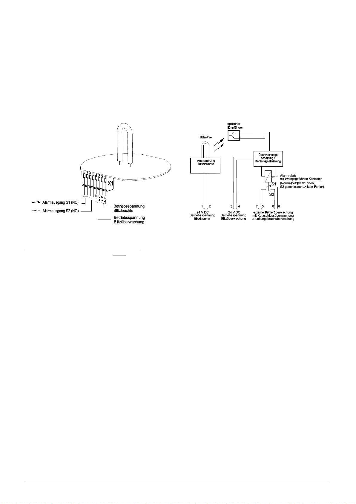
Der Betriebsspannungsanschluss von Blitzleuchte und Überwachungseinheit sowie der Anschluss der Alarmausgänge erfolgt
nach dem Öffnen des Gehäuses über die frontseitig zugängliche und gekennzeichnete Klemme. Stellen Sie sicher, dass das
Gerät nur mit der vorgeschriebenen Spannung betrieben wird.
Abb. 1 Abb. 2
Sicherheitsbezogene Anwendungsbedingungen
Um höchste Sicherheit zu erlangen, muss ein übergeordnetes System vorhanden sein, dass in der Lage ist, eine Fehleranaly-
se anhand der Alarmausgänge S1 u. S2 in Verbindung mit dem Betriebszustand der Leuchte durchzuführen. Folgende Ab-
hängigkeiten zwischen Betriebszustand und Alarmausgänge sind dabei möglich:
1. Ein Einschalten der Versorgungsspannung der Blitzleuchte (Signalgebung) und der Blitzüberwachung hat im fehlerfreien
Zustand ein Wechsel der Relaiskontakte S1 u. S2 zur Folge. Erfolgt der Wechsel nicht, so ist ein Fehler an der Blitz-
leuchte, der optischen Überwachungseinheit oder den Anschlussleitungen aufgetreten (siehe hierzu auch das Zeitdia-
gramm der Alarmsignalleitungen, Abb. 3). Dieses trifft ebenfalls auf das Ausschalten der Versorgungsspannungen zu.
2. Tritt während der Betriebsphase der Leuchte der Fall ein, dass die Blitze ausbleiben, so findet innerhalb von
1,5 –3,5 Sekunden ein Wechsel der Alarmkontakte statt.
3. Leitungsbruch oder –kurzschluss an den Alarmausgängen kann aufgrund der zwangsgeführten Relaiskontakte gemäß
Abb. 3 sofort detektiert werden.
4. Bei „festgebrannten“ Relaiskontakten und gleichzeitigem weiteren Fehler der Leuchte in der Betriebsphase kann der
Fehler nicht sofort erkannt werden, da die Kontakte in diesem Fall nicht wechseln. Dieser Fehler wird spätestens beim
Ausschalten der Versorgungsspannung erkannt, da zu diesem Zeitpunkt ein Wechseln der Alarmkontakte erwartet wird.
Strom- und spannungsbegrenzende Maßnahmen müssen im überwachenden System sowohl für die Versorgung des Systems
als auch für die Alarmschnittstelle implementiert werden. Damit kann sichergestellt werden, dass die Kontakttemperaturen die
Verschweißtemperaturen der Alarmkontakte nicht erreichen (Verhinderung des unter 4. beschriebenen Fehlerbildes).
Um alle Fehler der Blitzleuchte und der Überwachungseinheit sicher detektieren zu können, ist es ist notwendig, einen Sys-
temtest in periodischen Abständen durchzuführen. Der Systemtest kann wie folgt ausgeführt werden:
Einschalten der Spannungsversorgung der Blitzüberwachung bei nichteingeschalteter Blitzleuchte
Überprüfung, ob Alarmrelais für 1,5 –3,5 sec. anzieht,
Überprüfung, ob Alarmrelais danach ordnungsgemäß abfällt (Fehler erkannt), siehe auch Abb. 3, zweites Diagramm.
In welchen Abständen dabei ein Systemtest zu erfolgen hat, ist abhängig von der endgültigen Applikation in der die
PMF 2015-M eingebunden ist. Die anlagenspezifischen Prüfintervalle müssen in den jeweiligen Sicherheitsnachweisen defi-
niert werden. Bei Einsatz der Leuchte als Blinksignal an Bahnübergängen (nur für die Schweiz) sind die Anforderungen der
Typenzulassung 401 11 01 zu berücksichtigen.

085501847c 11516-35c 3
3. Taking into operation
After the removal of the lateral safety screws, the casing can be opened by removing the hood. The connection clamp is there-
fore freely accessible. The following safety references are to be given consideration before opening the casing.
The electrical connection must only be carried out by such persons as are authorised to do so! It must be ensured
before opening the casing that the light is not under voltage and has been voltage-free for at least 10 minutes!
Attention, false operating voltages may lead to malfunctions or the destruction of the device!
The casing must be closed after the completion of the work and before switching on the all-round
flashlight.
The device is provided with a reverse polarity protection. No function when polarity is reversed!
The operating voltage connection for the flashlight and monitoring unit as well as the connection for the alarm connector
is made after opening the housing by the forward accessible and labelled clamp. Ensure that the apparatus is only oper-
ating with the prescribed voltage.
Operating voltage
Flash monitoring
Operating voltage
flashlight
(normal operating S1 open,
alarm relay with
S2 closed -> no fault)
purpose driven contact
and connection break monitoring
with short circuit monitoring
extenal fault monitoring
operating voltage
flashlight
24 V DC
1 2
control
flash light
flash tube
S1
operating voltage
flash monitoring
24 V DC
3 4 7 5 6 8
S2
optical receiver
fault signalling
monitoring switch/
Fig. 1 Fig. 2
Safety related application conditions
To achieve a high level of safety a superior system must be available, which is in a position to implement a fault analysis on
the basis of the alarm connector S1 and S2 in connection with the operating state of the lights. The following connections
between the operating state and alarm connection are thus possible:
1. Turning on the supply voltage of the flashlight (signal giving) and the flash monitoring results, in a fault free state, in an
exchange of the relay contacts S1 and S2. If the exchange does not take place then there is a fault as regards the flash-
light, the optical monitoring unit or the connection connector (also see for this the time diagram of the alarm signal trans-
mission, fig. 3). This likewise results in the turning off of the supply voltages.
2. If, during the operating phase of the lights, flashes fail to appear then within 1.5 to 3.5 seconds an exchange of the alarm
contact takes place.
3. A break in connection or a short circuit in the alarm connection can be immediately detected due to the purpose driven
relay contact in accordance with fig. 3.
4. In case of ‘burnt’ relay contacts and at the same time other faults of the lights in the operating phase the faults can be
recognized immediately as the contacts in this case do not change. This fault is recognized at the latest when disconnect-
ing the supply voltage as, by this time, a change of the alarm contact is expected.
Electricity and voltage limiting measures must be implemented in the monitoring system for the supply of the system as well as
for the alarm interface. In this way it can be ensured that the contact temperatures and the fuse temperatures of the alarm
contacts are not reached. (Prevention of the fault picture shown in 4).
In order to be able to definitely detect all the faults of the flashlight and the monitoring unit a system test must be carried out at
regular intervals. The system test can be carried out as follows:
Switching on of the supply voltage of the flash monitoring with a non-turned on flashlight.
Verification of whether alarm relay turns on after 1.5 –3.5 sec.,
Verification of whether alarm relay afterwards turns off accordingly (fault recognized), see also fig. 3, second diagram.
In which conditions a system test should be carried out depends on the definitive application in which the PMF 2015-M is in-
volved. The unit specific test intervals must be defined in the safety audits. When using the flashlight as a blinking alarm at
railroad crossings (valid only for Swiss) the requirements of the type approval 401 11 01 are to be considered.

085501847c 11516-35c 4
3. Mise en service
Après avoir enlevé les vis de sécurité latérales, le boîtier peut être ouvert, en retirant la lanterne. La borne de branchement est
ainsi librement accessible. Avant l'ouverture du boîtier, les consignes de sécurité suivantes doivent être respectées.
Le branchement électrique ne doit être exécuté que par des personnes autorisées pour cela!
Avant l'ouverture du boîtier, il faut s'assurer que la lampe n'est pas sous tension et qu'elle est sans tension depuis au
moins 10 minutes!
Attention, les tensions de service incorrectes peuvent conduire à des perturbations ou destruction de l'appareil!
Il faut refermer le boîtier à la fin des travaux, et avant la remise en circuit du feu tournant à lampe à éclats.
La lampe est équipée avec une protection contre l'inversion de polarité. Pas de fonction en cas de l‘inversion de la polarité!
Le raccordement à la tension de service de la lampe à éclats et de l’unité de surveillance ainsi que le raccordement des so r-
ties d'alarme s'effectuent après l'ouverture du boîtier au-dessus du collier portant une marque et accessible par la face avant.
Assurez-vous que l'appareil est utilisé uniquement à la tension prescrite.
24V DC
Surveillance externe d'erreur
avec surveillance du court circuit
et de la rupture de la ligne
à actionnement forcé
S2 fermé -> Aucune erreur)
Relais d'alarme avec contacts
(Utilisation normale S1 offen,
1
24 V DC
2
tube à éclats
Contrôle
lampe à éclats
24 V DC
3 4 7 5 6 8
S1
S2
Récepteur
optique
Fig. 1 Fig. 2
Conditions d'application en sécurité
Pour atteindre un niveau de sécurité maximale, un système superordonné doit exister de sorte qu’une analyse d’erreurs
puisse être mise en œuvre au moyen des sorties d'alarme S1 et S2 en relation avec l'état de la lampe. Les situations sui-
vantes entre un état de la lampe et les sorties d'alarme sont possibles :
1. En mode sans erreur, une mise sous tension de la lampe à éclats (signalisation) et de la surveillance de l’éclat entraîne un
changement des contacts de relais S1 et S2. Si le changement n'a pas lieu, une erreur apparaît au niveau de la lampe à
éclats, de l'unité de surveillance optique ou aux lignes de raccordement (consulter à ce sujet le diagramme temporel des
lignes du signal d'alarme, fig. 3). Cette situation s'applique également en cas de mise hors tension.
2. S’il n’y a pas d’éclats pendant la phase d’utilisation de la lampe, un changement des contacts d'alarme a alors lieu dans un
délai de 1,5 à 3,5 secondes.
3. Un court circuit ou une rupture de la ligne au niveau des sorties d'alarme peuvent être détectés immédiatement sur la base
des contacts de relais à actionnement forcé, conformément à la fig. 3.
4. Avec des contacts de relais « brûlés solidement » et simultanément, une autre erreur de la lampe dans la phase d'exploita-
tion ne peut pas être reconnue immédiatement, puisque les contacts dans ce cas ne changent pas. Cette erreur sera re-
connue plus tard lors de la mise sous tension, puisque le changement des contacts d'alarme est attendu à ce moment.
Les mesures des limites de courant et tension doivent être mises en œuvre dans le système de surveillance aussi bien pour
l'alimentation du système que pour l'interface d'alarme. De cette façon, il est certain que les températures de contact n'attei-
gnent pas les températures de soudage des contacts d'alarme (prévention à la 4ème image d'erreur décrite).
Pour pouvoir détecter de façon sûre toutes les erreurs de la lampe à éclairs et de l'unité de surveillance, il est nécessaire de
tester le système périodiquement. Le test du système peut être conduit de la manière suivante :
Mettre la surveillance d’éclair sous la tension réseau, tout en gardant la lampe hors tension.
S’assurer que le relais d'alarme se ferme dans un délai de 1,5 à 3,5 s.
Examiner ensuite si le relais d'alarme tombe de manière régulière (erreur reconnue), voir aussi la fig. 3, deuxième
diagramme.
Le choix des intervalles de test du système dépend de l’usage final auquel est destiné le PMF 2015-M. Les intervalles de test
propres au système doivent être spécifiés dans les certificats de sécurité respectifs. Si l'appareil est utilisé comme un signal
clignotant aux passages à niveau (Suisse uniquement), les exigences des approbations 401 11 01 doivent être respectées.

085501847c 11516-35c 5
Instant de mise hors tension
- PMF-M: defekt/ defect/ défectueux
- Überwachung i.O./ monitoring ok/
- PMF-M: i.O./ ok/ en bon état
Instant de mise sous tension
Phase inactive
1,5 - 3,5s
Betriebsphase/ Operating time/ Phase active
S1
S1
S2
S2
S2
S2
S1
S1
S1
S2
S2
S1
S1
S2
S2
S1
S1
S2
S2
S1
S1
S2
S2
S1
S1
S2
S2
S1
S1
S2
S2
S1
Surveillance en bon état
Surveillance en bon état
- Überwachung i.O./ monitoring ok/
- Überwachung i.O./ monitoring ok/
Surveillance en bon état
- PMF-M: i.O./ ok/ en bon état
- Leitungsbruch Pfad S2/ connection break path S2/
Rupture de la ligne à la voie S2
- Leitungsbruch Pfad S1/ connection break path S1/
- Überwachung i.O./ monitoring ok/
Surveillance en bon état
- PMF-M: i.O./ ok/ en bon état
Rupture de la ligne à la voie S1
- Kurzschluss Pfad S2/ short circuit path S2/
- Überwachung i.O./ monitoring ok/
Court-circuit sur la voie S2
Surveillance en bon état
- PMF-M: i.O./ ok/ en bon état
Court-circuit sur la voie S1
- PMF-M: i.O./ ok/ en bon état
Surveillance en bon état
- Überwachung i.O./ monitoring ok/
- Kurzschluss Pfad S1/ short circuit path S1/
Ausschaltzeitpunkt/ Turn-off time/
Einschaltzeitpunkt/ Turn-on time/
Ruhephase/ neutral time Ruhephase/ neutral time
Phase inactive
Abb. 3 - Zeitdiagramm der Alarmsignalleitungen
Fig. 3 - Time diagram of the alarm signal connections/ Diagramme temporel des lignes du signal d'alarme

085501847c 11516-35c 6
4. Instandhaltung
Pflege
Das Kunststoffgehäuse darf nur mit Wasser und einem Handspülmittel gereinigt werden. Keine Reinigungsmittel die kratzen
oder scheuern, kein Benzin und keine anderen Lösungsmittel verwenden.
Wartung
Die Rundum-Blitzleuchte ist wartungsfrei. Reparaturen sind grundsätzlich im Herstellerwerk auszuführen. Der Austausch von
Originalersatzteilen kann durch entsprechend qualifizierte Personen durchgeführt werden.
4. Maintenance
Care
The plastic casing must only be washed using water and a detergent which does not damage the hands. Do not use any de-
tergents which scratch or scrub, and do not use petrol or other solvents.
Maintenance
The all-round flashlight is maintenance-free. Repairs may only be carried out in the manufacturing plant. The exchange of
original spare parts can be implemented by persons with adequate suitable qualifications.
4. Entretien
Soins
Le boîtier en plastique ne doit être nettoyé qu'avec de l'eau et un produit à vaisselle. Ne pas utiliser de détergents qui grattent
ou récurent, ni d'essence ou de dissolvant.
Maintenance
Le feu tournant à lampe à éclats est sans maintenance. Les réparations doivent être exécutées, en principe, dans l'usine du
fabricant. L'échange des pièces originales peut être réalisé par des personnes qualifiées.
5. Technische Daten / Technical Data / Caractéristiques techniques
Bemessungsspannung
für
Blitzleuchte und
Überwachungseinheit
Rated voltage for
flashlight and
monitoring unit
Tension de service nominale
de la lampe à éclats et de
l’unité de surveillance
24V DC
Toleranz
Tolerance
Tolérance
18V ... 30 V
Stromaufnahme
Blitzleuchte
Current uptake:
flashlight
Courant nominal de la lampe à
éclats
0,65 A
Stromaufnahme
Überwachungseinheit
Current uptake:
monitoring unit
Courant nominal de l’unité de
surveillance
0,05 A
Alarmkontakt / Alarm contact / Contact d’alarme
Kontaktausführung
Contact execution
Mise en œuvre du contact
Zwangsgeführt/ Purpose driven/
Mise en œuvre forcée
Nennstrom
Nominal current
Courant nominal
6A
Nennspannung
Nominal voltage
Tension nominale
250V AC
Max. Schaltleistung AC
Max. breaking capacity AC
Capacité CA Max. des contacts
1500 VA
Empfohlene Minimallast
Recommended minimal
load
Charge minimale recomman-
dée
>50 mW
Haubenfarbe
Hood color
Couleur de lanterne
Rot/ red/ rouge
Blitzfolge
Flash sequence
Séquence d’éclairs
2-fach Blitz/ 2-fold flash/
2-fois éclair
Blitzfreqenz des
Hauptblitzes
Flash frequency of the
main flash
Fréquence de l’éclair principal
1 Hz
Blitzenergie des
Hauptblitzes
Flash energy of the
main flash
Énergie de clignotement de
l’éclair principal
7 Joule
Einschaltdauer
Duty cycle
durée de fonctionnement
100%
Betriebstemperatur
Operating temperature
Température de service
-30 °C ... +55°C
Lagertemperatur
Storage temperature
Température de stockage
-40°C ...+70°C
Relative Feuchte
relative Humidity
Humidité relative
90%
Schutzart
Protective system
Indice de protection
IP 55
Kabeleinführung
Cable gland
Entrée de câble
M20x1,5
für Leitungen, for cables/ pour lignes
6,5 mm ... 13,5 mm
Klemmbereich der
Anschlussklemme
Clamping range of the
connection clamp
Gamme du serrage
du collier de raccord
0,08 .. 2,5 mm²
Betriebsgebrauchslage
Operating position
Position d'utilisation industrielle
Senkrecht/ vertical/ verticalement
Betriebsbedingungen
Operating conditions
Conditions d'utilisation
für Außeneinsatz geeignet
suitable for field use
Adapté pour usage externe/
Schwellenwert
Blitzüberwachungs-
frequenz
Marginal value
flash monitoring frequency
Valeur seuil de la fréquence de
surveillance d’éclair
0,8 Hz (Blitzfrequenzen unterhalb dieser
Frequenz führen zu Fehlermeldung)
(Flash frequency below this frequency
leads to fault reporting)
(Les fréquences au-dessous de cette
valeur génèrent un message d'erreur)

085501847c 11516-35c 7
6. Normenkonformität
EN 50129 : 2003 Bahnanwendungen –Telekommunikationstechnik, Signaltechnik und Datenverarbei-
tungssysteme –sicherheitsrelevante elektronische Systeme für Signaltechnik
EN 12352 : 2000 Anlagen zur Verkehrssteuerung, Warn- und Sicherheitsleuchten
Klasse: L1 C rot F3 O3 M0 T1 S3
6. Standard conformity
EN 50129 : 2003 Railway applications –Telecommunications technology, signal technology and data pro-
cessing systems –safety related electronic systems for signalling
EN 12352 : 2000 Traffic control equipment, warning and safety light devices
Class: L1 C red F3 O3 M0 T1 S3
6. Conformité des normes
EN 50129 : 2003 Applications ferroviaires –Télécommunication, Signalisation et exploitation des données
–Systèmes électroniques de sécurité pour la signalisation
EN 12352 : 2000 Equipement de régulation du trafic, Feu de balisage et d’alerte
Classe: L1 C rouge F3 O3 M0 T1 S3
Wir haften nicht für Störungen oder Schäden, die durch Maßnahmen entstehen, die in der von uns gelieferten Inbetrieb-
nahmeanleitung nicht enthalten sind.
Ansonsten gelten die Allgemeinen Bedingungen für Lieferungen und Leistungen des Zentralverbandes der
Elektroindustrie (ZVEI), neueste Fassung.
We are not liable for malfunctions or damage which are caused by measures which are not contained in the commis-
sioning instructions which we provide.
The General Terms of Deliveries and Services of the Central Association of the German Electrical Industry (ZVEI) in
their latest version shall otherwise apply.
Nous ne répondons pas des perturbations ou dommages occasionnés par des mesures qui ne sont pas contenues dans
l'instruction de mise en service livrée avec l'appareil.
Sinon, on appliquera les conditions générales pour les fournitures et prestations de l'association centrale de l'électro-
industrie (ZVEI), dans sa dernière version.
Pfannenberg GmbH
Werner-Witt-Straße 1 ·D- 21035 Hamburg 08/2015
Tel.: +49/ (0)40/ 734 12-0 ·Fax: +49/ (0)40/ 734 12-101 Technische Änderungen, die dem Fortschritt dienen, vorbehalten.
technical.support @pfannenberg.com We reserve the right to make any technical alterations in the interests of improvement
http://www.pfannenberg.com Nous nous réservons le droit de modifier certaines des caractéristiques ci-dessus selon l'évolution des normes et des techniques.
085501847
Other Pfannenberg Lighting Equipment manuals

Pfannenberg
Pfannenberg PY L-S-TL User manual

Pfannenberg
Pfannenberg Quadro-LED HI Assembly instructions

Pfannenberg
Pfannenberg Quadro LED-TL User manual

Pfannenberg
Pfannenberg PY X-M-05 User manual

Pfannenberg
Pfannenberg ABL User manual

Pfannenberg
Pfannenberg Quadro LED-RGB-3G/3D User manual

Pfannenberg
Pfannenberg PY L-S User manual

Pfannenberg
Pfannenberg Quadro-LED HI User manual

Pfannenberg
Pfannenberg Quadro LED-RGB-3G/3D Original instructions

Pfannenberg
Pfannenberg Quadro-LED Flex-3G/3D User manual


