Pfannenberg PY L-S User manual

Betriebsanleitung PY L-S
03/2021 Seite 1 / 8 086200015b
de
en
fr
it
ru
Schutzvermerk nach DIN ISO 16016 beachten!
Originalsprache
Inhalt
1. Bestimmungsgemäße Verwendung ..........................................................................................................1
2. Lieferumfang................................................................................................................................................1
3. Abmessungen..............................................................................................................................................2
4. Technische Daten........................................................................................................................................2
4.1 Allgemein ....................................................................................................................................................2
4.2 Elektrische Kenndaten................................................................................................................................3
5. Zulassungen ................................................................................................................................................3
6. Inbetriebnahme............................................................................................................................................3
6.1 Sicherheitshinweise ....................................................................................................................................3
6.2 Elektrischer Anschluss................................................................................................................................4
7.1 Einstellung der Betriebsarten - Versionen mit Einzelfarben-LED (ohne externe Ansteuerung).........5
7.2 Einstellung der Betriebsarten - Versionen mit Multicolor-LED (RGBW) ...............................................5
7.2.1 ohne externe Ansteuerung ....................................................................................................................5
7.2.2 mit externer Ansteuerung ......................................................................................................................6
8. Option...........................................................................................................................................................6
9. Zubehör ........................................................................................................................................................7
10. Wartung, Service, Instandhaltung.............................................................................................................7
11. Außerbetriebnahme, Demontage und Entsorgung..................................................................................7
1. Bestimmungsgemäße Verwendung
LED-Leuchten der PYRA - Serie sind für die optische Signalisierung von z.B. Gefahrzuständen in Industrie,
Gewerbe und Gebäudebereichen bestimmt.
Die LED im Leuchtenteil kann in verschiedenen Betriebsarten betrieben werden, die mithilfe eines internen
Schalters eingestellt werden können.
Die Multicolor (RGBW)-Versionen bieten zusätzlich die Möglichkeit, den einzelnen Betriebsarten unterschiedli-
chen Farben zuzuordnen. Außerdem besteht bei diesen Versionen die Möglichkeit, über externe Ansteuerung
alternative Betriebsarten und Farben zu wählen.
Die Geräte nur in unbeschädigtem Zustand innerhalb der spezifizierten Kenndaten betreiben. Die Funktion des
Gerätes ist nur gewährleistet, wenn Ober- und Unterteil korrekt zusammengefügt sind.
Die Geräte sind für den Einsatz im Innen- und Außenbereich geeignet und nur für die ortsfeste Montage be-
stimmt.
2. Lieferumfang
Der Lieferumfang besteht aus:
1x Signalgerät
1x Membrannippel M20
(Option: Kabelverschraubung/ M12-Stecker)
1x Kurzanleitung

Betriebsanleitung PY L-S
03/2021 Seite 2 / 7 086200015b
de
3. Abmessungen
M20-Ausbruch vorbereitet
Bohrbild im Inneren des Gehäuses
4. Technische Daten
4.1 Allgemein
PY L-S
Lichtstärke 76 cd (klar)
Leuchtmittel 1x Hochleistungs-LED
Farben RGBW-LED
blau, rot, grün, gelb
zusätzlich über externe Ansteuerung: weiß
Einschaltdauer 100%
Anschlussklemmen 0,14 - 2,5mm² feindrähtig / AWG24 - AWG 14
Schutzart IP 66 (EN 60529), Type 4 & 4x
Schlagfestigkeit IK08 (EN 50102)
Schutzklasse II
Betriebstemperatur -40 °C…+55 °C
Lagertemperatur -40 °C…+70 °C
Max. rel. Luftfeuchte 90%
Kabeleinführung 4x M20 vorgeprägt
Dichtbereich der
Durchführungstülle
7 – 13 mm Bei Verwendung von Kabeldurchmessern < 7 mm eine Kabel-
verschraubung mit ausreichender Schutzart vorsehen
Gehäusematerial PC/ ABS Blend
Haubenmaterial PC
Einbaulage beliebig
Haubenfarben
klar, weiß, gelb, orange, rot, grün, blau
RGBW-Version: weiß
M20-Ausbruch vorbereitet

Betriebsanleitung PY L-S
03/2021 Seite 3 / 7 086200015b
de
4.2 Elektrische Kenndaten
Bemessungsspan-
nungsbereich 12 – 48V DC 24 V AC
50/ 60 Hz
115 - 230 V AC
50/ 60 Hz
120V DC
Arbeitsspannungsbe-
reich 10 – 60 V DC 21,6 – 26,4
V AC
90 – 265 V AC
108 -132V DC
Bemessungsstrom-
aufnahme (max)
12 V DC
24 V DC
48 V DC
167 mA
120V DC
115V AC
230V AC
275 mA 120 mA 65 mA 74,4 mA 51 mA 36 mA
Leistungsaufnahme
(max) 3,3 W 2,9 W 3,1 W 4 VA 2,93 W 5,9 VA 8,3 VA
5. Zulassungen
(Zulassungen gelten für gekennzeichnete Geräte)
UL, cUL E189090
UEES, UEES7 (weiterführende Informationen siehe Seite 3 im englischsprachigen Kapitel)
6. Inbetriebnahme
6.1 Sicherheitshinweise
GEFAHR- Lebensgefahr durch Stromschlag
Spannungsführende Geräte und freiliegende Anschlussleitungen können Stromschläge erzeugen
und schwere Unfälle verursachen.
Arbeiten an elektrischen Anschlüssen dürfen nur elektrotechnisch geschulte und autorisierte
Fachkräfte durchführen.
Vor der Montage alle Zuleitungen spannungsfrei schalten und gegen Wiedereinschalten si-
chern. Spannungsfreiheit immer sicherstellen.
Entladungsphase von 5 Minuten für die elektrischen Komponenten abwarten. Erst danach Ge-
rät öffnen.
Das Anlegen der Betriebsspannung darf nur bei fest verschlossenem Gehäuse erfolgen.
WARNUNG - Gefahr durch unzulässigen Einsatz der Geräte
Der nicht bestimmungsgemäße Einsatz kann zu schweren Unfällen führen.
Bei der Installation darauf achten, dass die Anschlussleitung gegen Zug und Verdrehen abge-
sichert ist.
Die Geräte sind nur für die ortsfeste Montage bestimmt.
GEFAHR - Gefahr durch Beschädigung der Geräte
Nichtbeachtung der Typenschild-Angaben kann zu schweren Unfällen führen.
Bei Installation und Wartung der Geräte immer die Angaben auf dem Typenschild beachten.
VORSICHT - Verletzungsgefahr durch scharfe Kanten oder erhitzte Bauteile
Bei Installations-, Montage-, oder Service-/ Wartungsarbeiten Handschuhe tragen.
Verdrahtung entfernt von scharfen Kanten, Ecken und internen Komponenten vornehmen.
VORSICHT – Beeinträchtigung des Sehvermögens
Um eine Beeinträchtigung des Sehvermögens zu verhindern, den dauernden, direkten Blick in
die aktivierte Leuchte vermeiden.

Betriebsanleitung PY L-S
03/2021 Seite 4 / 7 086200015b
de
Öffnen des Gehäuses
Verschließen des Gehäuses
Durch Lösen der vier
Deckelschrauben lässt
sich das Oberteil ab-
nehmen
Verschließen des
Gehäuses durch Dre-
hen der Deckel-
schrauben in die
Endstellung bis zur
Verrastung.
Das Gerät wird in nicht verschlossenem Zustand ausgeliefert.
Plombierstopfen für die Gehäuseschrauben sind als Zubehör erhältlich.
Kabeldurchführungen
Der mitgelieferte Membrannippel kann durch eine Kabelverschraubung oder durch einen M12-Steckverbinder
mit einem Flanschmaß von M20 ersetzt werden.
Nur Kabelverschraubungen mit einer Schutzart von mindestens IP66 an den entsprechenden Durchbrü-
chen montieren.
Bei Kabeldurchmessern von <7 mm eine Kabelverschraubung mit ausreichender Schutzart verwenden.
IP 66 nur bei nach außen gerich-
tetem Trichter der Membrane.
Nach Montage des Kabels
Reste der Membrane entfernen.
Membrannippel IP 66
(mitgeliefert)
Kabelverschraubung
IP 66
(Option)
M12- Steckverbinder IP 66,
für Kleinspannungs-Geräte
(Option)
6.2 Elektrischer Anschluss
Sicherheitshinweise beachten!
Anschlussplatine im Unterteil:
PY L-S mit Einzelfarben-LED
PY L-S mit Multicolor (RGBW)-LED
Hinweis: Geräte mit DC-Spannung sind mit einem Verpolungsschutz ausgerüstet. Bei Verpolung der An-
schlüsse keine Funktion.
3/8
1. 2.
3/8
1. 2.
Betriebsspannungs-
anschluss
AC:
DC
:
Betriebsspannungs-
anschluss
AC:
DC
:

Betriebsanleitung PY L-S
03/2021 Seite 5 / 7 086200015b
de
7.1 Einstellung der Betriebsarten - Versionen mit Einzelfarben-LED (ohne externe Ansteuerung)
Platine in der Haube:
S1
Wahl der
Betriebsart
Steuerung der Lichtintensität
Blitzlicht: 10 – 100%
Blink- / Dauerlicht: 45 – 100%
S1
Betriebsart
1
2
3
OFF
OFF
OFF
Blitzlicht 1 Hz *
OFF
OFF
ON
Blitzlicht 0,75 Hz
OFF
ON OFF
Dauerlicht
OFF
ON ON
Blinklicht 1 Hz
ON OFF
OFF
Blitzlicht 2 Hz
ON
OFF
ON
Blinklicht 2 Hz
ON ON OFF
Blitzlicht 0,1 Hz
ON ON ON
Blitzlicht 0,5 Hz
OFF
OFF
ON Doppelblitzmodus (DFM3) siehe Option
*Werkseinstellung
7.2 Einstellung der Betriebsarten - Versionen mit Multicolor-LED (RGBW)
Platine in der Haube:
S1
Wahl der
Betriebsart
Steuerung der Lichtintensität
Blitzlicht
: 10 – 100%
Blink
- / Dauerlicht: 45 – 100%
7.2.1 ohne externe Ansteuerung
S1
Betriebsart
1
2
3
OFF OFF OFF
Blitzlicht 1 Hz *
OFF OFF ON
Blitzlicht 0,75 Hz
OFF ON OFF
Dauerlicht
OFF ON ON Blinklicht 1 Hz
ON OFF OFF
Blitzlicht 2 Hz
ON OFF ON
Blinklicht 2 Hz
ON
ON
OFF
Blitzlicht 0,1 Hz
ON ON ON
Blitzlicht 0,5 Hz
OFF OFF ON
Doppelblitzmodus (DFM3) siehe Option
S1
Farbzuordnung
4
5
6
OFF
OFF
OFF
Rot *
OFF
ON
Blau
ON OFF
Grün
ON ON
Gelb
*Werkseinstellung

Betriebsanleitung PY L-S
03/2021 Seite 6 / 7 086200015b
de
7.2.2 mit externer Ansteuerung
Einstellung auf der Platine im Unterteil:
S1 Betriebsart
1 2 3 4 C1/ C2
nicht
angesteuert
OFF
OFF
OFF
ON
Standby
Blinklicht 1 Hz
Dauerlicht
Dauerlicht
OFF
OFF
ON Standby Dauerlicht Dauerlicht Dauerlicht
OFF
ON OFF
Standby Blinklicht 1 Hz Dauerlicht Blinklicht 1 Hz
OFF
ON
ON
Standby
Blitzlicht 1 Hz
Dauerlicht
Dauerlicht
ON OFF
OFF
Standby
Blitzlicht 1 Hz
Dauerlicht
Blinklicht 1 Hz
ON OFF
ON
Standby
Blitzlicht 1 Hz
Dauerlicht
Blitzlicht 1 Hz
ON ON OFF
Standby
Blinklicht 1 Hz
Blinklicht 1 Hz
Blinklicht 1 Hz
ON ON ON
Standby
Dauerlicht
Dauerlicht
Blinklicht 1 Hz
Option DFM
Standby DFM1 DFM2 DFM3
OFF
OFF
ON
S1
Farbzuordnung:
C1/ C2
nicht
angesteuert
456
ON
OFF OFF Standby Rot Grün Blau
OFF ON
Standby
Rot
Grün
Gelb
ON OFF
Standby
Rot
Grün
Weiß
ON
ON
Standby
Gelb
Grün
Rot
8. Option
Doppelblitzmodus
DFM1 DFM2 DFM3
PY L-S mit Einzelfarben-LED:
Statt der Betriebsart „Blitzlicht 1 Hz“ steht der Doppelblitz DFM3 zur Verfügung.
PY L-S mit RGBW-LED:
Über externe Ansteuerung (siehe 7.2.2 mit externer Ansteuerung) besteht die Möglichkeit, zwischen DFM1,
DFM2 und DFM3 zu wählen.

Betriebsanleitung PY L-S
03/2021 Seite 7 / 7 086200015b
de
9. Zubehör
Artikel-Nr. Bezeichnung
28300000002 Plombierstopfen, 4er-Pack
28912000000 Ersatzverriegelungsbolzen, 4er-Pack
28300000004 Flächendichtung
28112000042 Schalttafeleinbaukit PY L-S
28112000043 Schalttafeleinbaukit PY L-S RGB
10. Wartung, Service, Instandhaltung
Bei allen Arbeiten am Gerät Sicherheitshinweise beachten.
Das Gerät erfordert keine besondere Wartung.
Äußere Reinigung mit einer schwachen Seifenlösung ohne Verwendung von Lösungsmittel vornehmen.
Austausch von Komponenten nur mit Originalersatzteilen.
Reparaturen grundsätzlich nur im Herstellerwerk ausführen lassen.
Umbauten, Änderungen, fehlerhafter und unzulässiger Einsatz sowie die Nichtbeachtung der Hinweise dieser
Betriebsanleitung schließen eine Gewährleistung aus.
11. Außerbetriebnahme, Demontage und Entsorgung
Bei allen Arbeiten am Gerät Sicherheitshinweise beachten.
Altgeräte nur von sachkundigen Personen und gemäß geltenden Umweltvorschriften entsorgen.
Altgeräte werden ebenfalls von Pfannenberg fachgerecht entsorgt. Die Anlieferung an eines unserer Her-
stellwerke hat kostenfrei zu erfolgen.
Pfannenberg GmbH
Werner
-Witt-Straße 1
·
D- 21035 Hamburg
Tel.: +49/ (0)40/ 734 12
-0
·
Fax: +49/ (0)40/ 734 12-101
service@pfanenberg.com
http://www.pfannenberg.com

Operating instructions PY L-S
03/2021 Page 1 / 8 086200015b
en
Observe notice of protected rights in accordance with DIN ISO 16016
English translation
Content
1. Intended use ................................................................................................................................................1
2. Scope of delivery.........................................................................................................................................1
3. Dimensions ..................................................................................................................................................2
4. Technical data..............................................................................................................................................2
4.1 General .......................................................................................................................................................2
4.2 Electrical data..............................................................................................................................................3
5. Approvals.....................................................................................................................................................3
6. Commissioning............................................................................................................................................4
6.1 Safety information.......................................................................................................................................4
6.2 Electrical connection...................................................................................................................................5
7.1 Setting the operating modes - versions with single-color LED (without external control).................5
7.2 Setting the operating modes - versions with multicolor LED.................................................................6
7.2.1 without external control .........................................................................................................................6
7.2.2 with external control ..............................................................................................................................6
8. Option...........................................................................................................................................................7
9. Accessories .................................................................................................................................................7
10. Maintenance, service, repairs ....................................................................................................................7
11. Decommissioning, dismantling and disposal..........................................................................................7
1. Intended use
LED lights of the PYRA series are designed for the optical signaling of e.g. hazardous conditions in industry,
trade and construction areas.
The LED in the light section can be operated in different modes, all of which can be activated by an internal
switch.
The multicolor (RGBW) versions also allow different colors to be assigned to the individual operating modes.
These versions also feature the option of selecting alternative operating modes and colors via external control
The devices must only be operated when undamaged and within the specified parameters. The function of the
device can only be guaranteed if the upper and lower parts are correctly joined together.
The devices are designed for indoor and outdoor use and are only intended for fixed installation.
2. Scope of delivery
The scope of delivery consists of:
1x Signaling device
1x Diaphragm nipple M20
(Option: Cable gland/ M12 plug-in connector)
1x Quick guide

Operating instructions PY L-S
03/2021 Page 2 / 7 086200015b
en
3. Dimensions
M20 cutout prepared
Drilling pattern inside the housing
4. Technical data
4.1 General
PY L-S
Light intensity 76 cd (clear)
Illuminant 1x high-performance LED
Colors of RGBW-LED
blue, red, green, yellow
via external control: White
Duty cycle 100%
Connecting terminals 0.14 - 2.5mm² fine stranded / AWG24 - AWG 14
Ingress protection IP 66 (EN 60529), Type 4 & 4x
Impact strength IK08 (EN 50102)
Protection class
II double insulated equipment
Operating temperature -40 °C…+55 °C
Storage temperature -40 °C…+70 °C
Max. rel. air humidity 90%
Cable inlet 4x M20 pre-embossed
Sealing range of the
feed-through grommet
7 – 13 mm A cable gland with a sufficient degree of protection must be
provided when cable diameters of < 7 mm are used.
Housing material PC/ ABS Blend
Lens material PC
Installation position any
Lens colors
transparent, white, yellow, amber, red, green, blue
RGBW version: white
M20 cutout prepared

Operating instructions PY L-S
03/2021 Page 3 / 7 086200015b
en
4.2 Electrical data
Rated voltage 12 – 48V DC 24 V AC
50/ 60 Hz
115 - 230 V AC
50/ 60 Hz
120V DC
Operation voltage
range 10 – 60 V DC 21.6 – 26.4
V AC
90 – 265 V AC
108 -132V DC
Rated current (max)
12 V DC
24 V DC
48 V DC
167 mA
120V DC
115V AC
230V AC
275 mA 120 mA 65 mA 74.4 mA 51 mA 36 mA
Power consumption
(max) 3.3 W 2.9 W 3.1 W 4 VA 2,93 W 5,9 VA 8.3 VA
5. Approvals
(Approvals are valid for marked devices)
UL, cUL
E189090
Rated
Voltage
Visual Signal Appliance - General Signaling Equipment - UEES, UEES7
115 V AC
230 V AC
24 V AC
12 V DC
24 V DC
48 V DC
Suitable for indoor and outdoor use.
Warning: Not to be used as a Visual Public Mode Alarm Notification Appliance.
According to CSA-C22.2 No. 205-M1983 clause 4.3.4 the connection is limited
to max. three leads.

Operating instructions PY L-S
03/2021 Page 4 / 7 086200015b
en
6. Commissioning
6.1 Safety information
DANGER- Danger to life due to electric shock
Voltage-carrying devices and exposed connection cables may cause electric shocks and serious
accidents.
Only trained and authorized electricians may work on electrical connections.
Disconnect all supply lines from mains before installation and secure them against reconnec-
tion. Always ensure absence of voltage.
Wait for the discharge phase of 5 minutes for the electrical components. The device should
only be opened afterwards.
The operating voltage must only be applied when the housing is firmly closed.
WARNING - Danger due to unauthorized use of the devices
Improper use may lead to serious accidents.
Ensure that the connection cable is protected against pulling and twisting during installation.
The devices are only intended for fixed installation.
DANGER - Danger due to damage to the devices
Non-compliance with the information on the type plate can lead to serious accidents.
Always observe the information on the type plate when installing and maintaining the devices.
CAUTION - Risk of injury due to sharp edges or heated components
Wear gloves during any installation, assembly or service/maintenance work.
Perform wiring tasks at a distance from sharp edges, corners and internal components.
CAUTION - Impairment of vision
Avoid constant, direct glances into the activated lights to prevent impairment of vision.
Opening the housing
Closing the housing
The upper part can be
detached by loosening
the four cover screws
Close the housing by
turning the cover
screws to the end
position until they
lock in place.
The device is delivered in an unsealed condition.
Sealing plugs for the housing screws are available as accessories.
Cable feed-throughs
The supplied diaphragm nipple can be replaced by a cable gland or by an M12 plug-in connector with a flange
dimension of M20.
Only cable glands with a degree of protection of at least IP66 should be fitted to the corresponding open-
ings.
Cable diameters of <7 mm require a cable gland with a sufficient degree of protection.
IP 66 only with the diaphragm
funnel pointing outwards.
Remove the remains of the dia-
phragm after the cable has been
fitted.
Diaphragm nipple
IP 66 (supplied)
Cable gland IP 66
(option)
M12 plug-in connector
IP 66, for low-voltage de-
vices (option)
3/8
1. 2.
3/8
1. 2.

Operating instructions PY L-S
03/2021 Page 5 / 7 086200015b
en
6.2 Electrical connection
Observe the Safety information!
Circuit board in lower part:
PY L-S with single color LED
Connecting cables:
PY L-S with multicolor LED (RGBW)
Note: Devices with DC voltage are equipped with reverse polarity protection. No function if the polarity of the
connections is reversed.
7.1 Setting the operating modes - versions with single-color LED (without external control)
Circuit board in the lens:
S1
Selection of
operating mode
Light intensity control
Flashing light: 10 – 100%
Blinking- / Continuous light: 45 – 100%
S1
Operating mode
*Factory setting
1
2
3
OFF
OFF OFF
Flashing light 1 Hz *
OFF
OFF ON
Flashing light 0.75 Hz
OFF
ON OFF
Continuous light
OFF
ON ON
Blinking light 1 Hz
ON OFF OFF
Flashing light 2 Hz
ON
OFF
ON
Blinking light 2 Hz
ON ON OFF
Flashing light 0.1 Hz
ON ON ON
Flashing light 0.5 Hz
OFF
OFF ON
Double Flash mode (DFM3) see Option
Operating voltage
connection
AC:
DC
:
Operating voltage
connection
AC:
DC:

Operating instructions PY L-S
03/2021 Page 6 / 7 086200015b
en
7.2 Setting the operating modes - versions with multicolor LED
Circuit board in the lens:
S1
Selection of
operating mode
Light intensity control
Flashing light:
10 – 100%
Blinking
- / Continuous light: 45 – 100%
7.2.1 without external control
S1
Operating mode
1
2
3
OFF
OFF
OFF
Flashing light 1 Hz *
OFF
OFF
ON
Flashing light 0.75 Hz
OFF
ON
OFF
Continuous light
OFF
ON ON
Blinking light 1 Hz
ON OFF
OFF
Flashing light 2 Hz
ON OFF
ON Blinking light 2 Hz
ON ON OFF
Flashing light 0.1 Hz
ON ON ON
Flashing light 0.5 Hz
OFF
OFF
ON
Double Flash mode (DFM3) see Option
*Factory setting
S1
Color assignment
4
5
6
OFF
OFF
OFF
Red *
OFF
ON
Blue
ON OFF
Green
ON
ON
Yellow
7.2.2 with external control
Setting on the circuit board in lower part:
S1 Operating mode
1 2 3 4 C1/ C2
not activated
OFF
OFF
OFF
ON
Standby
Blinking light 1 Hz
Continuous light
Continuous light
OFF
OFF
ON
Standby
Continuous light
Continuous light
Continuous light
OFF
ON OFF
Standby
Blinking light 1 Hz
Continuous light
Blinking light 1 Hz
OFF
ON ON
Standby
Flashing light 1 Hz
Continuous light
Continuous light
ON OFF
OFF
Standby
Flashing light 1 Hz
Continuous light
Blinking light 1 Hz
ON OFF
ON
Standby
Flashing light 1 Hz
Continuous light
Flashing light 1 Hz
ON
ON
OFF
Standby
Blinking light 1 Hz
Blinking light 1 Hz
Blinking light 1 Hz
ON ON ON Standby Continuous light Continuous light Blinking light 1 Hz
Option DFM
Standby DFM1 DFM2 DFM3
OFF
OFF
ON

Operating instructions PY L-S
03/2021 Page 7 / 7 086200015b
en
S1
Color assignment
C1/ C2
not activated
456
ON
OFF OFF
Standby
Red
Green
Blue
OFF
ON
Standby
Re
Green
Yellow
ON OFF
Standby
Red
Green
White
ON ON
Standby
Yellow
Green
Red
8. Option
Double Flash mode
DFM1 DFM2 DFM3
PY L-S with single color LED:
Instead of the "Flash 1 Hz" mode, the double flash DFM3 is available.
PY L-with multicolor-LED:
It is possible to choose between DFM1, DFM2 and DFM3 (Double Flash Mode) via the external control, see
7.2.2 with external control.
9.Accessories
Item No. Designation
28300000002 Sealing plug, 4-pack
28912000000 Spare locking bolt, 4-pack
28300000004 Surface seal
28112000042 Control panel installation kit PY L-S
28112000043 Control panel installation kit PY L-S RGB
10. Maintenance, service, repairs
Observe the Safety information during all work on the device.
The device requires no special maintenance.
Carry out external cleaning using a weak soap solution without using any solvents.
Only replace components using original spare parts.
Only have repairs carried out at the manufacturer's premises.
Conversions, modifications, improper and impermissible use as well as failure to observe the notes in these
operating instructions shall void any warranty.
11. Decommissioning, dismantling and disposal
Observe the Safety information during all work on the device.
Only properly qualified personnel should dispose of old devices in accordance with applicable environ-
mental regulations.
Old devices are also professionally disposed of by Pfannenberg. Delivery to one of our manufacturing fa-
cilities shall be free of charge.

Instructions de service PY L-S
03/2021 Page 1 / 8 086200015b
fr
Respecter les symboles et clauses de protection de la
norme DIN ISO 16016 !
Traduction française
Sommaire
1. Utilisation conforme....................................................................................................................................1
2. Contenu de la livraison...............................................................................................................................1
3. Dimensions ..................................................................................................................................................2
4. Caractéristiques techniques ......................................................................................................................2
4.1 Généralités..................................................................................................................................................2
4.2 Caractéristiques électriques........................................................................................................................3
5. Admissions ..................................................................................................................................................3
6. Mise en service............................................................................................................................................3
6.1 Consignes de sécurité ................................................................................................................................3
6.2 Branchement électrique..............................................................................................................................4
7.1 Réglage des modes opératoires - Versions avec DEL monochrome (sans commande externe).......5
7.2 Réglage des modes opératoires - Versions avec DEL multicolore (RGBW).........................................5
7.2.1 Sans commande externe.......................................................................................................................5
7.2.2 Avec commande externe.......................................................................................................................6
8. Option...........................................................................................................................................................6
9. Accessoires .................................................................................................................................................7
10. Maintenance, entretien, réparation............................................................................................................7
11. Mise hors service, démontage et élimination...........................................................................................7
1. Utilisation conforme
Les feux à DEL de la série PYRA sont conçus pour la signalisation optique des situations dangereuses dans
l’industrie, le commerce et le secteur du bâtiment.
La DEL dans la partie feu peut fonctionner dans différents modes opératoires, réglables au moyen d’un com-
mutateur interne.
Les versions Multicolore (RGBW) offrent également la possibilité d’affecter des couleurs différentes aux divers
modes opératoires. Par ailleurs, ces versions offrent la possibilité de sélectionner d’autres modes opératoires
et d’autres couleurs au moyen d’une commande externe.
Exploiter les appareils uniquement s’ils sont en bon état, dans les limites des caractéristiques spécifiées. Le
fonctionnement de l’appareil n’est garanti que si les parties supérieure et inférieure ont été correctement as-
semblées.
Les appareils conviennent à une utilisation à l’intérieur comme à l’extérieur et sont uniquement destinés à une
installation stationnaire.
2. Contenu de la livraison
La livraison se compose des éléments suivants :
1x appareil de signalisation
1x raccord fileté à membrane M20
(Option : presse-étoupe / fiche M12)
1x notice abrégée

Instructions de service PY L-S
03/2021 Page 2 / 8 086200015b
fr
3. Dimensions
Encoche préparée pour le M20
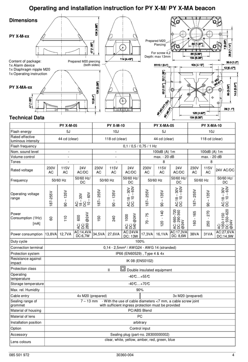
Schéma de perçage de l’intérieur du boîtier
4. Caractéristiques techniques
4.1Généralités
PY L-S
Intensité lumineuse 76 cd (clair)
Source lumineuse 1x DEL haute puissance
Couleurs DEL RGBW
bleu, rouge, vert, jaune
en plus avec une commande externe : blanc
Facteur de marche 100 %
Bornes 0,14 - 2,5 mm² à fil fin / AWG24 - AWG 14
Indice de protection IP 66 (EN 60529), type 4 & 4x
Résistance aux chocs IK08 (EN 50102)
Classe de protection II
Température de service -40 °C… +55 °C
Température de stockage -40 °C… +70 °C
Humidité relative max. 90 %
Entrée de câble 4x M20 avec empreinte préalable
Zone d’étanchéité
du passe-fil
7 – 13 mm En cas d’utilisation de câbles de diamètre < 7 mm, prévoir un
presse-étoupe d’un indice de protection suffisant
Matériau du boîtier PC/ ABS Blend
Matériau du capot PC
Position de montage au choix
Couleurs du capot
transparent, blanc, jaune, orange, rouge, vert, bleu
Version RGBW : blanc
Encoche préparée pour le M20

Instructions de service PY L-S
03/2021 Page 3 / 8 086200015b
fr
4.2 Caractéristiques électriques
Plage de tensions
assignées
12 – 48 V CC 24 V CA
50/60 Hz
115 - 230 V CA
50/ 60 Hz
120 V CC
Plage de tensions de
service 10 – 60 V CC 21,6 –
26,4 V CA
90 – 265 V CA
108 -132 V CC
Consommation de
courant assignée
(max.)
12 V CC
24 V CC
48 V CC
167 mA
120 V CC
115 V CA
230 V CA
275 mA 120 mA 65 mA 74,4 mA 51 mA 36 mA
Puissance absorbée
(max.) 3,3 W 2,9 W 3,1 W 4 VA 2,93 W 5,9 VA 8,3 VA
5. Admissions
(Les homologations sont valables pour les appareils marqués)
UL, cUL E189090
UEES, UEES7 (pour plus d’informations, voir la page 3 de la partie en langue anglaise)
6. Mise en service
6.1 Consignes de sécurité
DANGER- Danger de mort par décharge électrique
Les appareils sous tension et les câbles de raccordement dénudés peuvent provoquer des dé-
charges électriques et des accidents graves.
Les travaux sur les branchements électriques ne peuvent être effectués que par des profes-
sionnels agréés, formés en électrotechnique.
Avant le montage, débrancher tous les câbles d’alimentation électrique et veiller à ce que le
courant ne soit pas rétabli. S’assurer toujours de l’absence de tension.
Attendre la fin de la phase de décharge de 5 minutes pour les composants électriques.
L’appareil peut ensuite être ouvert.
La tension de service ne doit être appliquée que lorsque le boîtier est solidement fermé.
AVERTISSEMENT - Risque lié à une utilisation non conforme des appareils
Une utilisation non conforme peut entraîner des accidents graves.
Lors de l’installation, s’assurer que le câble de raccordement est protégé contre la traction et
la torsion.
Les appareils sont uniquement destinés à une installation stationnaire.
DANGER - Risque lié à la détérioration des appareils
Le non-respect des indications de la plaque signalétique peut entraîner des accidents
graves.
Lors de l’installation et de la maintenance des appareils, toujours tenir compte des indications
figurant sur la plaque signalétique.
ATTENTION - Risque de blessures par des arêtes vives ou des composants chauds
Porter des gants lors des travaux d’installation, de montage ou d’entretien / de maintenance.
Réaliser le câblage à l’écart des arêtes vives, des coins pointus et des composants internes.
ATTENTION – Risques d’altération de la vision
Pour prévenir toute altération de la vision, éviter de regarder en permanence et directement le
feu activé.

Instructions de service PY L-S
03/2021 Page 4 / 8 086200015b
fr
Ouverture du boîtier
Fermeture du boîtier
La partie supérieure
peut être retirée en
desserrant les quatre
vis du couvercle.
Pour refermer le
boîtier, tourner les vis
du couvercle jusqu’à
la position finale de
verrouillage.
À la livraison, l’appareil n’est pas verrouillé.
Des bouchons de plombage sont disponibles dans les accessoires pour les vis du boîtier.
Passage des câbles
Le raccord fileté à membrane fourni peut être remplacé par un presse-étoupe ou par un connecteur M12 avec
une bride de dimension M20.
Monter uniquement des presse-étoupes présentant un indice de protection supérieur ou égal à IP66 au
niveau des perçages prévus à cet effet.
En cas d’utilisation de câbles de diamètre < 7 mm, prévoir un presse-étoupe d’un indice de protection suffisant.
Protection IP 66 seulement lors-
que le pavillon de la membrane
est orienté vers l’extérieur.
Après le montage du câble,
enlever le reste de la mem-
brane.
Raccord fileté à mem-
brane IP 66
(fourni)
Presse-étoupe
IP 66
(option)
Connecteur M12 IP 66,
pour appareils à très basse
tension
(option)
6.2 Branchement électrique
Tenir compte des Consignes de sécurité !
Platine de raccordement dans la partie inférieure :
PY L-S avec DEL monochrome
PY L-S avec DEL multicolore (RGBW)
3/8
1. 2.
3/8
1. 2.
Raccordement de la
tension de service
CA
:
CC
:
Raccordement de la
tension de service
CA
:
CC
:

Instructions de service PY L-S
03/2021 Page 5 / 8 086200015b
fr
Remarque : les appareils à tension continue (CC) sont dotés d’une protection contre l’inversion de polarité. Le
fonctionnement n’est pas garanti en cas d’inversion de la polarité des raccordements.
7.1 Réglage des modes opératoires - Versions avec DEL monochrome (sans commande externe)
Platine dans le capot :
S1
Choix du mode
opératoire
Commande de l’intensité lumineuse
Flash : 10 – 100 %
Clignotant / Fixe : 45 – 100 %
S1
Mode opératoire
*Réglage d’usine
1
2
3
OFF
OFF
OFF
Flash 1 Hz *
OFF
OFF
ON
Flash 0,75 Hz
OFF
ON OFF
Fixe
OFF
ON ON
Clignotant 1 Hz
ON OFF
OFF
Flash 2 Hz
ON OFF
ON
Clignotant 2 Hz
ON ON OFF
Flash 0,1 Hz
ON
ON
ON
Flash 0,5 Hz
OFF
OFF
ON Mode double flash (DFM3), voir Option
7.2 Réglage des modes opératoires - Versions avec DEL multicolore (RGBW)
Platine dans le capot :
S1
Choix du mode
opératoire
Commande de
l’intensité lumineuse
Flash
: 10 – 100 %
Clignotant
/ Fixe : 45 – 100 %
7.2.1 Sans commande externe
S1
Mode opératoire
1
2
3
OFF
OFF
OFF
Flash 1 Hz *
OFF
OFF
ON
Flash 0,75 Hz
OFF
ON OFF
Fixe
OFF
ON ON
Clignotant 1 Hz
ON OFF
OFF
Flash 2 Hz
ON
OFF
ON
Clignotant 2 Hz
ON ON OFF
Flash 0,1 Hz
ON ON ON
Flash 0,5 Hz
OFF
OFF
ON
Mode double flash (DFM3), voir Option
S1
Affectation des
couleurs
4
5
6
OFF
OFF
OFF
Rouge *
OFF
ON
Bleu
ON
OFF
Vert
ON ON Jaune
*Réglage d’usine

Instructions de service PY L-S
03/2021 Page 6 / 8 086200015b
fr
7.2.2 Avec commande externe
Réglage sur la platine dans la partie inférieure :
S1 Mode opératoire
1 2 3 4 C1 / C2
non
commandé
OFF
OFF
OFF
ON
Veille
Clignotant 1 Hz
Fixe
Fixe
OFF
OFF
ON Veille Fixe Fixe Fixe
OFF
ON OFF
Veille Clignotant 1 Hz Fixe Clignotant 1 Hz
OFF
ON
ON
Veille
Flash 1 Hz
Fixe
Fixe
ON OFF
OFF
Veille
Flash 1 Hz
Fixe
Clignotant 1 Hz
ON OFF
ON
Veille
Flash 1 Hz
Fixe
Flash 1 Hz
ON ON OFF
Veille
Clignotant 1 Hz
Clignotant 1 Hz
Clignotant 1 Hz
ON ON ON
Veille
Fixe
Fixe
Clignotant 1 Hz
Option DFM
Veille DFM1 DFM2 DFM3
OFF
OFF
ON
S1
Affectation des couleurs :
C1 / C2
non
commandé
456
ON
OFF OFF
Veille
Rouge
Vert
Bleu
OFF ON
Veille
Rouge
Vert
Jaune
ON OFF
Veille
Rouge
Vert
Blanc
ON ON
Veille
Jaune
Vert
Rouge
8. Option
Mode double flash
DFM1 DFM2 DFM3
PY L-Savec DEL monochrome :
Le mode double flash DFM3 est disponible en lieu et place du mode « Flash 1 Hz ».
PY L-S avec DEL multicolore (RGBW) :
Grâce à la commande externe (voir 7.2.2 Avec commande externe), il est possible de choisir entre DFM1,
DFM2 et DFM3.
Other manuals for PY L-S
1
Table of contents
Languages:
Other Pfannenberg Lighting Equipment manuals

Pfannenberg
Pfannenberg AB Assembly instructions

Pfannenberg
Pfannenberg Quadro LED-TL User manual

Pfannenberg
Pfannenberg Quadro LED-RGB-3G/3D User manual

Pfannenberg
Pfannenberg BR 50 Manual

Pfannenberg
Pfannenberg PMF 2015-M Product guide

Pfannenberg
Pfannenberg Quadro-LED HI User manual

Pfannenberg
Pfannenberg Quadro-LED Flex-3G/3D User manual

Pfannenberg
Pfannenberg ABL User manual

Pfannenberg
Pfannenberg PY L-S-TL User manual

Pfannenberg
Pfannenberg PY L-S-TL User manual