Tynetec Reach IP User manual

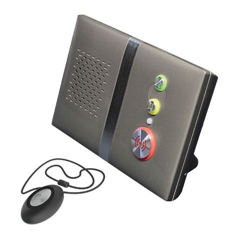
Fig1:Partsinthebox
Fig2:Buttons,StatusLED&Connections
Fig3:TouchPendantWearingOptions
1.0Partsinthebox(seeFig1)
#Item
1ReachIPAt‐HomeAlarmunit
2ACAdapterincluding UK&EUmainsplugoptions
3Connector CoverformountingtheReachIPflat
4StandformountingtheReachIPvertically
5ScrewforfixingtheStand orConnectorCover
6TouchPendant&WearingOptions(neckcord/wriststrap/beltclip)
2.0Buttons,StatusLED&Connections(seeFig2)
#Function
RedAlarmButton:make anemergencycall
GreenCancelButton:cancelanemergencycallmadeinerror
YellowFunctionButton: toggleHome/Awaymode(ifenabled)
BlackPowerButton: on/offandenterControl Mode/ServiceMenu
StatusLED: off isnormal (Green nosignal,Red alarm,Amber fault)
SUPPLY5VDCinputfromACAdapter
USBProgrammingPort (factoryuseonly)
ETHERNETConnectiontotheInternetviaaRouter (future upgrade)
3.0TouchPendantWearingOptions(seeFig3)
TheTouchPendantisaportablealarmtriggerthatcanbewornaroundtheneck,on
thewristorclippedtoabelt.ThePendantisalreadyregisteredtotheReachIPunit
andreadytouse,justfitthedesiredwearingoptionasdescribedbelow;
NeckCord:liethecordthroughoneofthegroovesontherearonthePendantthen
slidetheneckcordattachmentintoplace.Note:smallercordendmarkedinFig3.
WristStrap:feedthewriststrap(patternsideup)throughthe2slotsinthewrist
strapattachment.Note:locatethepipmarkedinthecentreholeinFig3.
Pushthealuminiumfixingstudthroughtheholemarkedattheendofthestrap.
BeltClip:simplyclipintoplaceontherearofthePendant.Note:thesuctioncupcan
befittedtothebeltcliptostickthePendanttoahardsurface,e.g.atiledwall.
3.1Setting‐uptheReachIPunit
1.PlugtheACAdapterintothemainssupply.
2.PlugtheACAdapterLeadintotheReachIPunitSUPPLYport.
3.Switchthemainssupplyonatthewall,pressandholdthePowerbuttonfora
coupleofsecondsuntilthe3frontbuttonsilluminatebrieflythenrelease.TheRed
Alarmbuttonwillremainlitifilluminationisenabled(default)andtheStatusLEDwill
belitgreenuntilaGSMsignalisestablishedthenitwillgoout.
4.IMPORTANT:rangetestthePendantfromallextremesofthehome‐seesection4.4
5.MakeanalarmcalltotheAlarmReceivingCentre(ARC)tocheckoperation.
3.2MakinganAlarmCall
PresstheAlarmbuttonandtheunitwillannounce“callingforhelp‐pleasewait”
whenanalarmcallisbeingmade.TheAlarmbuttonwillflashred.Itispossibleto
cancelthealarmwithinthefirst5secondsbypressingtheCancelbutton.
4.0ControlMode&ServiceMenu
TheReachIPisnormallyinidlemode;ControlModeandServiceMenuarewaysof
easilyreconfiguringtheunit.Theunitwillreturntoidlemodeafterachangeismade
orafter5secondsofinactivity.
ControlModeFunctions
EnterControlModebypressingthePowerbuttononce,theunitwillbeepandthe
andbuttonswillilluminate.TheControlModefunctionsarelistedbelow;
#ControlModeFunctions
RedAlarmButton:toggleRedAlarmButtonillumination on/off
GreenCancelButton:changespeechandsounds volume
YellowFunctionButton:enterServiceMenu (seebelow)
ServiceMenuFunctions
OnceinControlMode,pressandholduntiltheunitannouncesthefirstService
Menufunction“addradiodevice”thenrelease,thebuttonwillbeflashing.Press
thebuttontosequentiallystepthroughthefunctions,pressthebuttontoselect
therequiredfunction.TheServiceMenufunctionsarelistedbelow;
#ServiceMenuFunctions
1AddRadioDevice
2RangeTestMode(alsoincludesGSMSignalStrengthMode)
3DeleteRadioDevices
4Home/AwayActivityFunction
4.1ToggleRedAlarmButtonIllumination
PressthePowerbuttontoenterControlModethenpressandholduntiltheunit
announcesthenewRedButtonstatee.g.iftheilluminationwasONthenitwill
announce“functionisdisabled”andilluminationwillnowbeoff,ifitwasOFFthenit
willannounce“functionisenabled”andilluminationwillnowbeon.
4.2ChangeSpeechandSoundsVolume
PressthePowerbuttontoenterControlModethenthenpressandholduntilthe
unitsoundsanumberofbeepstoindicateitsSPEECHvolumesetting‐continue
holdingtocyclethroughthe3settingsandreleaseontherequiredsetting.Press
andholdagainwithin5secondstochangetheSOUNDlevelsetting.
4.3AddRadioDevice
PressthePowerbuttontoenterControlModethenpressandholduntiltheunit
announces“addradiodevice”thenrelease.Pressthebuttontoconfirmthen
activatetheradiodevice.Theunitwillsoundahighbeepifit’sanewdeviceand
announce“rangetestmode”‐presstoconfirm,orpresstosteptothenext
function,orpresstoexitthemodeandtheunitwillannouncethenextfunction.
Note:ifthedevicealreadyexistsalowbeepwillsound.
4.4RangeTestMode
PressthePowerbuttontoenterControlModethenpressandholduntiltheunit
announces“addradiodevice”thenrelease.Pressagainandtheunitwillannounce
“rangetestmode”thenpresstoconfirm.Theandbuttonswillbeflashing.
GotoallextremesofthehomeandpressthePendant,theReachIPwillrespondwith
abeepandthePendantbuttonwillflashgreenifthesignalisreceived.Presstoexit
themodeandtheunitwillannouncethenextfunction.
ReachIP
At‐HomeAlarm
Screwfor
Stand/Cover
ACAdapterwith
UK&EUPlugs
TouchPendant&
WearingOptions
Connector
Cover
Stand
ReachIPunit
Red
AlarmButton
Green
CancelButton
Yellow
Function
Button
Status
LED
Touch
PendantNeckCord
Attachment
WristStrap
Attachment
BeltClip
Attachment
Black
PowerButton
Ethernet
Port
USB
Port
Supply
Port
UserGuide
WristStrap
NeckCordwith
SafetyBreak
Aluminium
FixingStud
Suction
Cup
RearConnectorArea
TrustedTechnology
CaringforPeople

4.4.1GSMSignalStrengthIndication
DuringRangeTestModetheStatusLEDwillindicatetheGSMsignalstrength,seetable
below;
GSMSignalStrengthRSSIStatusLED
High21‐31SolidGreen
Good 11‐200.1SecFlashingGreen
Low1‐100.5SecFlashingGreen
NoSignal0NotLit
4.5DeleteRadioDevices
PressthePowerbuttontoenterControlModethenpressandholduntiltheunit
announces“addradiodevice”thenrelease.Repeatedlypressuntiltheunit
announces“deleteradiodevices”thenpresstoconfirm.Activatetheradiodeviceto
beremovedandabeepwillbeheard.Pressandholduntilabeepisheard,andthe
unitwillannouncethenextfunction.
4.5.1DeletingALLRadioDevices
PressthePowerbuttontoenterControlModethenpressandholduntiltheunit
announces“addradiodevice”thenrelease.Repeatedlypressuntiltheunit
announces“deleteradiodevices”thenpresstoconfirm.Pressandholduntila
beepisheardthenrelease.Pressandholdagainuntilabeepisheard,andtheunit
willannouncethenextfunction.
4.6Home/AwayActivityFunction
PressthePowerbuttontoenterControlModethenpressandholduntiltheunit
announces“addradiodevice”thenrelease.Repeatedlypressuntiltheunit
announces“homeawayactivityfunction”thenpresstoconfirm.Theunitwill
announceitscurrentstate;“functionisdisabled”or“functionisenabled”.Tochange
thesettingpressandholduntiltheunitannouncesthenewstate,theunitwillthen
announcethenextfunction.Note:ifenabledtheFunctionButtonisusedinidle
modetotoggleHome/Awaymode.
5.0ErrorIndications
Anerrorisindicatedbya“blurp”oravoicemessage;e.g.“powerdisconnected”or
“GSMnetworkfailure”.Thiswillrepeatevery2minutesuntiltheproblemisresolved
orthebuttonispressedtosilencethewarning.Errorsarealsoindicatedonthe
StatusLED,seethetablebelow;
StatusLED PossibleReasonSuggestedAction
SolidGreen NoGSM
networksignalCheckGSMnetworksignalstrength
FlashingRedMainsfailureCheckmainssupplyand/orACadapter
connection
SolidAmberBatteryfailure
ornotchargingCheck/replacebattery
Flashing
Green/Red/Amber
Radio
Interference
Checkinterferingradiosources.Move
DECTphones,WiFiRoutersetc.at
least1metreawayfromtheReachIP
6.0SwitchingtheReachIPOff
TheReachIPusesverylittlepowerandshouldalwaysbeleftswitchedon.Iftheunitis
beingremovedandstoredforaprolongedperiod,thenitshouldbeswitchedoff.
PressandholdthePowerbuttonuntilall3frontbuttonsandtheStatusLEDflash
oncethenrelease;theunitisnowswitchedoff.
7.0ImportantInformation
Itisveryimportanttoreadandunderstandthissectionbeforeuse.
Keeptheseinstructionsinasafeplaceforfuturereference.
7.1Use&Maintenance
•OperatingTemperatureRange:+5to+45°C
•Donotdamagetheunitoritsparts,ifdamagedcontactyoursupplierimmediately
•Donotexposetodirectsunlight
•Keepawayfromdust,moistureanddirt
•Donotdrop,knock,twistorshakethedevice
•Donotwarmupthedeviceoruseitnearafire
7.2Cleaning
•AllpartsintheReachIPkitcanbecleanedwithamildsoapsolutionandadamp
cloth.Drywithasoftdrycloth.
•Strongchemicalsandotherharshsubstancesmustnotbeusedwhencleaningor
handlingthepartsintheReachIPkit.
•TheReachIPmustbedisconnectedfromthemainssupplybeforecleaning.
•Aftercleaning,confirmthattheunitworksproperlybymakingatestalarmcalltothe
AlarmReceivingCentre.
7.3SafetyNotes
•Readinstructionsbeforeuse
•Alwaystesttheproductaspertheinstructionsbeforeuse
•Alwayscheckthefunctionoftheproductaftermakingchangestosettings
•Thisproductmaynotbesuitableforallpersonsandshouldnotbeasubstitutefor
theroutinevisualmonitoringbyaCarer.
•Thisproductmustnotbeusedinsituationswhereadelayinthearrivalof
appropriatemedicalcarecouldleadtoapotentiallylife‐threateningsituation.
•Testtheproductregularlyandreplacewhennecessary.
•Donotintegratewithothersystemsotherthanthosespecifiedbythemanufacturer.
•Alwayskeeptheproductdry,exposuretoexcessivemoisturecancausemalfunction.
•Thisproductwillnotcauseelectromagneticdisturbancesundernormalworking
conditions.
•Thisproductcanbeplacednearotherproductsordevicesaslongasmechanical
vibrationisnotpresent.
•Removethebatteryiftheunitistobeoutofuseorstoredforanextendedperiod.
7.4Disposal
Thecrossed‐outwheeliebinsymbolontheproductindicatesitisclassedas
ElectricalorElectronicEquipmentandshouldnotbedisposedofincommercial
wasteatitsendoflife.
TheWasteofElectrical&ElectronicEquipment(WEEE)Directive(2012/19/EU)has
beenputinplacetorecycleproductsusingthebestavailablerecoveryandrecycling
techniquestominimizeimpactontheenvironment,treathazardoussubstancesand
avoidincreasedlandfill.Forproductdisposalpleasecontactyoursuppliertocheckthe
termsandconditionsofthepurchasecontract.Alwaysensurethisproductisnot
mixedwithcommercialwastefordisposal.
8.0Specification
•ReachIPcomplieswiththeSocialAlarmStandard:EN50134‐3:2012
•Dimensions:120mmx187mmx38mm(HxWxD)
•Weight:455grams(excPSU)
•PendantFrequency:869.2125MHz
•Maxtransmissionpower:50.000μV/m
•Protocols:TS50134‐9(SCAIP),BS8521&TT92
•PowerSupply:100‐240VAC50/60Hz<5Watts
•ACAdapterType:KSAS0050500100D5D(5VDC1.0ARated)
•BatteryType:3.6VNiMH1000mAh
9.0EUDeclarationofConformity
Changesormodificationsnotexpresslyapprovedbythepartyresponsiblefor
compliancecouldvoidtheuser’sauthoritytooperatetheequipment.
ThisdevicecomplieswithEMCEmissions&ImmunityStandards;
EN61000‐6‐3:2007+A1:2011
EN50130‐4:2011+A11:2014
Operationissubjecttothefollowingtwoconditions:(1)Thisdevicemaynotcause
harmfulinterference,and(2)thisdevicemustacceptanyinterferencereceived,
includinginterferencethatmaycauseundesiredoperation.
ThisdevicecomplieswiththeRadioEquipmentDirective;
ETSIEN300220‐3‐1V2.1.1(2016‐12)
Theselimitsaredesignedtoprovidereasonableprotectionagainstharmful
interferenceinaresidentialinstallation.Thisequipmentcangenerate,useandradiate
radiofrequencyenergyand,ifnotinstalledandusedinaccordancewiththe
instructions,maycauseharmfulinterferencetoradiocommunications.However,
thereisnoguaranteethatinterferencewillnotoccurinaparticularinstallation.Ifthis
equipmentdoescauseharmfulinterferencetoradioortelevisionreception,whichcan
bedeterminedbyturningtheequipmentoffandon,theuserisencouragedtotryto
correcttheinterferencebyoneormoreofthefollowingmeasures;
•Re‐orientateorrelocatethedevice
•Increasetheseparationbetweentheequipmentandreceiver
•ConnecttheequipmentintoaMainsoutletonacircuitdifferentfromthattowhich
thereceiverisconnected
•Consultthesupplieroranexperiencedradio/TVtechnicianforhelp
ChrisDodd
ManagingDirector,LegrandAssistedLiving&HealthcareUK.
TynetecisabusinessunitofLegrandElectricLtd,
Unit10CowleyRoad,BlythRiversideBusinessPark,
Blyth,Northumberland,NE245TF,UK.
Tel:+44(0)1670352371Web:www.tynetec.co.uk DocNo.FM0802V1.04
Other manuals for Reach IP
1
Table of contents
Other Tynetec Security System manuals

Tynetec
Tynetec Reach Plus Troubleshooting guide

Tynetec
Tynetec Aidcall FM0743 User manual

Tynetec
Tynetec reach ultra Manual

Tynetec
Tynetec ZXT830 User manual

Tynetec
Tynetec Aidcall User manual

Tynetec
Tynetec SayPhone V2 User manual

Tynetec
Tynetec Advent xt Operating instructions

Tynetec
Tynetec Aidcall ZXT434 User manual

Tynetec
Tynetec Altec Response User manual

Tynetec
Tynetec ZXT812 User manual