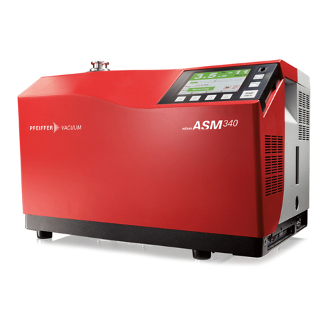
Pfeiffer Vacuum ASM 306S User manual
Other Pfeiffer Vacuum Security Sensor manuals

Pfeiffer Vacuum
Pfeiffer Vacuum MiniTest 300 User manual
Pfeiffer Vacuum
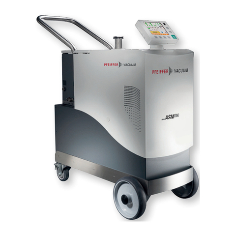
Pfeiffer Vacuum ASM 380 User manual

Pfeiffer Vacuum
Pfeiffer Vacuum ASI 35 Operating and maintenance instructions
Pfeiffer Vacuum
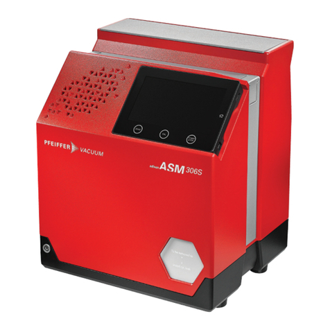
Pfeiffer Vacuum ASM 306S Manual
Pfeiffer Vacuum
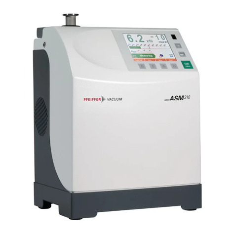
Pfeiffer Vacuum ASM 310 User manual
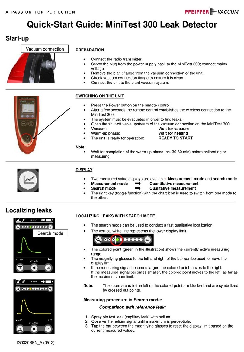
Pfeiffer Vacuum
Pfeiffer Vacuum MiniTest 300 User manual

Pfeiffer Vacuum
Pfeiffer Vacuum ASM 390 Manual
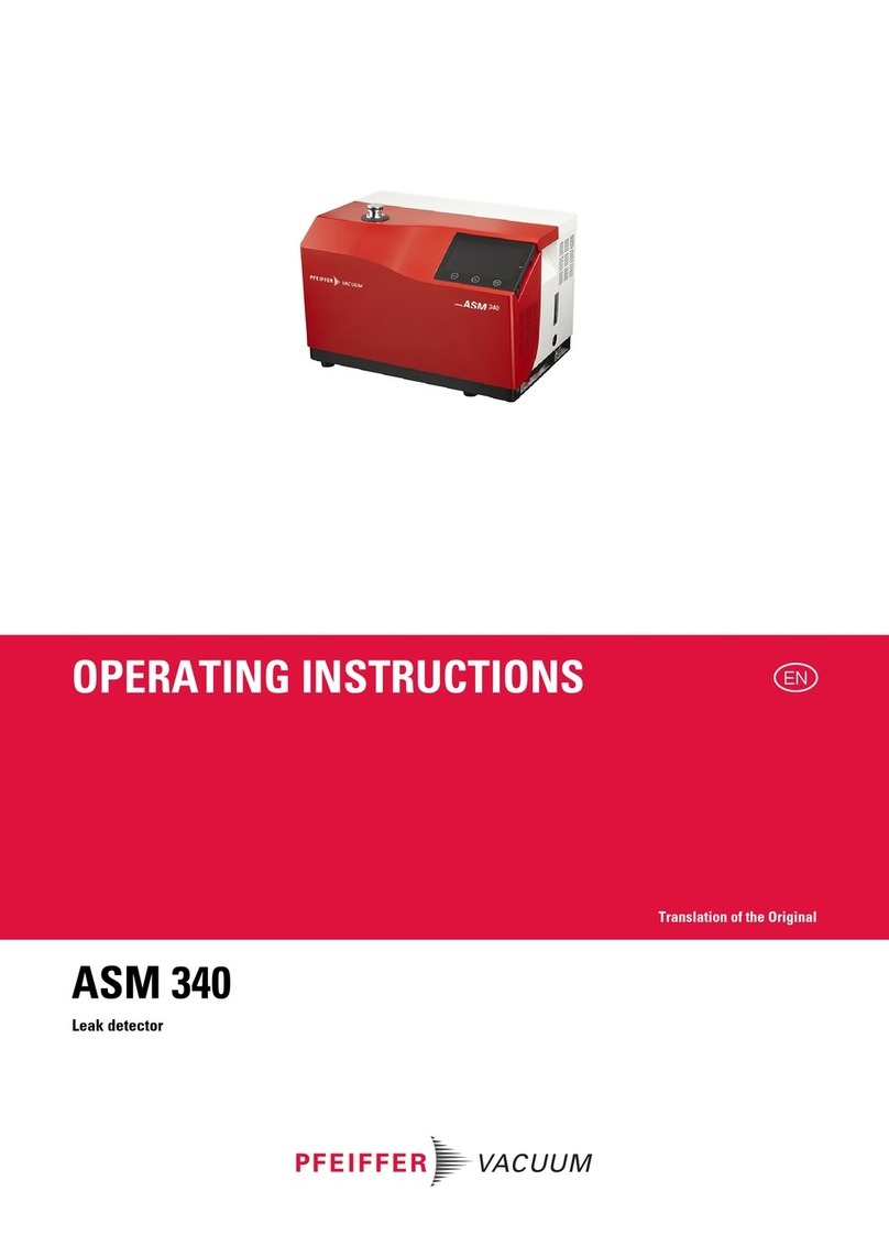
Pfeiffer Vacuum
Pfeiffer Vacuum ASM 340 User manual
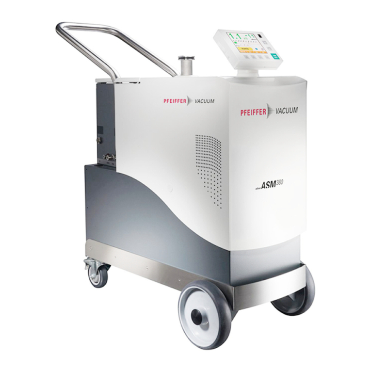
Pfeiffer Vacuum
Pfeiffer Vacuum ASM 380 MEMO User manual
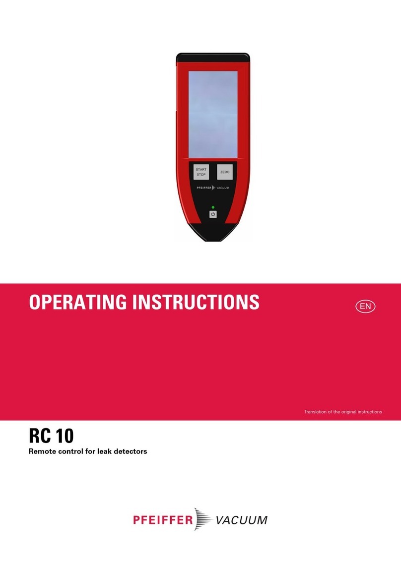
Pfeiffer Vacuum
Pfeiffer Vacuum RC 10 User manual
Pfeiffer Vacuum
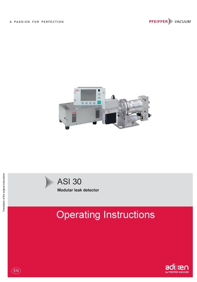
Pfeiffer Vacuum adixen ASI 30 User manual
Pfeiffer Vacuum
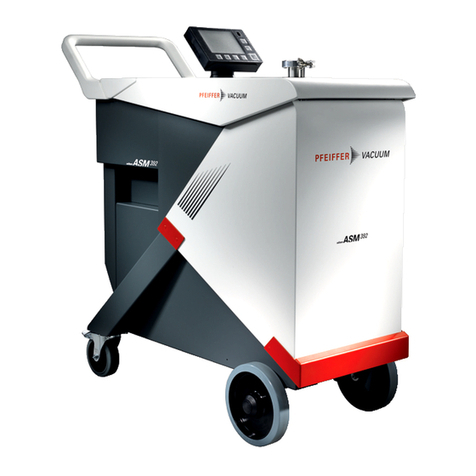
Pfeiffer Vacuum ASM 390 User manual
Pfeiffer Vacuum
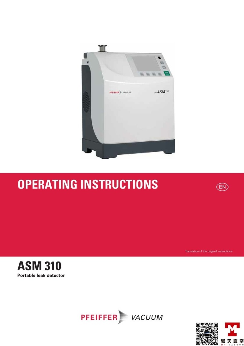
Pfeiffer Vacuum ASM 310 User manual

Pfeiffer Vacuum
Pfeiffer Vacuum ASM 390 Technical specifications
Pfeiffer Vacuum
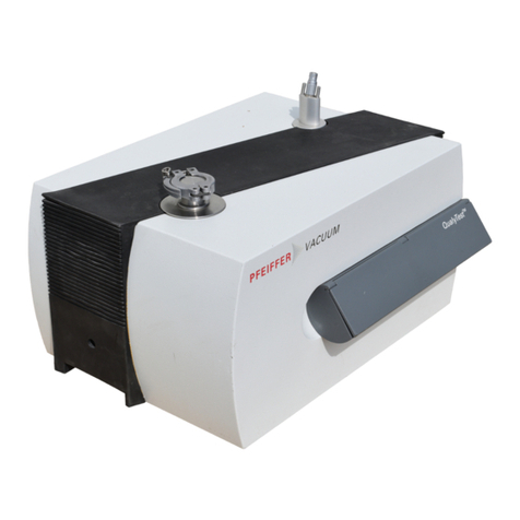
Pfeiffer Vacuum QualyTest HLT 260 Technical specifications

Pfeiffer Vacuum
Pfeiffer Vacuum ASI 35 User manual

Pfeiffer Vacuum
Pfeiffer Vacuum ASI 35 Technical specifications

Pfeiffer Vacuum
Pfeiffer Vacuum ASM 310 Operating and maintenance instructions
Pfeiffer Vacuum
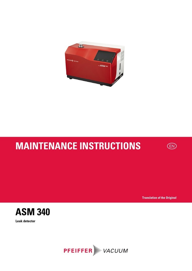
Pfeiffer Vacuum ASM 340 D Operating and maintenance instructions
Pfeiffer Vacuum
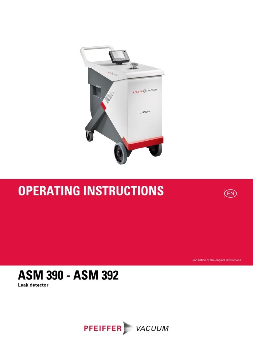
Pfeiffer Vacuum ASM 390 User manual
Popular Security Sensor manuals by other brands

Shinko
Shinko SE2EA-1-0-0 instruction manual

Det-Tronics
Det-Tronics X Series instructions

ACR Electronics
ACR Electronics COBHAM RCL-300A Product support manual

TOOLCRAFT
TOOLCRAFT 1712612 operating instructions

Elkron
Elkron IM600 Installation, programming and functions manual

Bosch
Bosch WEU PDO 6 Original instructions

