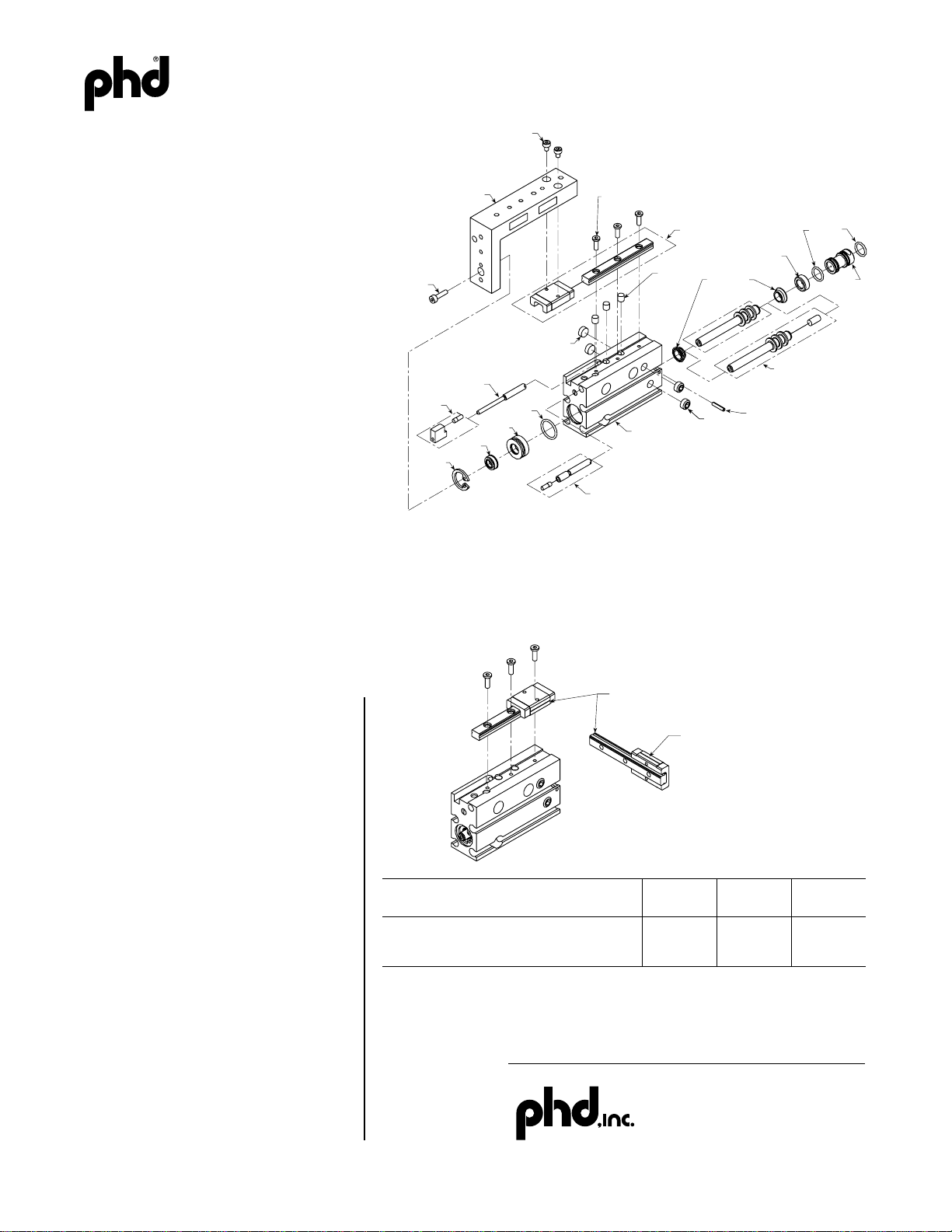
PISTON SEALS
WEAR RING
PISTON SEALS
(OPTIONAL MAGNET -M)
SIZE 08 UNITS SIZE 12 & 16 UNITS
SIZE 08 UNITS SIZE 12 UNITS
.144 [3.6]
.154 [3.9]
FIGURE 3: PIN INSERTION, in [mm]
RAIL MOUNTING SCREW
(QTY VARIES WITH TRAVEL)
RAIL & CARRIAGE
ASSEMBLY PLUG SEAL
BORE
PLUG
PISTON SEAL
PISTON & ROD
ASSEMBLY
SPRING PIN
(08 & 12 SIZES ONLY)
PORT
PLUG
BODY ASSEMBLY
PORT PLUG
EXTEND TRAVEL
ADJUSTMENT SCREW
STOP
ASSEMBLY
CARTRIDGE
CARTRIDGE
SEAL
ROD SEAL
CARTRIDGE
RETAINER
RETRACT TRAVEL
ADJUSTMENT ASSEMBLY
TOOL PLATE TO
CARRIAGE SCREW
(2 OR 4)
TOOL PLATE
TOOL PLATE TO
ROD SCREW
PORT
PLUG
WEAR RING
TRAVEL
ADJUST
PLUG
6441-417C
SERIES SHP SEAL REPLACEMENT PROCEDURES
DISASSEMBLY
1) Remove the tool plate to carriage and the tool plate to rod
screws. Lift the tool plate from the rail and carriage assembly.
2) Remove the top two side fittings or port plugs on the 12 mm
and 16 mm bore units, or the bottom two side fittings or port
plugs on the 08 mm bore unit.
3) Remove the cartridge retainer, using the appropriate tool.
4a) On the 8 and 12 mm bore units, press out the spring pin. Pull
the piston and rod assembly, as well as the cartridge assembly,
out of the front of the unit. From the rear of the body,
apply pressure to the bore plug until the rear
plug seal just becomes visible in the top-most
side ports. To prevent seal damage, insert a
5/32" [4 mm] diameter dowel into each of these
ports, and apply inward pressure to the dowels with your
fingers as you apply pressure to the rear of the bore
plug. The plug should easily press past the side
ports. Remove the dowel pins, and using a suitable
tool (a wooden dowel works well), press the bore
plug out of the front of the unit.
4b) On the 16 mm units, remove the bore plug and
cartridge retainers using the appropriate tool. Pull
the piston and rod assembly (along with the
cartridge) out of the front of the unit. Push the bore
plug out of the rear of the unit using a wooden or
plastic rod. Exercise caution not to scratch the sealing
surfaces inside the bore of the unit.
5) Discard old bore plug seals, cartridge seals, piston
seals, and rod seal. On 8 mm units, remove the wear
ring (see FIGURE 2). A pocketknife or small flat blade
screwdriver may be used to slowly force the wear ring
off of the piston and rod assembly. The wear ring may also be pressed or cut
off. Regardless of removal technique, be very careful not to damage the piston
and rod assembly.
6) Clean and inspect all components. Worn or damaged bearing components
should be replaced.
REASSEMBLY
1) In general, use a petroleum-based lubricant (grease) for the
lubrication of the slide during assembly.
2) Re-lubricate and assemble the rod seal into the cartridge, with
the shaft wiper side of the seal facing towards the tool plate end of
the cartridge. Install the cartridge seal onto the cartridge and lightly
lubricate. Install bore plug seals and lightly lube.
3a) On 8 and 12 mm units, insert the bore plug into the front of the
unit, and gently push in using a suitable rod. Push the plug into the body until the
rear plug seal just becomes visible in the top-most side ports. To prevent seal
damage, insert a 5/32" [4 mm] diameter dowel into each of the top side ports, and
apply constant inward pressure to the pins with your fingers. Holding the pressure
on the pins, push the bore plug into position. Align the spring pin groove with the
holes in the body. A fitting or suitable screw may be installed in the bore plug port
and used to rotate the plug to align the spring pin groove with the spring pin hole in
the body. Install the spring pin to the proper depth per FIGURE 3.
3b) On 16 mm units, insert the plug from the rear of body, making sure the side
communication hole is lined up with a side port. Install the plug retainer using the
proper tool.
4) Lightly lubricate and install the piston seals. See FIGURE 2 for the proper seal
orientation. On 8 mm units, install the wear ring (see FIGURE 2). The wear ring is
pressed onto the end of the piston and rod assembly. The chamfered side of the
wear ring is installed toward the piston seals. When pressing on the wear ring, support the piston and rod assembly so that the installation force does not bend the
piston rod. Also be careful not to scratch or damage the piston and rod assembly.
5) Install the rod seal cartridge onto the rod, making sure the end of the rod passes
through the rod seal before applying force. NOTE: There are two versions of rod
seal cartridges. To identify which end of the cartridge to insert into the body,
look inside the cartridge. The end with the smaller diameter opening should
be inserted into the body.
(continued on reverse side)
For additional technical assistance, call:
P.O. Box 9070, Fort Wayne, IN 46899
1-800-624-8511
FIGURE 2
FIGURE 1