PHD GRR DESIGN 2 Series User manual

6441-525D
1
SERIES GRR DESIGN 2 [6] GRIPPER
REPAIR PROCEDURES
PHD, Inc. makes no warranty as to the fitness of its products or as to the length of service life after being repaired of parts replaced by anyone
other than authorized employees of PHD, Inc. In no event shall PHD, Inc. be liable for loss of profits, indirect, consequential, or incidental
damages arising out of the use of PHD products.
Warning: All air pressure in the unit must be relieved prior to disassembly of gripper.
Caution: Care should be taken to avoid impacting piston rod during disassembly and reassembly.
Do not scratch bearing or sealing surfaces. Care should be taken to note location and
orientation of seals during disassembly.
OPTIONS -SPP99, -STT99 AND -Axxxx
DISASSEMBLY PROCEDURES
If these options are included in your gripper, these instructions
must be performed before general disassembly is begun.
Option -SPP99 & -STT99 Disassembly Procedure
Remove fasteners (8) retaining Jaw Position Sensor (30).
Remove sensor from unit, if applicable. Remove seal or spring (6).
See figure 1.
Travel Adjustment Collars Kit Disassembly Procedure
Remove fasteners (62) and travel adjustment collars (60, 61) on
open, if applicable.
TIP: Measure and record location of adjustment collars.
Collars may be removed on close if desired. See figure 2.
Option -Axxxx Disassembly Procedure
Loosen set screws (46) in travel limiting tubes (47) on open, if
applicable. Set screws may be loosened on close if desired. Note
location of each tube for reassembly. See figure 3.
figure 1
JAW POSITION SENSOR
(-SPP99 & STT99 OPTION)
JAWS IN OPEN
POSITION
6
8
8
30
60
62
61
figure 3
-Axxxx OPTION
46
47
46
47
46
47
46
47
figure 2
TRAVEL ADJUSTMENT
COLLARS KIT

6441-525D
2
D3
GENERAL DISASSEMBLY (figure 4)
1) Remove fasteners (20, 21 & 22) in end plates (15 & 16). See D1
2) (Models GRR12) Extend end plates and move jaw assemblies (17)
to full open position.
Tip: Rotate end plates 90 degrees.
3) Remove rack fastener (19) from jaw assembly. See D2
Note: Units with Rodlok (H47) will require Rodlok device (25E)
to be pressurized to allow movement of jaws. See figure 5.
4) Remove jaw assembly (17) and end plates (15 & 16) from jaw
guides (11 & 12).
(Models GRR22) Note orientation of communication plugs (14)
and o-ring seals (13) when removing jaw assemblies. This will be
important for reassembly.
Note: Units with Rodlok (H47) will require Rodlok device (25E)
to be pressurized to allow removal of jaws. See figure 5.
6) Jaw guides (11 & 12) may be removed from centerplate
assembly (4).
7) (Models GRR12) Loosen fasteners (5) retaining centerplate
assembly (4) to base plate. Press or use a soft mallet on loosened
fasteners to separate centerplate assembly from base plate (1).
See D3
Remove fasteners (5) and seals (3 & 32). See figures 4 & 6.
8) (Models GRR12) If racks and pinion are to be re-lubricated, pull
racks (9) from centerplate assembly (4). Bearings (4E & 4C) and
pinion (4D) in centerplate assembly may be removed.
Note orientation. See figures 4 and 6.
D1
figure 6
(GRR12)
CENTER PLATE
DISASSEMBLY
WARNING!
DO NOT LUBRICATE
COUPLING O-RING
OR COUNTERBORE
32
4E
4D
4C
4B
4
4B
13
14
22
21
20
15
19
18
17
9
10
4
2
3
9
18
19
17
16
20
21
22
13 14
1
6
7
5
8
11
12
10
figure 4
GENERAL DISASSEMBLY
figure 5
RODLOK
25E
PRESSURIZE TO
DISASSEMBLE
AND REASSEMBLE
D2

6441-525D
3
NOT INCLUDED
IN JAW ASSEMBLY
17L
15
17K 17G
16
17H
17J
17P
17R
17N
17T
17U 17E
17W
17V
17W 17A
17F
17F
17C 17D
17M
17Y 17L
JAW DISASSEMBLY (figure 7)
9) With piston rod (17N) retracted into jaw (17A), remove fasteners
(17L) retaining jaw center cover (17Y) and seal (17M). See D4
10) Remove shaft wipers (17D & 17F). See D5 and D6
Remove wear ring (17C). See D7
11)To allow removal of piston rod seal (17H) a spanner tool
is required. See figure 8 for dimensions. See D8
While retaining end plates (15 & 16) to prevent rotation, use
spanner tool to rotate piston (17U) counterclockwise until loose.
See D9
Piston rod may stay attached to either piston or end plate.
12) Pull end plates (15 & 16) away from jaw (17A). See D10
Note: Piston rod may stay in end plate or may be retained in jaw
assembly.
Remove remaining fasteners (17L) and remove jaw end cover
(17K). See D11
13) Remove shaft wipers (17E & 17F) and rod seal retainer (17G).
See D12
Remove piston (17U) from jaw assembly. See D13
14) Remove seals (17H & 17J) from rod seal retainer, noting
orientation. See D14
Remove seals (17W) and wear ring (17V) from piston. Note
orientation of seals for reassembly.
Caution: Care should be taken to not scratch or damage sealing
surfaces.
15) Clean and inspect all components. Worn or damaged components
should be replaced. Contact PHD for any components not included
in seal kit.
figure 7
JAW DISASSEMBLY (17)
figure 8
SPANNER
DIMENSIONS
1.182
[30 mm]
2X .256
[6.5 mm]
D4 D5 D6
D8 D9
D10
D13
D11 D12
D7
D14

6441-525D
4
13
14
22
21
20
15
19
18
17
9
10
4
2
3
9
18
19
17
16
20
21
22
13 14
1
6
7
5
8
11
12
10
= REMOVABLE THREAD LOCKER
= PETROLEUM BASED LUBRICANT/GREASE
= PETROLEUM BASED HIGH PRESSURE GREASE
NOTES:
1) Be careful to avoid damaging seals during reassembly.
2) Lubrication guidelines (only use lubricants compatible with
pneumatic devices):
•Piston,pistonrod,pistonbore,allseals[except(32)on
GRR12 units]: petroleum-based lubricant/grease
•Racks,pinion,rackspacerandbearingboresinjaws:
petroleum-based high pressure grease
3) Use removable threadlocker on all threaded fasteners.
CENTERPLATE AND BASE REASSEMBLY
1) (GRR12) Heavily lubricate rack tubes (10) and pinion cavity in
centerplate assembly (4) See A1, pinion (4D) and racks (9).
See A2
Warning: Do not allow any lubricant to enter counterbore at end
of pinion.
See figure 10 Insert bearings (4C & 4E) and pinion (4D) into
centerplate assembly. Inspect counterbore in end of pinion (4D)
for presence of grease, oil, or other foreign material.
See A3 and A4
2) If necessary, clean counterbore with cotton-tipped swab dipped in
alcohol. Install o-ring (32) into counterbore at end of pinion.
See A5 Use an Allen wrench or flat-bottomed round tool pressed
against face of o-ring to push o-ring down into counterbore.
With tool held against face of o-ring, rotate tool several turns to
properly seat o-ring in pinion.
Warning: Do not lubricate o-ring (32).
3) (GRR12) Insert racks (9) simultaneously through rack tube (4B)
and centerplate assembly. See A6 Verify that both racks protrude
equal distances from centerplate, otherwise unit will not function
properly. See A7
4) (GRR12) Lightly lubricate and install seal (3) in counterbore in base
plate (1). See A8 Using dowel pins (2) to align, place center plate
assembly on base plate. Install fasteners (5) through base plate
and torque into centerplate per TABLE 1 on next page. See A9
Centerplate and base reassembly continued on next page.
figure 9
GENERAL REASSEMBLY
WARNING!
DO NOT LUBRICATE
COUPLING O-RING
OR COUNTERBORE
32
4E
4D
4C
4B
4
4B
figure 10
CENTER PLATE
ASSEMBLY
(GRR12)
A1 A2 A3
A4 A5
A6 A7
A8 A9

6441-525D
5
5) If jaw guides were removed, lightly lubricate jaw guide holes in
center plate assembly (4) with high-pressure grease.
See figure 10. Install jaw guides (11 & 12) through centerplate
assembly. See figure 9.
Leave racks in the open position with the threaded ends about
1/4" [6 mm] from end of base plate.
6) Lubricate heavily the ID of the long rack cover (10) See A10 and
place in counterbore of center plate (4) around rack (9). See A11
7) (-Axxxx) Place closed position stroke limiting tubes (47) onto jaw
guide (11). See figure 11.
TORQUE
in-l
bN
m
300 33.9
5.
6
40 4.5
100 11.3
150 16.9
300 33.9
20 2.3
300 33.9
PART DESCRIPTION
Base plate to center plate SFHCS
Sensor cover SHCS
Center and end cover SFHCS
Piston
Rack spacer fastener LHCS
End plate assembly fasteners SHCS
Stop limiting tubes set screw
Stroke adjustment collars SHCS
TABLE 1
ASSEMBLY TORQUES
ASSEMBLY
ITEM NO.
5
8
17L
17U
19
20, 21, & 22
46
62
46
47
46
47
46
47
46
47
figure 11
-Axxxx OPTION
REASSEMBLY
A10 A11
NOT INCLUDED
IN JAW ASSEMBLY
17L
15
17K 17G
16
17H
17J
17P
17R
17N
17T
17U 17E
17W
17V
17W 17A
17F
17F
17C 17D
17M
17Y 17L
17W
17V
17U
17N
17T
17W
17G
BOSS END
17H
17P
17N
17R
17J
17A BEARING BORE
PISTON BORE
PISTON BORE
COUNTERBORE
BEARING BORE
RACK COVER BORE
BEARING BORE
figure 12
JAW REASSEMBLY (17)
figure 14
SEAL RETAINER
ASSEMBLY
figure 13
PISTON ASSEMBLY
figure 15
JAW LUBRICATION
VIEW

6441-525D
6
JAW REASSEMBLY (figure 12 on previous page)
9) Curl and insert rack wear ring (17C) into groove in jaw (17A). See
A12 Verify that ring is seated completely in groove. See A13
10) Lubricate and insert rod wipers (17E & 17F) into counterbores in
jaw. Snap rod wipers (17D) into undercut groove. See A14 and A15
Verify wipers are completely seated. See A16
11) Lubricate and install o-ring (17M) into seal groove on jaw (17A).
See A17 Note: O-ring (17M) is the larger diameter of the 2 large
o-rings in kit.
12) Lubricate grooves on piston (17U) outer diameter. See A18
Start one end of piston wear ring (17V) into center groove of
piston. Push the wear ring into the goove around the piston until
it snaps in. See A19 and A20
Install piston seals (17W) into grooves on either side of piston
wear ring. See figure 13 for orientation.
Lubricate outside diameter of piston and seals.
13) Lubricate and install seals (17P & 17R or 17T) on piston rod
(17N). See A21, A22, and A23
Lubricate OD of piston rod (17N).
Do not apply lubricant to threads.
14) Lubricate internal and external seal grooves of seal retainer (17G).
See A24 Install o-ring (17J) and rod seal (17H) into seal retainer.
See figure 14 for orientation. Lubricate ID of rod seal and OD
of o-ring. Note: O-ring (17J) is the smaller of the 2 larger o-rings
supplied in kit.
15) Seal retainer (17G) assembly over piston rod (17N):
a) If piston rod remained attached to piston (17U) during
disassembly, with a rotating motion slide seal retainer over
piston rod with boss of retainer pointed away from piston.
See A25 and A26
b) If piston rod remained attached to end plate (15 or 16), place
jaw end cover (17K), with countersinks facing end plate,
See A27 over piston rod. See A28 With a rotating motion,
slide seal retainer over piston rod with boss of retainer facing
end plate. See A29
Seal should move freely after rod and piston assembly.
16) Piston (17U), piston rod (17N), jaw end cover (17K) and end plate
(15 or 16) subassembly:
a) If piston rod remained attached to piston, place jaw end cover
over piston rod with countersinks facing away from piston.
Apply threadlocker to piston rod thread and hand-tighten into
end plate until seated. Note: Do not torque at this time.
See drawing figures 12 and 14.
b) If piston rod remained attached to end plate, apply
threadlocker to thread at end of piston rod. Thread the piston
onto the piston rod until seated. Note: Do not torque at this
time. See drawing figures 12 and 13.
17) Lubricate piston bore, counterbore in jaw (17A), piston and seals.
See A30 and A31 Insert piston (17U) into the counterbored end
of the piston bore. See A32
Slide seal retainer (17G) against piston, press on seal retainer
until piston slides into bore and seal retainer
enters into counterbore in jaw. See A33
Outer face of seal retainer should be flush with
jaw surface.
Jaw reassembly continued on next page.
A31 A32
A15 A16 A17
A18 A19 A20
A12 A13 A14
A21 A22 A23
A24 A25 A26
A27 A28 A29 A30
A33

6441-525D
7
GENERAL REASSEMBLY (figure 9)
22) Slide jaws (17) onto jaw guides (11 & 12) until jaws reach the
open position.
Note: Units with Rodlok (H47) will require Rodlok device (25E)
to be pressurized to allow reassembly of jaws. See figure 5.
23) (GRR12) Lubricate OD of rack spacer (18) and place on rack
spacer fastener (19). Apply threadlocker to fastener. Install spacer
and fastener through hole in bottom of jaw end cover (17K) and
torque fastener into rack (9) per TABLE 1. See A38
Tip: Rotate end plates 90 degrees for this step.
24) (Axxxx) Place open position stroke limiting tubes (47) onto jaw
guide (11). See figure 11.
25) Lubricate and install o-ring seals (13) into counterbores in end
plates (15 & 16). See A39
Note: GRR12 & GRR02 use a larger o-ring than GRR22.
See figure 16.
26) (GRR22) Place communication plug (14) through o-ring (13) and
into end plates. See figure 16.
27) Align and assemble end plates (15 & 16) to base plate (1).
See figure 9.
Warning: Verify that long rack cover (10) is properly seated in
counterbores of center plate and endplates. Rack cover may
require support during assembly of end plates. See A40
28) Apply threadlocker to the fasteners (20, 21 & 22) retaining
end plates to the base plate and jaw guides. Install and torque
fasteners per TABLE 1. See figure 9.
29) (-Axxxx) Stop limiting tubes (47) with set screws (46): apply
threadlocker to set screw and torque per TABLE 1. Stop limiting
tubes without screws: clean areas where tube will contact jaw
guide, end plate or center plate. Apply threadlocker to contact
surfaces. Push tube into proper position. See figure 11.
30) Install travel adjustment collars (60 & 61) on jaw guide (11) using
threadlocker on the fasteners (62) during assembly. With fasteners
loosely tightened, move collars to proper position and torque per
TABLE 1. See figure 17.
Warning: Do not allow collars to impact piston rods during
assembly.
See next page for final reassembly.
18) Extend piston rod and end plate. Holding seal retainer in place,
align jaw end cover (17K) with holes in jaw (17A). See A34
Apply threadlocker to fasteners (17L).
Install and torque fasteners per TABLE 1.
19) Retract piston rod and end plate. Using a spanner tool, see figure
8, torque piston (17U) per TABLE 1. See A35
Warning:Propertorqueonthiscomponentiscriticaltoproper
function of unit.
20) Place jaw center cover (17Y) on end of jaw. Apply threadlocker to
fasteners (17L). Install and torque fasteners per TABLE 1.
21) Heavily lubricate the 3 bearing bores in jaw (17A) with high
pressure grease. See figure 15. See A36 and 37
figure 5
RODLOK
25E
PRESSURIZE TO
DISASSEMBLE
AND REASSEMBLE
GRR22
GRR02 & GRR12
15 16
14
13
13
figure 16
END PLATE
SEALS
60
62
61
figure 17
TRAVEL ADJUSTMENT
COLLARS
A34 A35 A36
A37
A38
A39
A40

6441-525D
8
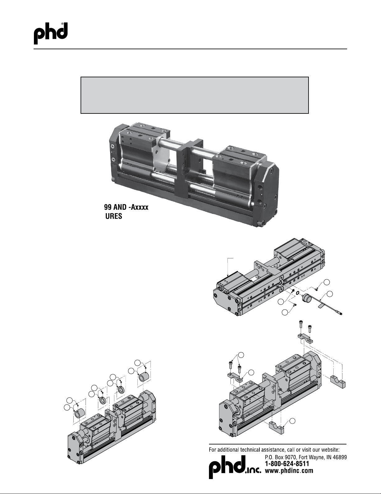
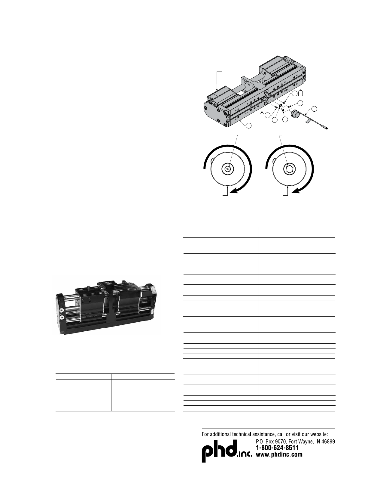
JAW POSITION SENSOR (SPP99 & STT99
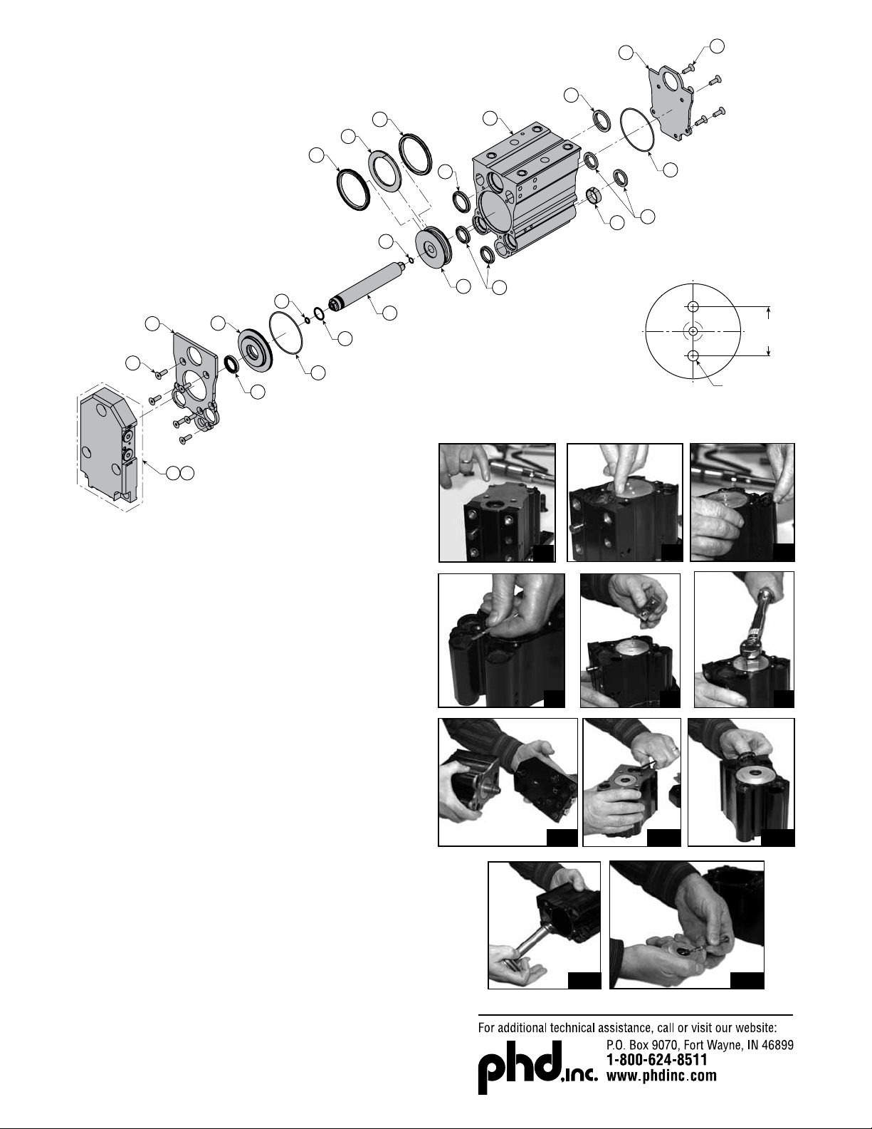
INSTALLATION (figure 18)
31) Move jaws to the full open position.
32) Insert o-ring seal (6) into shallow counterbore in base plate (1).
33) Looking at protruding shaft of sensor (30), rotate shaft clockwise
until rotation stops. See figure 18.
34) Visually align counterbores in base plate (1) and matching
notches in sensor or hexes (30).
Tip: To minimize voltage offset of sensor, position notches
in sensor slightly counter-clockwise of counterbores in base
plate. Then rotate body of the sensor clockwise to align
notches with counterbores in base plate AFTER the sensor has
been inserted into the base plate.
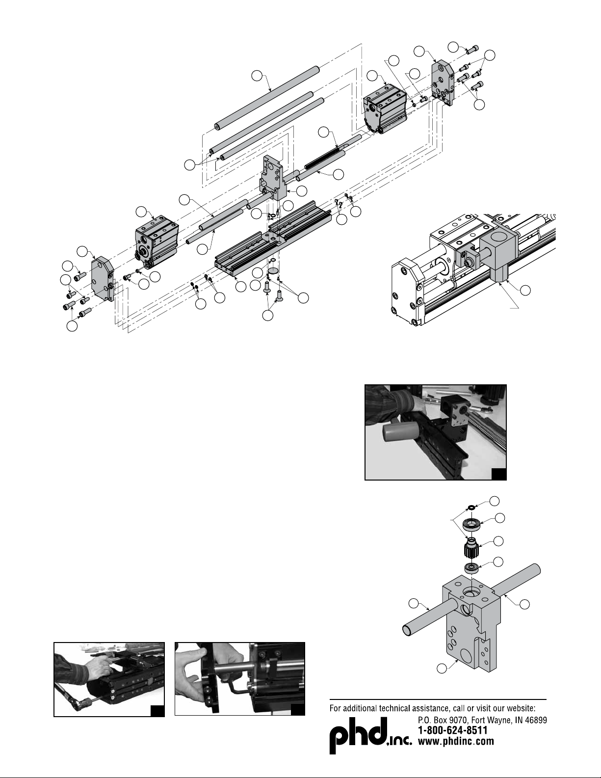
35) a. SPP99: Place end of sensor shaft against o-ring coupling (32)
in pinion and insert jaw position sensor into base plate (1).
Note: Initial resistance will be felt until sensor shaft completely
penetrates coupling o-ring allowing sensor to easily slide into
large counterbore in base plate.
b. STT99: Insert the spring (34) into the hex cutout in pinion,
then insert the jaw position sensor hex sleeve into hex cutout.
May need to rotate shaft to fit into hole hex. Only rotate as
much as needed to fit into hole.
36) Apply threadlocker to sensor cover fasteners, (8) install and
torque per TABLE 1.
Handcycletoverifyjawpositionsensorrotatesthroughthe
entirejawstroke.Ifsensorisnotinsertedcorrectly,sensor
could be damaged on STT99 sensor.
Cycle gripper a minimum of 10 times to ensure the offset voltage
output.
Note: Output voltage offset of sensor may have changed with
replacement of sensor. Check output with jaws in full open
position and adjust controller or setpoint module accordingly.
figure 18
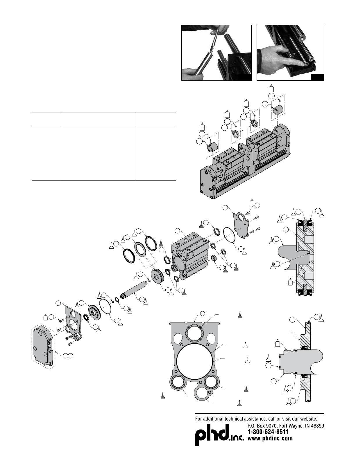
JAW POSITION SENSOR REASSEMBLY
(-SPP99 & -STT99)
PART NUMBER CALLOUT FIGURE 4 AND 9
13
14
22
21
20
15
19
18
17
9
10
4
2
2
3
9
18
19
17
16
20
21
22
13 14
1
6
7
5
8
32
11
12
10
40
42
44
41 45
43
COMPLETE
RODLOK KIT
RODLOK ADAPTOR KIT
(MOUNTING ONLY)
RODLOK KIT
(LOCKING DEVICE ONLY)
25E
25
34
without
sensor
with
sensor
30
SPP99
STT99
KITS
Full unit description required -H6100
17831-095
Sold as part of seal kit only
Full unit description required -H4810
Full unit description required -H2000
Sold as part of seal kit only
74221
Full unit description required -H2040
Full unit description required -H3310
Full unit description required -H1300
Full unit description required -H4720
Full unit description required -H4710
Sold as part of seal kit only
74213
Full unit description required -H6210
Full unit description required -H6220
Full unit description required -H2605
75038
Full unit description required -H2020
Full unit description required -H4740
Full unit description required -H2030
Full unit description required -H9110
Full unit description required -H9100
Sold as part of jaw position sensor kit
Sold as part
of sensor kit
Sold as part of sensor kit
Full unit description required -H1705
Full unit description required -H1715
Full unit description required -H1725
Full unit description required -H1735
Full unit description required -H1745
Full unit description required -H1755
PART DESCRIPTION
Base Plate Assembly
Dowel Pin
O-ring Seal
Center Plate Assembly
FHCS
O-ring Seal
Jaw Position Sensor Cover
SHCS
Rack
Rack Cover Tube
Large Jaw Guide
Small Jaw Guide
O-ring Seal
End Plate Communication Plug
End Plate Assembly (location 48)
End Plate Assembly (location 26)
Jaw Assembly
Rack Mounting Spacer
LHCS
SHCS
SHCS
SHCS
Complete Rodlok Kit (per jaw)
Rodlok Kit (per jaw)
Jaw Position Sensor Assembly
O-ring Sensor Coupling
(-SPP99 option only)
Spring - Sensor (-STT99 option only)
-ANxxx Travel Limiting Tube
-ATxxx Travel Limiting Tube
-APxxx Travel Limiting Tube
-AQxxx Travel Limiting Tube
-ARxxx Travel Limiting Tube
-AUxxx Travel Limiting Tube
PART NUMBER
KEY
1
2
3
4
5
6
7
8
9
10
11
12
13
14
15
16
17
18
19
20
21
22
25
25E
30
32
34
40
41
42
43
44
45
Note: All part numbers are for standard units. Options may affect part numbers.
*Seal kit does not include Rodlok seals. Rodlok seals sold in Rodlok seal kit only.
DESCRIPTION
Complete Rodlok Kit (per jaw)
Rodlok Kit (per jaw)
Rodlok Adaptor Kit (per jaw)
Rodlok Seal Kit (per jaw)
Seal Kit
Sensor Replacement Kit
PART NUMBER
Full unit description required -H9110
Full unit description required -H9100
Full unit description required -H9105
Full unit description required -H9115
Full unit description required -H9000
Full unit description required -H9305
13
14
22
21
20
15
19
18
17
9
10
4
2
2
3
9
18
19
17
16
20
21
22
13 14
1
6
7
5
8
32
11
12
10
40
42
44
41 45
43
COMPLETE
RODLOK KIT
RODLOK ADAPTOR KIT
(MOUNTING ONLY)
RODLOK KIT
(LOCKING DEVICE ONLY)
25E
25
34
without
sensor
with
sensor
30
SPP99
STT99
KITS
Full unit description required -H6100
17831-095
Sold as part of seal kit only
Full unit description required -H4810
Full unit description required -H2000
Sold as part of seal kit only
74221
Full unit description required -H2040
Full unit description required -H3310
Full unit description required -H1300
Full unit description required -H4720
Full unit description required -H4710
Sold as part of seal kit only
74213
Full unit description required -H6210
Full unit description required -H6220
Full unit description required -H2605
75038
Full unit description required -H2020
Full unit description required -H4740
Full unit description required -H2030
Full unit description required -H9110
Full unit description required -H9100
Sold as part of jaw position sensor kit
Sold as part
of sensor kit
Sold as part of sensor kit
Full unit description required -H1705
Full unit description required -H1715
Full unit description required -H1725
Full unit description required -H1735
Full unit description required -H1745
Full unit description required -H1755
PART DESCRIPTION
Base Plate Assembly
Dowel Pin
O-ring Seal
Center Plate Assembly
FHCS
O-ring Seal
Jaw Position Sensor Cover
SHCS
Rack
Rack Cover Tube
Large Jaw Guide
Small Jaw Guide
O-ring Seal
End Plate Communication Plug
End Plate Assembly (location 48)
End Plate Assembly (location 26)
Jaw Assembly
Rack Mounting Spacer
LHCS
SHCS
SHCS
SHCS
Complete Rodlok Kit (per jaw)
Rodlok Kit (per jaw)
Jaw Position Sensor Assembly
O-ring Sensor Coupling
(-SPP99 option only)
Spring - Sensor (-STT99 option only)
-ANxxx Travel Limiting Tube
-ATxxx Travel Limiting Tube
-APxxx Travel Limiting Tube
-AQxxx Travel Limiting Tube
-ARxxx Travel Limiting Tube
-AUxxx Travel Limiting Tube
PART NUMBER
KEY
1
2
3
4
5
6
7
8
9
10
11
12
13
14
15
16
17
18
19
20
21
22
25
25E
30
32
34
40
41
42
43
44
45
Note: All part numbers are for standard units. Options may affect part numbers.
*Seal kit does not include Rodlok seals. Rodlok seals sold in Rodlok seal kit only.
DESCRIPTION
Complete Rodlok Kit (per jaw)
Rodlok Kit (per jaw)
Rodlok Adaptor Kit (per jaw)
Rodlok Seal Kit (per jaw)
Seal Kit
Sensor Replacement Kit
PART NUMBER
Full unit description required -H9110
Full unit description required -H9100
Full unit description required -H9105
Full unit description required -H9115
Full unit description required -H9000
Full unit description required -H9305
JAW POSITION
SENSOR (30)
JAWS IN OPEN
POSITION
6
8
8
30
1
JAW POSITION
SENSOR (30)
OUTPUT SHAFT & HEX
SLEEVE ROTATE CLOCKWISE
UNTIL ROTATION STOPS
SPP99 STT99
OUTPUT SHAFT ROTATE
CLOCKWISE UNTIL
ROTATION STOPS
(STT99)
(SPP99)
32
34
This manual suits for next models
2
Table of contents
Other PHD Industrial Equipment manuals