manuals.online logo
Brands
  1. Home
  2. •
  3. Brands
  4. •
  5. Pilz
  6. •
  7. Relay
  8. •
  9. Pilz PSEN 1.1b-25 User manual

Pilz PSEN 1.1b-25 User manual

21 379-05
PSEN 1.1b-25
- 1 -
4D Betriebsanleitung
4GB Operating instructions
4F Manuel d'utilisation
21 379-05PSEN 1.1b-25
Sicherheitsschalter PSEN 1.1b-25
833792907
Der Sicherheitsschalter erfüllt Forderungen der
EN 60204-1 und IEC 60204-1.
Der Sicherheitsschalter ist zugelassen für den
Einsatz in explosionsgefährdeten Bereichen
nach EN 50021 Ex-Bereich Kategorie 3, Zone 2
(Gas) und 22 (Stäube), (II 3GD EEx nC IIC T6).
Der Sicherheitsschalter erfüllt EN 60947-5-3
nur zusammen mit der Schnittstelle PSEN ix1,
dem Betätiger PSEN 1.1-20 und hierfür zuge-
lassenen Auswertegeräten. Schließen Sie den
Sicherheitsschalter nur an Auswertegeräte an,
die im Abschnitt "Anschlüsse" aufgeführt sind.
Safety switch PSEN 1.1b-25
The safety switch meets the requirements of
EN 60204-1 and IEC 60204-1.
The safety switch is approved for use in poten-
tially explosive atmospheres in accordance
with EN 50021, Ex area Category 3, Zone 2
(gas) and 22 (dust), (II 3GD EEx nC IIC T6).
The safety switch only complies with
EN 60947-5-3 in conjunction with the PSEN ix1
interface, the actuator PSEN 1.1-20 and its ap-
proved evaluation devices. The safety switch
should only be connected to the evaluation de-
vices listed under "Connections".
Capteur de sécurité PSEN 1.1b-25
Le capteur de sécurité satisfait aux exigences
de l'EN 60204-1 et de la CEI 60204-1.
Le capteur de sécurité est homologué pour
l'utilisation dans les atmosphères explosibles
selon l'EN 50021 zone Ex catégorie 3, zones 2
(gaz) et 22 (poussière), (II 3GD EEx nC IIC T6).
Le capteur de sécurité est conforme à la norme
EN 60947-5-3 uniquement lorsqu'il est utilisé
avec l'interface PSEN ix1, l'organe de com-
mande PSEN 1.1-20 et les unités de contrôle
spécialement homologuées. Ne raccordez le
capteur de sécurité qu'aux unités de contrôle
indiquées dans le chapitre « Raccordements ».
Zu ihrer Sicherheit
547263243
`Installieren und nehmen Sie das Gerät nur
dann in Betrieb, wenn Sie diese Betriebsan-
leitung gelesen und verstanden haben und
Sie mit den geltenden Vorschriften über Ar-
beitssicherheit und Unfallverhütung vertraut
sind.
Beachten Sie die VDE- sowie die örtlichen
Vorschriften, insbesondere hinsichtlich
Schutzmaßnahmen
`Durch Öffnen des Gehäuses oder eigen-
mächtige Umbauten erlischt jegliche Ge-
währleistung.
777809547
`Entfernen Sie die Schutzkappe erst unmittel-
bar vor Anschluss des Geräts.
For your safety
`Only install and commission the unit if you
have read and understood these operating
instructions and are familiar with the applica-
ble regulations for health and safety at work
and accident prevention.
Ensure VDE and local regulations are met,
especially those relating to safety.
`Any guarantee is rendered invalid if the hous-
ing is opened or unauthorised modifications
are carried out.
`Do not remove the protective cap until you
are just about to connect the unit.
Pour votre sécurité
`Vous n'installerez l'appareil et ne le mettrez
en service qu'après avoir lu et compris le
présent manuel d'utilisation et vous être fa-
miliarisé avec les prescriptions en vigueur
sur la sécurité du travail et la prévention des
accidents.
Respectez les normes locales ou VDE, parti-
culièrement en ce qui concerne la sécurité.
`L'ouverture de l'appareil ou sa modification
annule automatiquement la garantie.
`Veuillez retirer le cache de protection avant
de raccorder l'appareil.
Gerätemerkmale
510482059
`Zum Sicherheitsschalter gehört der Betätiger
PSEN 1.1-20
704084107
`Sicherheitsschalter mit Kabel (10 m)
510237579
`2 Sicherheitskontakte (Schließer)
510312331
`gesicherter Schaltabstand: 8 mm
`gesicherter Ausschaltabstand: 26 mm
510316939
`eckige Bauform
510321547
`Wirkweise magnetisch
510477451
`Schaltspannung 24 V DC
Unit features
`The actuator PSEN 1.1-20 belongs to the
safety switch
`Safety switch with cable (10 m)
`2 safety contacts (N/O)
`Assured operating distance: 8 mm
`Assured release distance: 26 mm
`Square design
`Works magnetically
`Switching voltage 24 VDC
Caractéristiques de l'appareil
`Un organe de commande est associé au
capteur de sécurité PSEN 1.1-20
`Capteur de sécurité avec câble (10 m)
`2 contacts de sécurité (contacts à fermeture)
`distance de commutation de sécurité : 8 mm
`distance de coupure de sécurité : 26 mm
`architecture rectangulaire
`actionnement magnétique
`tension commutée 24 V DC
Schaltabstände Operating distances Distances de commutation
Seitenversatz/Lateral offset/
Décalage latéral Höhenversatz/Height offset/
Décalage en hauteur
aktive Fläche
active area
surface active
Schaltabstand/O erating distance/
Portee de travail
sao = 8
sar = 26
Ein/On/Marche
Aus/Off/Arrêt
somin = 0,5
- 2 -
Seiten- und Höhenversatz
880601995
`Gesicherter Schaltabstand Sao in mm
`Gesicherter Ausschaltabstand Sar:
Max. 26 mm bei allen Höhen- und Seitenver-
sätzen
Die angegebenen Werte sind gültig bei einer
Temperatur von 20 °C.
Lateral and vertical offset
`Assured operating distance Sao in mm
`Assured release distance Sar:
Max. 26 mm with all vertical and lateral off-
sets
The stated values are valid at a temperature of
20 °C.
Décalage latéral et en hauteur
`Distance de commutation de sécurité Sao en
mm
`Distance de coupure de sécurité Sar :
26 mm maximum pour tous les décalages
latéraux et en hauteur
Les valeurs indiquées sont valables pour une
température de 20 °C.
Verdrahtung
492354955
Beachten Sie:
`Angaben im Abschnitt „Technische Daten“
unbedingt einhalten.
`Berechnung der max. Leitungslänge Imax im
Eingangskreis:
Rlmax = max. Gesamtleitungswiderstand
(s. techn. Daten)
Rl/ km = Leitungswiderstand/km
`Beachten Sie bei Einsatz von Auswertegerä-
ten mit rückfallverzögerten Kontakten:
– Verzögerungszeit ≤30 s: die rückfallverzö-
gerten Kontakte genügen den Anforderun-
gen der Kategorie 3 gemäß EN 954-1 bzw.
den Anforderungen an PDF mit Einfehlersi-
cherheit (PDF-S).
– Verzögerungszeit ≥30 s: die rückfallverzö-
gerten Kontakte genügen den Anforderun-
gen der Kategorie 1 gemäß EN 954-1 bzw.
den Anforderungen an PDF mit Zuverläs-
sigkeit durch besonderes Design (PDF-D).
`Überprüfen Sie in folgenden Fällen von Inbe-
triebnahme die Funktion Querschlusserken-
nung:
– Bei Auswertegeräten mit Versorgungs-
spannung DC: Gesamtleitungswiderstand
≥15 Ohm pro Kanal
– Bei Auswertegeräten mit Versorgungs-
spannung AC: Gesamtleitungswiderstand
≥25 Ohm pro Kanal
– Wie Sie die Querschlussprüfung durchfüh-
ren müssen, entnehmen Sie der entspre-
chenden Bedienungsanleitung des
Auswertegeräts.
Wiring
Please note:
`Information given in the “Technical details”
must be followed.
`Calculation of the max. cable runs lmax in the
input circuit:
Rlmax = max. overall cable resistance (see
Technical details)
Rl/ km = cable resistance/km
`When using evaluation devices with delay-on
de-energisation contacts, please note:
– Delay time ≤30 s: Delay-on de-energisation
contacts satisfy the requirements of cate-
gory 3 in accordance with EN 954-1 and
the requirements of a PDF with single-fault
tolerance (PDF-S).
– Delay time ≥30 s: Delay-on de-energisa-
tion contacts satisfy the requirements of
Category 1 in accordance with EN 954-1
and the requirements of a PDF with de-
signed reliability (PDF-D).
`In the following commissioning cases, check
the function that detects shorts across con-
tacts:
– On evaluation devices with DC supply
voltage: Overall cable resistance ≥15
Ohms per channel
– On evaluation devices with AC supply volt-
age: Overall cable resistance ≥25 Ohms
per channel
– For details of how to perform the test for
shorts across the contacts, please refer to
the operating manual for the relevant eval-
uation device.
Câblage
Important :
`Tenez compte impérativement des données
indiquées au chapitre "Caractéristiques
techniques".
`Calcul de la longueur de câble max. Imax sur
le circuit d'entrée :
Rlmax = résistance max. de l'ensemble du
câblage (voir les caractéristiques techni-
ques)
Rl/km = résistance du câblage/km
`En cas de mise en œuvre d'appareils de con-
trôle avec contacts temporisés à la retom-
bée, il faut tenir compte des indications
suivantes :
–Temporisation≤30 s : les contacts tempo-
risés à la retombée satisfont aux prescrip-
tions de la catégorie 3 selon l'EN 954-1, et/
ou aux prescriptions des PDF avec sécuri-
té de défaut unique (PDF-S).
–Temporisation≥30 s : les contacts tempo-
risés à la retombée satisfont aux prescrip-
tions de la catégorie 1 selon l'EN 954-1, et/
ou aux prescriptions des PDF avec une
fiabilité obtenue grâce à un design particu-
lier (PDF-D).
`Vérifiez dans les cas suivants de mise en ser-
vice la fonction de détection des courts-
circuits :
– pour les appareils de contrôle avec ali-
mentation DC : Résistance de l'ensemble
du câblage ≥15 ohms par canal
– pour les appareils de contrôle avec ali-
mentation AC : Résistance de l'ensemble
du câblage ≥25 ohms par canal
–voustrouverezdanslanotice d'utilisation
de l'appareil de contrôle comment exécu-
ter le contrôle des courts-circuits.
Anschlüsse Connections Raccordements
Anschlussbelegung Terminal assignment Repérage des broches
807841803
Der Sicherheitsschalter ist in unbetätigtem Zu-
stand dargestellt.
The safety switch is shown in an unoperated
condition.
Le capteur de sécurité est représenté en posi-
tion de repos.
Belegung des 4-adrigen Kabels/Layout of the 4-core
cable/Repérage du câble à 4 conducteurs
5,0
3,0
1,5
1,0
2,0
2,5
3,02,01,0 4,0
6,07,07,57,5 6,5
6,07,07,57,5 6,5
6,07,07,07,5 6,5
6,5
7,07,0
7,07,0
Höhenversatz/Height offset/
Décalage en hauteur
Seitenversatz/Lateral
offset/Décalage latéral
6,5
6,5
6,5
5,5
5,5
5,0
3,0
1,5
1,0
2,0
2,5
3,02,01,0 4,0
6,07,07,57,5 6,5
6,07,07,57,5 6,5
6,07,07,07,5 6,5
6,5
7,07,0
7,07,0
Höhenversatz/Height offset/
Décalage en hauteur
Seitenversatz/Lateral
offset/Décalage latéral
6,5
6,5
6,5
5,5
5,5
5,0
3,0
1,5
1,0
2,0
2,5
3,02,01,0 4,0
6,07,07,57,5 6,5
6,07,07,57,5 6,5
6,07,07,07,5 6,5
6,5
7,07,0
7,07,0
Höhenversatz/Height offset/
Décalage en hauteur
Seitenversatz/Lateral
offset/Décalage latéral
6,5
6,5
6,5
5,5
5,5
5,0
3,0
1,5
1,0
2,0
2,5
3,02,01,0 4,0
6,07,07,57,5 6,5
6,07,07,57,5 6,5
6,07,07,07,5 6,5
6,5
7,07,0
7,07,0
Höhenversatz/Height offset/
Décalage en hauteur
Seitenversatz/Lateral
offset/Décalage latéral
6,5
6,5
6,5
5,5
5,5
5,0
3,0
1,5
1,0
2,0
2,5
3,02,01,0 4,0
6,07,07,57,5 6,5
6,07,07,57,5 6,5
6,07,07,07,5 6,5
6,5
7,07,0
7,07,0
Höhenversatz/Height offset/
Décalage en hauteur
Seitenversatz/Lateral
offset/Décalage latéral
6,5
6,5
6,5
5,5
5,5
5,0
3,0
1,5
1,0
2,0
2,5
3,02,01,0 4,0
6,07,07,57,5 6,5
6,07,07,57,5 6,5
6,07,07,07,5 6,5
6,5
7,07,0
7,07,0
Höhenversatz/Height offset/
Décalage en hauteur
Seitenversatz/Lateral
offset/Décalage latéral
6,5
6,5
6,5
5,5
5,5
Rlmax
Rl / km
Imax = Rlmax
Rl / km
Imax = Rlmax
Rl / km
Imax =
blau/blue/bleu
weiß/white/blanc
braun/brown/marron
schwarz/black/noir
- 3 -
Anschluss an Auswertegeräte Connection to evaluation devices Raccordement aux unités de contrôle
`Anschluss an PNOZ X, PNOZpower, PNOZ-
sigma, PNOZelog
`Connection to PNOZ X, PNOZpower,
PNOZsigma, PNOZelog
`Raccordement au PNOZ X, PNOZpower,
PNOZsigma, PNOZelog
PNOZ p1p
PNOZ p1vp
PNOZ X2/X2P
PNOZ X2.1
(nur 24 V DC/
24 V DC only/
24 V DC seule ent)
PNOZ X2.3P
PNOZ X2.7P
PNOZ X2.8P
PNOZ X2C
PNOZ X2.1C
(nur 24 V DC/
24 V DC only/
24 V DC seule ent)
PNOZ X4/X8P
PNOZ X9
PNOZ X10/X10.1
PNOZ X10.11
PNOZ Ex
PNOZ e1p
PNOZ e1.1p
PNOZ e1vp
PNOZ e6.1p
PNOZ e6vp
PNOZ s3
PNOZ s4
PNOZ s5
S21
S22
S11
S12
blau/blue/bleu
weiß/white/blanc
braun/brown/marron
schwarz/black/noir
11
12
13
14
1
2
3
4
PSEN ix1 1
2
3
4
S21
S22
S11
S12
blau/blue/bleu
weiß/white/blanc
braun/brown/marron
schwarz/black/noir
11
12
13
14
1
2
3
4
PSEN ix1 1
2
3
4
Nicht-Ex-Bereich/Non-Ex
area/Zone Non Ex Ex-Bereich/Ex area/
Zone Ex
PNOZ X2.9P S11
S12
S11
S52
blau/blue/bleu
weiß/white/blanc
braun/brown/marron
schwarz/black/noir
11
12
13
14
1
2
3
4
PSEN ix1 1
2
3
4
Nicht-Ex-Bereich/Non-Ex
area/Zone Non Ex Ex-Bereich/Ex area/
Zone Ex
PNOZ X5
PNOZ X5J
S11
S22
S11
S12
blau/blue/bleu
weiß/white/blanc
braun/brown/marron
schwarz/black/noir
11
12
13
14
1
2
3
4
PSEN ix1 1
2
3
4
S11
S22
S11
S12
blau/blue/bleu
weiß/white/blanc
braun/brown/marron
schwarz/black/noir
11
12
13
14
1
2
3
4
PSEN ix1 1
2
3
4
Nicht-Ex-Bereich/Non-Ex
area/Zone Non Ex Ex-Bereich/Ex area/
Zone Ex
PNOZ 11
PNOZ 16
PNOZ X11P
PNOZ X13
PNOZ X3.1
PNOZ X3P
PNOZ X2.5P
PNOZ X3
PNOZ X3.10P
PNOZ XV2
PNOZ XV2P
PNOZ XV3
PNOZ XV3P
S31
S32
S21
S22
blau/blue/bleu
weiß/white/blanc
braun/brown/marron
schwarz/black/noir
11
12
13
14
1
2
3
4
PSEN ix1 1
2
3
4
Nicht-Ex-Bereich/Non-Ex
area/Zone Non Ex Ex-Bereich/Ex area/
Zone Ex
PNOZ X6 (mit Brücke/with li k/avec po tage Y3-Y4)PNOZ X6 (mit Brücke/with li k/avec po tage Y3-Y4) S23
S24
S11
S12
blau/blue/bleu
weiß/white/blanc
braun/brown/marron
schwarz/black/noir
11
12
13
14
1
2
3
4
PSEN ix1 1
2
3
4
S23
S24
S11
S12
blau/blue/bleu
weiß/white/blanc
braun/brown/marron
schwarz/black/noir
11
12
13
14
1
2
3
4
PSEN ix1 1
2
3
4
Nicht-Ex-Bereich/Non-Ex
area/Zone Non Ex Ex-Bereich/Ex area/
Zone Ex
PMUT X1P S51
S52
S61
S62
blau/blue/bleu
weiß/white/blanc
braun/brown/marron
schwarz/black/noir
11
12
13
14
1
2
3
4
PSEN ix1 1
2
3
4
Nicht-Ex-Bereich/Non-Ex
area/Zone Non Ex Ex-Bereich/Ex area/
Zone Ex
- 4 -
`Anschluss an PNOZmulti `Connection to PNOZmulti `Raccordement au PNOZmulti
`Anschluss an PSS mit oder ohne
SafetyBUS p
`Connection to PSS with or without
SafetyBUS p
`Raccordement au PSS avec ou sans
SafetyBUS p
PNOZ e5.11p
A1
S22
A1
S12
blau/blue/bleu
weiß/white/blanc
braun/brown/marron
schwarz/black/noir
11
12
13
14
1
2
3
4
PSEN ix1 1
2
3
4
A1
S22
A1
S12
blau/blue/bleu
weiß/white/blanc
braun/brown/marron
schwarz/black/noir
11
12
13
14
1
2
3
4
PSEN ix1 1
2
3
4
Nicht-Ex-Bereich/Non-Ex
area/Zone Non Ex Ex-Bereich/Ex area/
Zone Ex
A1
S42
A1
S32
blau/blue/bleu
weiß/white/blanc
braun/brown/marron
schwarz/black/noir
11
12
13
14
1
2
3
4
PSEN ix1 1
2
3
4
A1
S42
A1
S32
blau/blue/bleu
weiß/white/blanc
braun/brown/marron
schwarz/black/noir
11
12
13
14
1
2
3
4
PSEN ix1 1
2
3
4
Nicht-Ex-Bereich/Non-Ex
area/Zone Non Ex Ex-Bereich/Ex area/
Zone Ex
Schutztür/safety gate/protecteur mobile
Schaltertyp 3/switchtype 3/type du capteure 3
I0, I1: Ei gä ge/i puts/e trées
T0, T1: Taktausgä ge/test pulse outputs/sorties
impulsio elles
T1
I1
T0
I0 blau/blue/bleu
weiß/white/blanc
braun/brown/marron
schwarz/black/noir
11
12
13
14
1
2
3
4
PSEN ix1 1
2
3
4
Nicht-Ex-Bereich/Non-Ex
area/Zone Non Ex Ex-Bereich/Ex area/
Zone Ex
Schutztür/safety gate/protecteur mobile
Schaltertyp 3/switchtype 3/type du capteure 3
I0, I1: Ei gä ge/i puts/e trées
O16, O17: Taktausgä ge/test pulse outputs/sorties
impulsio elles
O17
I1
O16
I0 blau/blue/bleu
weiß/white/blanc
braun/brown/marron
schwarz/black/noir
11
12
13
14
1
2
3
4
PSEN ix1 1
2
3
4
Nicht-Ex-Bereich/Non-Ex
area/Zone Non Ex Ex-Bereich/Ex area/
Zone Ex
- 5 -
Montage
880896011
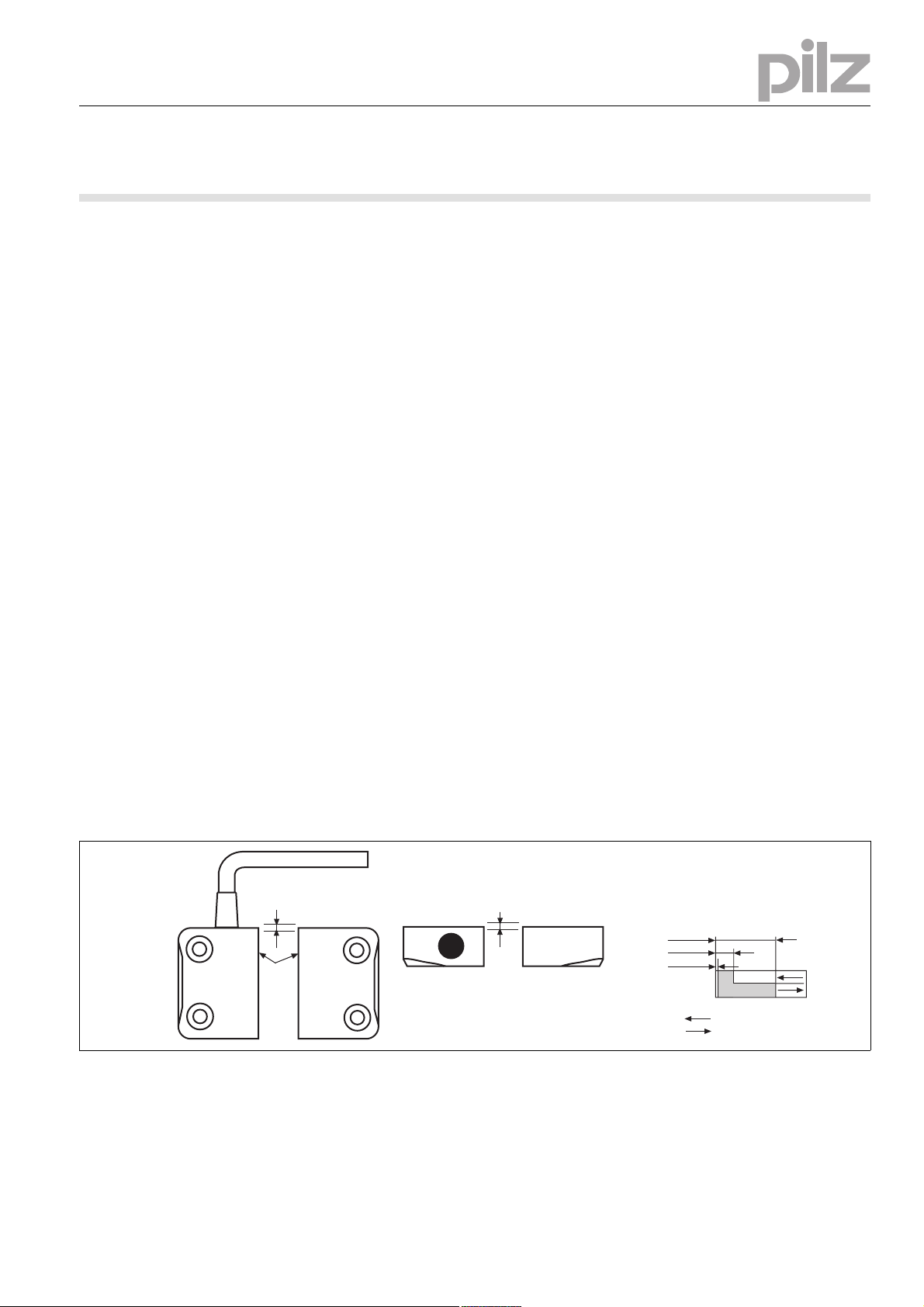
`Die Montagelage ist beliebig. Sicherheits-
schalter und Betätiger müssen jedoch paral-
lel gegenüberliegend montiert werden.
`Sicherheitsschalter und Betätiger möglichst
nicht auf ferromagnetisches Material montie-
ren. Es sind Änderungen der Schaltabstände
zu erwarten. Benutzen Sie in diesem Fall die
Distanzplatte mit der Bestell-Nr. 534 310.
`Befestigen Sie Sicherheitsschalter und Betä-
tiger ausschließlich mit Schrauben M4 mit
flacher Kopfunterseite (z.B. M4-Zylinder-
kopf- oder -Flachkopfschrauben). Anzugs-
drehmoment max. 1 Nm. Verwenden Sie
Schrauben aus nicht magnetischem Material
(z. B. Messing).
`Der Abstand zwischen zwei Systemen aus
Sicherheitschalter und Betätiger muss min-
destens 25 mm betragen.
`Sicherheitsschalter und Betätiger
– von Eisenspänen fernhalten
– keinen starken Magnetfeldern aussetzen
– keinen starken Stößen oder Schwingun-
gen aussetzen
– nicht als Anschlag benutzen
– nur für feste Verkabelung
Installation
`The unit can be installed in any position.
However, safety switches and actuators
must be positioned opposite each other in
parallel:
`If possible, do not install the safety switch
and actuator on to ferromagnetic material.
Changes to the operating distances are to be
expected. In this case, use the spacer avail-
able under order number 534 310.
`Safety switches and actuators should only
be secured using M4 screws with a flat head
(e.g. M4 cheese-head or pan head screws).
Torque setting max. 1 Nm. Use screws made
of non-magnetic material (e.g. Messing).
`The distance between two systems compris-
ing safety switch and actuator must be at
least 25 mm.
`Safety switch and actuator
– Keep away from iron swarf
– Do not expose to strong magnetic fields
– Do not expose to heavy shock or vibration
– Do not use as a limit stop
– For fixed wiring only
Installation
`Le sens de montage est indifférent. Cepen-
dant, le capteur de sécurité et l'organe de
commande doivent être montés l'un en face
de l'autre de manière parallèle.
`Evitez d'installer le capteur de sécurité et
l'organe de commande sur du matériel ferro-
magnétique. Les distances de commutation
peuvent être modifiées. Utilisez dans ce cas
le support séparateur portant la référence
534 310.
`Pour fixer le capteur de sécurité et l'organe
de commande, utilisez uniquement des vis
M4 dont la tête présente une face inférieure
plate (par ex. une vis M4 cylindrique ou à tête
plate). Couple de serrage maxi 1 Nm. Utilisez
des vis en métal non magnétique (par ex. en
laiton).
`La distance minimale entre deux systèmes
de capteur de sécurité et d'organe de com-
mande doit être d'au moins 25 mm.
`Le capteur de sécurité et l'organe de com-
mande
– doivent être éloignés des copeaux métalli-
ques
– ne doivent pas être exposés à des champs
magnétiques élevés
– ne doivent pas subir des chocs et vibra-
tions importants
– ne doivent pas être utilisés comme butée
– uniquement pour câblage fixe
Justage
1112614923
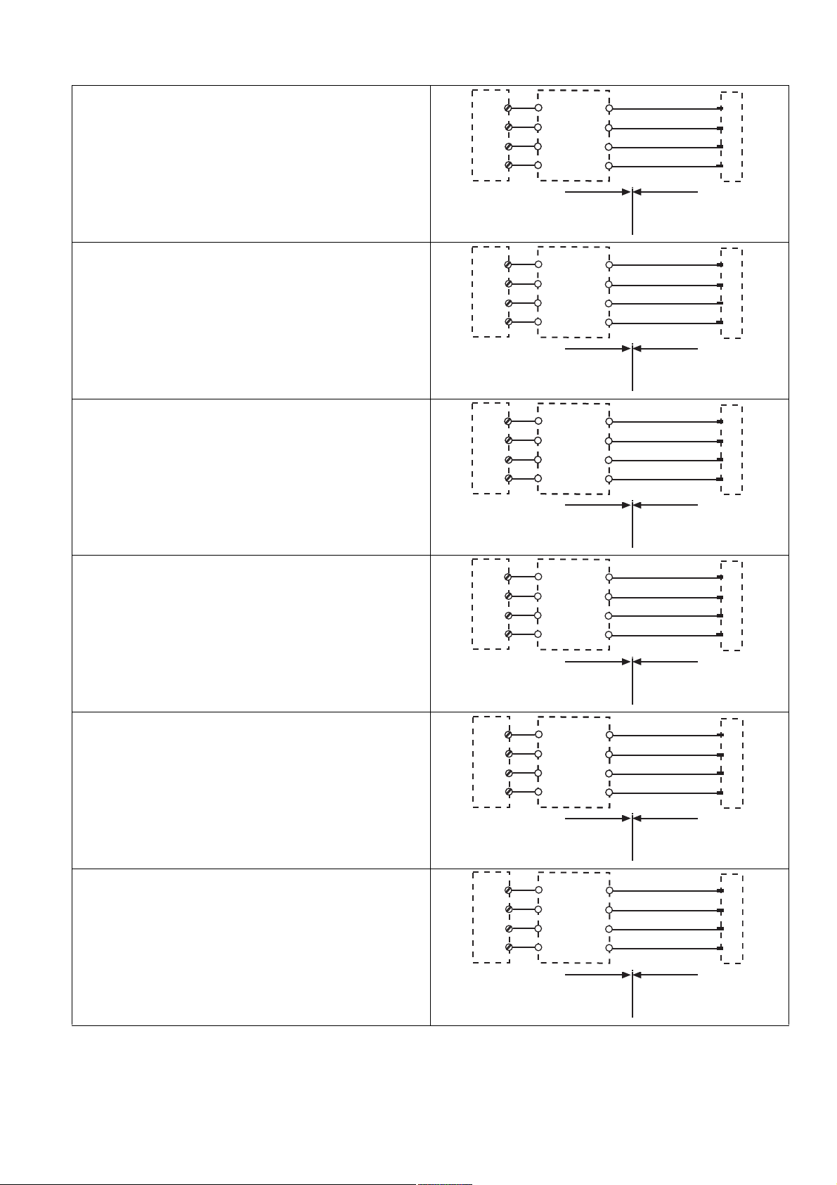
`Der Sicherheitsschalter darf nur mit dem zu-
gehörigen Betätiger PSEN 1.1-20 verwendet
werden.
`Prüfen Sie die Funktion immer mit der
Schnittstelle PSEN ix1 und einem der zuge-
lassenen Auswertegeräte.
`Die angegebenen Schaltabstände (siehe
technische Daten) gelten nur, wenn Sicher-
heitsschalter und Betätiger parallel gegen-
überliegend montiert sind. Andere
Anordnungen können zu abweichenden
Schaltabständen führen. Beachten Sie den
maximal zulässigen Seiten- und Höhenver-
satz (siehe "Schaltabstände" und "Max. Sei-
ten- und Höhenversatz").
Adjustment
`The safety switch may only be used with the
corresponding actuator PSEN 1.1-20.
`Always test the function with the PSEN ix1
interface and one of the approved evaluation
devices.
`The stated operating distances (see Techni-
cal details) only apply when the safety switch
and actuator are installed facing each other
in parallel. Switching distances may deviate
if other arrangements are used. Note the
maximum permitted lateral and vertical off-
set (see "Operating distances" and "Max. lat-
eral and vertical offset").
Ajustement
`Le capteur de sécurité ne doit être utilisé
qu'avec un organe de commande
PSEN 1.1-20 adapté.
`Vérifiez la fonction toujours avec l'interface
PSEN ix1 et l'un des appareils de contrôle
homologués.
`Les distances de commutation mentionnées
dans les caractéristiques techniques sont
valables uniquement lorsque le capteur de
sécurité et l'organe de commande sont mon-
tés l'un en face de l'autre de manière parallè-
le. D'autres montages peuvent conduire à
des distances de commutation divergentes.
Respectez le décalage latéral et vertical
maximal autorisé (voir "Distances de com-
mutation" et "Décalage latéral et vertical
maximum").
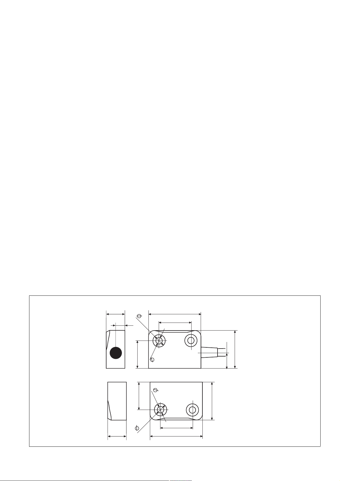
Abmessungen Dimensions Dimensions
26
19
22
36
10,6
8,5
4,5
13
6,5
26
19
22
36
8,5
4,5
13
afety switch
Actuator
Originalbetriebsanleitung/Original instructions/Notice originale
21 379-05, 2009-12 Printed in Germany Printed in Germany
21 379-052009-12Printed in Germany
Technische Daten Technical details Caractéristiques techniques
Elektrische Daten Electrical data Données électriques
Schaltspannung Switching voltage Tension de commutation 24 V
Max. Schaltstrom Sicherheitskon-
takte
Max. switching current for safety
contacts
Courant max. de commutation des
contacts de sécurité
0,50 A
Max. Schaltleistung Sicherheits-
kontakte
Max. breaking capacity for safety
contacts
Puissance max. de commutation
des contacts de sécurité
10,0 W
Max. Schaltfrequenz Max. switch frequency Fréquence de commutation max. 1 Hz
Umweltdaten Environmental data Données sur l'environnement
ATEX Kategorie ATEX category Catégorie ATEX II 3GD EEx nC IIC T6
Umgebungstemperatur Ambient temperature Température d'utilisation -10 - 70 °C
Schwingungen nach EN 60947-5-2 Vibration to EN 60947-5-2 Vibrations selon EN 60947-5-2
Frequenz Frequency Fréquence 10 - 55 Hz
Amplitude Amplitude Amplitude 1,00 mm
EMV EMC CEM EN 60947-5-3
Schockbeanspruchung Shock stress Résistance aux chocs 30g , 11 ms
Verschmutzungsgrad Pollution degree Niveau d'encrassement 3
Bemessungsisolationsspannung Rated insulation voltage Tension assignée d'isolement 250 V
Bemessungsstoßspannungsfestig-
keit
Rated impulse withstand voltage Tension assignée de tenue aux
chocs
4,00 kV
Mechanische Daten Mechanical data Données mécaniques
Betätiger Actuator Actionneur PSEN 1.1-20
Hysterese typ. Hysteresis typ. Hystérésis env.
Betätiger PSEN 1.1-20 Actuator PSEN 1.1-20 Actionneur PSEN 1.1-20 5,0 mm
Schaltabstände Switching distances Distances de commutation
Gesicherter Schaltabstand
Sao PSEN 1.1-20 Assured operating distance
Sao PSEN 1.1-20 Portée de travail assurée Sao
PSEN 1.1-20 8 mm
Min. Schaltabstand Somin
PSEN 1.1-20 Min. operating distance
Somin PSEN 1.1-20 Portée de travail min. Somin
PSEN 1.1-20 0,5 mm
Gesicherter Ausschaltabstand
Sar PSEN 1.1-20 Assured release distance Sar
PSEN 1.1-20 Portée de déclenchement assurée
Sar PSEN 1.1-20 26 mm
Anschlussart
Kabel
Connection type
Cable
Type de connection
Câble 10 m
Leitung Cable Câble LiYY 4 x 0,25 mm²
Schutzart Gehäuse Protection type, housing Indice de protection du boîtier IP69K
Gehäusematerial Housing material Matériau du boîtier PBT
Abmessungen siehe Abbildung Dimensions, see graphic Dimensions, voir l'illustration
Gewicht Weight Poids
Sicherheitsschalter Safety switch Capteur de sécurité 320 g
Betätiger PSEN 1.1-20 Actuator PSEN 1.1-20 Actionneur PSEN 1.1-20 17 g
Sicherheitstechnische Kennda-
ten Safety-related characteristic
data Caractéristiques techniques de
sécurité
B10d nach EN ISO 13849-1 und
EN IEC 62061
B10d in accordance with
EN ISO 13849-1 and EN IEC 62061
B10d selon EN ISO 13849-1 et
EN IEC 62061
500.000
Lambdad/Lambda nach EN IEC
62061
Lambdad/Lambda in accordance
with EN IEC 62061
Lambdad/Lambda selon EN IEC
62061
0,90
Es gelten die 2009-06 aktuellen Ausgaben der
Normen.
The standards current on 2009-06 apply. Les versions actuelles 2009-06 des normes
s'appliquent.
1128680331
INFO
Bestellnummern und Zubehör finden Sie im
Technischen Katalog oder auf unserer In-
ternetseite www.pilz.com.
INFORMATION
Order numbers and accessories can be
found in the Technical Catalogue or on our
Internet site www.pilz.com.
INFORMATION
Vous trouverez les références et les acces-
soires dans le catalogue technique ou sur
notre site www.pilz.com.
EG-Konformitätserklärung
1139424011
Diese(s) Produkt(e) erfüllen die Anforderungen
der Richtlinie 2006/42/EG über Maschinen des
europäischen Parlaments und des Rates. Die
vollständige EG-Konformitätserklärung finden
Sie im Internet unter www.pilz.com.
Bevollmächtigter: Norbert Fröhlich, Pilz GmbH
& Co. KG, Felix-Wankel-Str. 2, 73760 Ostfil-
dern, Deutschland
EC Declaration of Conformity
This (these) product(s) comply with the require-
ments of Directive 2006/42/EC of the European
Parliament and of the Council on machinery.
The complete EC Declaration of Conformity is
available on the Internet at www.pilz.com.
Authorised representative: Norbert Fröhlich,
Pilz GmbH & Co. KG, Felix-Wankel-Str. 2,
73760 Ostfildern, Germany
Déclaration de conformité CE
Ce(s) produit(s) satisfait (satisfont) aux exigen-
ces de la directive 2006/42/CE relative aux ma-
chines du Parlement Européen et du Conseil.
Vous trouverez la déclaration de conformité CE
complète sur notre site internet www.pilz.com.
Représentant : Norbert Fröhlich, Pilz GmbH &
Co. KG, Felix-Wankel-Str. 2, 73760 Ostfildern,
Allemagne

Other Pilz Relay manuals

Pilz P2HZ 5 User manual

Pilz

Pilz P2HZ 5 User manual

Pilz PNOZ X3 Owner's manual

Pilz

Pilz PNOZ X3 Owner's manual

Pilz PNOZsigma Instructions for use

Pilz

Pilz PNOZsigma Instructions for use

Pilz PNOZ XV2.1P User manual

Pilz

Pilz PNOZ XV2.1P User manual

Pilz PNOZSIGMA Series User manual

Pilz

Pilz PNOZSIGMA Series User manual

Pilz PNOZ s4.1 User manual

Pilz

Pilz PNOZ s4.1 User manual

Pilz PNOZ e6.1p User manual

Pilz

Pilz PNOZ e6.1p User manual

Pilz PZE X4VP4 User manual

Pilz

Pilz PZE X4VP4 User manual

Pilz PZE X5 User manual

Pilz

Pilz PZE X5 User manual

Pilz PNOZ X2.3P User manual

Pilz

Pilz PNOZ X2.3P User manual

Pilz PNOZ X5 User manual

Pilz

Pilz PNOZ X5 User manual

Pilz S3UM User manual

Pilz

Pilz S3UM User manual

Pilz P1HZ X1 User manual

Pilz

Pilz P1HZ X1 User manual

Pilz S3UM/E User manual

Pilz

Pilz S3UM/E User manual

Pilz PNOZ X2 User manual

Pilz

Pilz PNOZ X2 User manual

Pilz PNOZ 16S User manual

Pilz

Pilz PNOZ 16S User manual

Pilz PNOZ s9 User manual

Pilz

Pilz PNOZ s9 User manual

Pilz 21398-6NL-06 User manual

Pilz

Pilz 21398-6NL-06 User manual

Pilz PNOZ X11P User manual

Pilz

Pilz PNOZ X11P User manual

Pilz PNOZ s6.1 User manual

Pilz

Pilz PNOZ s6.1 User manual

Pilz PNOZ X8P User manual

Pilz

Pilz PNOZ X8P User manual

Pilz PNOZ e3.1p User manual

Pilz

Pilz PNOZ e3.1p User manual

Pilz PNOZ X3 User manual

Pilz

Pilz PNOZ X3 User manual

Pilz PNOZ e3.1p User manual

Pilz

Pilz PNOZ e3.1p User manual

Popular Relay manuals by other brands

CARLO GAVAZZI RHS00 Installation sheet

CARLO GAVAZZI

CARLO GAVAZZI RHS00 Installation sheet

Leviton GreenMAX Series Installation

Leviton

Leviton GreenMAX Series Installation

Nibe HR 10 Installer manual

Nibe

Nibe HR 10 Installer manual

Siemens SIRIUS 3RS1000 operating instructions

Siemens

Siemens SIRIUS 3RS1000 operating instructions

Zamel exta PCM-01 instruction manual

Zamel

Zamel exta PCM-01 instruction manual

Geyer ER110ZN manual

Geyer

Geyer ER110ZN manual

Xylem FLYGT MRM 01 Installation, operation and maintenance manual

Xylem

Xylem FLYGT MRM 01 Installation, operation and maintenance manual

ABB HU Instruction leaflet

ABB

ABB HU Instruction leaflet

Taco SR502 instruction sheet

Taco

Taco SR502 instruction sheet

Zamel exta PB Series instruction manual

Zamel

Zamel exta PB Series instruction manual

Siemens 7SG12 DAD-N manual

Siemens

Siemens 7SG12 DAD-N manual

GE B90 instruction manual

GE

GE B90 instruction manual

Pontec PondoSwitch operating instructions

Pontec

Pontec PondoSwitch operating instructions

Klemsan MEASTRO Quick setup manual

Klemsan

Klemsan MEASTRO Quick setup manual

Circutor RGU-10 MT instruction manual

Circutor

Circutor RGU-10 MT instruction manual

BRP EVINRUDE ICON Series instructions

BRP

BRP EVINRUDE ICON Series instructions

Ormazabal ekor.rps General instructions

Ormazabal

Ormazabal ekor.rps General instructions

Solcon TPR-6 instruction manual

Solcon

Solcon TPR-6 instruction manual

manuals.online logo
manuals.online logoBrands
  • About & Mission
  • Contact us
  • Privacy Policy
  • Terms and Conditions

Copyright 2025 Manuals.Online. All Rights Reserved.