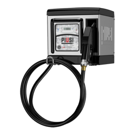
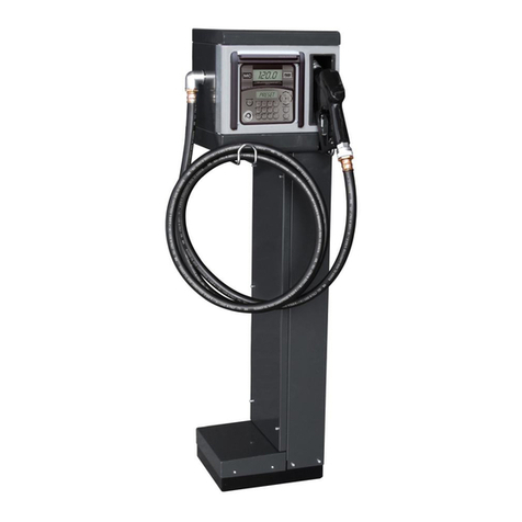
Piusi MC BOX 1.5 ETL User manual

Bulletin M0399 EN
Use and maintenance manual | EN
BOX
1.5ETL

Use and maintenance manual
2 /4 8
Bulletin Mo399 EN
ENGLISH

3
3 /4 8
EN
This manual is the property of PIUSI S.p.A. Any reproduction, even partial, is forbidden.
MCBOX1.5 ETL
Translated from Italian
TABLE Of CONTENTS
. Declaration of Conformity......................................
.. ETL Declaration of Conformity ...............................
.. EC Declaration of Conformity ................................
. General warnings.................................................
. First aid rules .....................................................
. Safety instruction ................................................
. General information .............................................
. Handling and disposal ...........................................
.. Transport, handling and unpacking............................
.. Disposal............................................................
. Use and availability of manuals ................................
.. Data plate .........................................................
. Description of main parts.......................................
.. Control system ...................................................
. Technical specifications .........................................
.. Permied uses....................................................
.. Control system performance ..................................
.. Metering precision...............................................
.. Technical data.....................................................
. Installation.........................................................
.. Hazardous areas..................................................
.. General information ............................................
.. Electrical connections...........................................

Use and maintenance manual
Bulletin M0399 EN
4 /4 8
MC BOX 1.5 ETL dispensing units described in this manual are for professional use only.
.. Electrical input/output interfaces.............................
. Commissioning ...................................................
.. Electrical power supply .........................................
.. Station configuration ............................................
.. Power-on and stand-by status .................................
.. Electronic controller configuration ...........................
.. Date and time seing............................................
. Meter calibration.................................................
. Daily use ...........................................................
. Tank level alarm states ..........................................
. Routine maintenance ............................................
. Supplementary maintenance ..................................
. MC BOX ETLexploded view..............................
. Troubleshooting ..................................................
Manifacturer’s data - Service...................................

5
5 /4 8
EN
This manual is the property of PIUSI S.p.A. Any reproduction, even partial, is forbidden.
MCBOX1.5 ETL
Translated from Italian
DECLARATION OF CONFORMITY
The undersigned:
This product is ETL listed for Canada and United States under the UL
and CSA standards.
PIUSI S.p.A.
Via Pacinoi c.m. z.i. Rangavino
Suzzara - Mantova - Italy
HEREBY STATES
under its own responsibility, that the equipment described below:
Description: DIESEL FUEL DISPENSER
Model: MC BOX 1.5 ETL
Serial number: refer to Lot Number shown on CE plate affixed to the product
Year of manufacture: refer to the year of production shown on the CE plate
affixed to the product
is in conformity with the legal provisions indicated in the directives:
¦ Low-Voltage Directive //EU
¦ Electromagnetic Compatibility Directive //EU
¦ RoHS II Directive //EU
The documentation is at the disposal of the competent authority following
motivated request at PIUSI S.p.A. or following request sent to the email address:
doc_tec@piusi.com
The person authorised to compile the technical file and draw up the declaration
is Oo Varini as legal representative.
Suzzara, // Oo Varini
the legal representative
.
. EC DECLARATION OF CONFORMITY
. ETL DECLARATION OF CONFORMITY

Use and maintenance manual
Bulletin M0399 EN
6 /4 8
.
. GENERAL WARNINGS
To ensure operator safety and to protect the dispensing system
from potential damage, workers must be fully acquainted with this
instruction manual before aempting to operate the dispensing
system.
The following symbols will be used throughout the manual to highlight
safety information and precautions of particular importance:
Warnings
Symbols used
in the manual
This symbol indicates
a hazardous situation
which, if not avoided,
could result in death
or serious injury.
This symbol
indicates that there
is risk of damage to
the equipment and/
or its components.
This symbol
indicates useful
information.
WARNING ATTENTION NOTE
This manual should be complete and legible throughout. It should
remain available to end users and specialist installation and
maintenance technicians for consultation at any time.
© PIUSI S.p.A.
THIS MANUAL IS THE PROPERTY OF PIUSI S.p.A.
ANY REPRODUCTION, EVEN PARTIAL, IS FORBIDDEN.
This manual belongs to PIUSI S.p.A., which is the sole proprietor of
all rights indicated by applicable laws, including, by way of example,
laws on copyrights. All the rights deriving from such laws are reserved
to PIUSI S.p.A. : the reproduction, including partial, of this manual,
its publication, change, transcription and notification to the public,
transmission, including using remote communication media, placing at
disposal of the public, distribution, marketing in any form, translation
and/or processing, loan and any other activity reserved by the law to
PIUSI S.p.A. All reproduction rights are reserved by PIUSI S.p.A.
The text cannot be reprinted without the wrien permission
of PIUSI S.p.A.
Manual
preservation
Reproduction
rights

7
7 /4 8
EN
This manual is the property of PIUSI S.p.A. Any reproduction, even partial, is forbidden.
MCBOX1.5 ETL
Translated from Italian
SAFETY INSTRUCTION
FIRST AID RULES
.
.
In all cases ask for a
doctor immediately.
NOTE
Disconnect the unit from the mains,
or use a dry insulator as protection
while moving the electrocuted
person far from any conductor. Do
not touch the electrocuted person
with bare hands until he/she is far
from any conductor. Ask qualified and trained people for help
immediately.
Do not operate switches with wet hands.
Electrocution
Do not operate the unit when fatigued or under the influence of drugs or alcohol.
Do not leave the work area while equipment is energized or under pressure.
Turn off all equipment when equipment is not in use.
Do not alter or modify equipment. Alterations or modifications may void agency approvals and
create safety hazards.
Route cables away from traffic areas, sharp edges, moving parts, and hot surfaces.
Keep children and animals away from work area.
Comply with all applicable safety regulations.
WARNING
All MC BOXETL models have been developed and built according to the applicable EC
rules concerning fundamental safety and health requirements.
A copy of the manufacturer’s DECLARATION OF COMPLIANCE is supplied at the beginning
of this manual.
Wear protective equipment according to the info below:
¦ suited to the operations that need to be performed;
¦ resistant to cleaning products.
Essential protective
equipment
characteristics

Use and maintenance manual
Bulletin M0399 EN
8 /4 8
Wear the following personal protective equipment during handling and
installation:
safety shoes
close-fiing clothing
protective gloves
safety goggles
Personal
protective
equipment that
must be worn
Use Instruction Manual
The device is NOT an
ANTI-EXPLOSIVE type.
The device must be installed
outside areas at risk of
explosion.
Do not install in areas where
flammable vapors may be
present.
WARNING
The device must be installed under a roof or in any environment, protected from rain.
The device must be mounted vertically with the grommets facing down.
Installation operations are carried out with the box open and accessible electrical contacts.
All these operations have to be done with the unit isolated from the power supply to prevent
electrical shock!
All work related to electrical installation must be performed by qualified installer electrical or
electronic. Wear insulated gloves for electrician.
As a general rule of electrical safety is always recommended to power the device protecting
the line with:
¦ switch/breaker with adeguate ampacity to the power line;
¦ RCD (Residual Current Device) of mA.
Devices must be professionally installed by qualified and authorized installer and it is the
professional installer’s responsibility to make sure the device is operated within local country
law and regulatory requirements.
The device is intended for use only by professional staff and authorized.
The cable must be adapted to the current capacities of the device.
Unsuitable extension cable can be dangerous.

9
9 /4 8
EN
This manual is the property of PIUSI S.p.A. Any reproduction, even partial, is forbidden.
MCBOX1.5 ETL
Translated from Italian
In accordance with current regulation only extension cable that are labelled for
outdoor use and have a sufficient ampacity should be used outdoor.
Never touch the plug and socket with wet hands. The connection between plug and
socket must stay away from water.
Before each use, check that the power cable for damage.
Replace immediately the cable connection to the network if it is damaged.
If the device is sold without cable to provide periodic verification of the circuit
grounding in accordance with current regulations.
Do not switch the dispensing system on if the network connection cable or important
parts of the apparatus are damaged, such as the inlet/outlet pipe, nozzle or safety
devices.
Replace the damaged parts immediately.
It is the installer's responsibility to provide for the accessories needed for a safe and
proper operation. The choice of accessories unfit for use, may result in damage to the
device and/or personal injury.
To maximize performance and prevent damage which may impair the functionality of
the device, require genuine accessorvies.
Stop operation immediately if static sparking occurs or if you feel a shock. Do not use
equipment until you identify and solve the problem.
PROFESSIONAL USE ONLY SYSTEM.
Do not alter or modify equipment. Alterations or modifications may void agency
approvals and create safety hazards.
MC BOXETL electronic panels are designed for the private distribution of fuel (or other
liquids). All of the models in the serie are characterised by the same form for which the MC BOX
ETL is known: a solid metal structure, high-accuracy measurements in the dispensed product
and PC soware that is designed for simplicity.
This electronic panel allows you to control and monitor private use fuel consumption via a fuel
dispenser with pump and flow meter.
The MC system consists of a multi-user panel, dedicated soware and the option accessories
for data transfer to and from the PC, using a new generation manager key.
GENERAL INFORMATION.
Use and maintenance manual
Bulletin M0399 EN
10 /4 8
Remote
PC connection
Manager
key
Pulse meter
Pump unit
Level sensor
External
nozzle switch
MC BOXETL
The MC system is composed of various devices:
◊ an electronic controller to manage fuel dispensing, equipped with:
- displays;
- keypad;
- electronic key reader;
◊ electronic user keys give access to supply and a manager key which is used for supply
configuration and discharge;
◊ a series of status sensors (e.g. dispenser nozzle positioning or tank level sensor alarm status);
◊ a flow meter - pulser that emits counter pulses to be processed by the controller;
◊ a pump that is started and stopped by the controller;
◊ client-server software for system configuration and monitoring;
◊ a key reader connected to the PC by means of a USB port.
MC BOX .ETLmust be correctly configured before dispensing any fluid. The number of type
of configuration parameters are established by the system administrator.
The basic configurations are:
◊ request of recognition of an electronic user key or a PIN CODE, or both;
◊ Creation and configuration of a tank, of a fuel dispenser;
◊ creation of a driver database
◊ configuration of the system with relevant access modes for the drivers in the relevant fuel pumps.
These configuration parameters can be modified depending on the manager needs. By means
of the software configuration page (see manual SSM) the administrator sets up the various
parameters.

11
11 /4 8
EN
This manual is the property of PIUSI S.p.A. Any reproduction, even partial, is forbidden.
MCBOX1.5 ETL
Translated from Italian
The quantity of fuel that can be dispensed is configured via software and it can be:
◊ free without PRESET;
◊ with PRESET.
Choosing preselection mode (PRESET), the operation is the following:
◊ supply of a quantity preset by the manager (PANEL PRESET), that can be changed by
the driver as well.
The bidirectional transfer of data such as seing, database and supplies can be done with a new
generation manager key only.
The panel is easy to install and adequately protected. The electrical connections are easily
accessible. The unit can be supplied complete with flow meter to be installed in line with the pump.
Construction
characteristics
Performance
Optional
¦ Panel with double display, keypad and i-buon key reader;
¦ openable metal enclosure for easy access to electrical connections;
¦ max current . Amps.
¦ Additional i-buon keys for users and manager;
¦ high precision oval gear electronic flow meter.
¦ Can manage up to / users (depending on soware version);
¦ facility to calculate consumption/period for each user;
¦ local memory up to the last fluid dispensing operations;
¦ dispensing date and time management;
¦ interfaceable with SELF SERVICE MANAGEMENT ERP soware.
Do not operate the system for any purpose other than the purpose described within this manual; all
other use is considered "IMPROPER" and will result in Piusi S.p.A. disclaiming any responsibility for
damage to property, people, animals or to the system itself.
PLANT OPERATION RESTRICTIONS:
¦ it is forbidden to use the appliance in a construction configuration other than that contemplated by
the manufacturer;
¦ it is forbidden to use the appliance with fixed guards tampered with or removed;
¦ it is forbidden to integrate other systems and/or equipment not considered by the manufacturer;
¦ it is forbidden to connect the appliance up to energy sources other than those contemplated by the
manufacturer;
¦ it is forbidden to use the commercial devices for purposes other than those indicated in this manual
¦ do not use in case of lightnings.
WARNING

Use and maintenance manual
Bulletin M0399 EN
12 /4 8
Handling and disposal.
. TRANSPORT, HANDLING AND UNPACKING
When the machine is not used, whether it is packed or unpacked, it must be stored in a place
protected from the weather (rain, damp, sun, etc.) and from dust.
To remove the cardboard packaging, use a pair of scissors or cuers, being careful not to damage
the appliance. Fully open the packaging and take out the MC BOX .ETL so that it can be taken
to the place of final installation.
Packaging parts (cardboard, wood, cellophane, etc.) must be placed in specific containers and not
le lying around or within reach of children, as these represent a potential risk hazard.
They must be disposed of according to the regulations applicable in the country of use.
Check the integrity of the machine by making sure the shipped parts are not damaged in any
way that could affect safety and operation. In case of any doubts, do not start the appliance but
contact the manufacturer's Aer-Sales Service.
MC BOX .ETL is shipped inside
stackable cardboard packaging.
Dimensions of packaging:
H = mm (")
L = mm ( ")
D = mm (")
Total weight: , kg (Lb)
Weight of packaging: kg (Lb)

13
13 /4 8
EN
This manual is the property of PIUSI S.p.A. Any reproduction, even partial, is forbidden.
MCBOX1.5 ETL
Translated from Italian
. DISPOSAL
Foreword If the system needs to be disposed, the parts which make it up
must be delivered to companies that are specialized in the
recycling and disposal of industrial waste.
Disposing of
packing materials
The packaging consists of biodegradable cardboard which can be
delivered to companies for normal recycling of cellulose.
Metal parts
disposal
The metal parts, including painted parts, can normally be recovered by
specialist scrap metal dealers.
Disposal of electric
and electronic
components
These must be disposed of by companies that specialize in the disposal
of electronic components, in accordance with the indications of direc-
tive 2012/19/EU (see text of directive in next paragraph).
Information
regarding the
environment for
clients residing
within the
European Union
European Directive 2012/19/EU requires that all
equipment marked with this symbol on the product
and/or packaging not be disposed of together with
non-differentiated urban waste. The symbol indicates
that this product must not be disposed of together
with normal household waste. It is the responsibility
of the owner to dispose of these products as well as
other electric or electronic equipment by means of the
specific refuse collection structures indicated by the
government or the local governing authorities.
Disposing of RAEE equipment as household wastes is strictly forbidden.
Such wastes must be disposed of separately.
Any hazardous substances in the electrical and electronic appliances
and/or the misuse of such appliances can have potentially serious
consequences for the environment and human health.
In case of the unlawful disposal of said wastes, fines will be applicable as
defined by the laws in force.
Miscellaneous
parts disposal
Other components, such as pipes, rubber gaskets, plastic parts and
wires, must be disposed of by companies specialising in the disposal of
industrial waste.

Use and maintenance manual
Bulletin M0399 EN
14 /4 8
This manual describes the main features of all MC BOX .ETL models and gives
instructions concerning:
¦ mechanical installations;
¦ initial starting operations;
¦ daily use.
This manual does NOT cover subjects such as configuration and operation of
management system .
These subjects are dealt within specific electric and soware manuals supplied with
each model station.
USE AND AVAILABILITY OF MANUALS.
The manufacturer reserves
the right to modify any
features of the MC BOX
. ETL unit at any time.
NOTE
All manuals are contained in an envelope supplied with
a detailed list of same. This collection of manuals is an
integral part of the product and shall be handed to the
use and maintenance personnel, in order to meet the
training and information requirements set. Read the
instructions carefully: they contain important information
on safety during installation, use and maintenance. The
manufacturer is not responsible for damages to people,
things or to the unit when it is not used as indicated. Keep this manual in a safe place
protected from humidity, heat, dust, oil, grease, etc: it will be needed for future reference
and consultation. Do not remove, tear or modify any part of this manual for any reason.
Should it be lost or damaged, ask the manufacturer for another copy, indicating manual
number. This manual shall always follow the unit; should the unit be sold, the manual will
be handed to the new user.

15
15 /4 8
EN
This manual is the property of PIUSI S.p.A. Any reproduction, even partial, is forbidden.
MCBOX1.5 ETL
Translated from Italian
DATA P L AT E
MC BOX .ETLstations feature an
identification plate that is aached to the
shell showing:
¦ model;
¦ serial number / year of manufacture;
¦ technical data;
¦ EC mark;
¦ ETL mark.
Before installing the unit, check that the
model is right and suitable for currently
available supply (voltage and frequency).
WARNING
model
code
technical data
ETL mark
year of manufacture
manufacturer
EC mark
LOT number

Use and maintenance manual
Bulletin M0399 EN
16 /4 8
DESCRIPTION OF MAIN PARTS.
MC BOX .ETLis designed for the private dispensing of fuel.
Recognised for their ease of use and maximum safety, MC BOX .ETLdispensers are
reliable, high-performing, quick to install and ready-to-use.
The electronic panel is also equipped with other out-facing interfaces, such as:
¦ pump ignition control;
¦ nozzle contact input command;
¦ level contact input command.
CONTROL SYSTEM
The electronic control system MC ensures the dispenser can only be used by
authorised personnel. All the data relating to each dispensing operation are stored in the
panel and transferred to the PC using the manager key.
Sturdy, lockable metal box with hinged door.
Electronic Control Panel with:
¦ dual display;
¦ membrane keyboard;
¦ user and manager recognition and access control system with
electronic key, allowing a simple man-machine interface.
Equipment and
features

17
17 /4 8
EN
This manual is the property of PIUSI S.p.A. Any reproduction, even partial, is forbidden.
MCBOX1.5 ETL
Translated from Italian
TECHNICAL SPECIFICATIONS.
. PERMITTED USES
Implementation of a fluid dispensing system, intended for private use, not subject to special
regulations (e.g. ATEX) for potentially explosive environments.
. CONTROL SYSTEM PERFORMANCE
The performance of the MC . control system is detailed in the manual of electronic parts
and soware.
. METERING PRECISION
Mainly influenced by used pulsation type.
For further details, please refer to the specific user manual for used pulsation type.
. Technical data
Maximum acceptable variations from the electrical parameters are:
¦ voltage +/- % for AC versions;
¦ frequency +/- % (+/-% for short periods).
MC BOX .ETL
Nominal power supply voltage - Vac
Nominal frequency (Hz) /Hz
Max current draw in stand-by at ambient T. °C mA @Vac
mA @ Vac
Electronic control card power line fuse A T (del.)
Max motor current A
Motor line fuse fuse A T (del.)

Use and maintenance manual
Bulletin M0399 EN
18 /4 8
From the electrical and electronic standpoint MC BOX .ETL offers standard operating
conditions and preset operating limits.
Motor driving
output MVmot= Vin_power Imax = A
Electronic
key input
Yellow key (user key):
PIUSI electronic key
enabling input
A soware procedure is
used to record the yellow
user keys on the PC and
they are then enabled
for use at one or more
dispensing stations
The presence of the keys can be
either configured or disregarded
Gray key (manager key):
PIUSI electronic key
enabling input
Used to configure the panel
and download dispensing
data in relation to SSM
The presence of the keys can be
either configured or disregarded
Nozzle
contact input
(optically
coupled)
(only certain
versions)
Voltage-free contact
or open collector
electronic signal (NPN)
The voltage-free contact (or
the open collector) will be
supplied with around mA
at Vdc
The presence of this enabling signal
can be configured or disregarded
The signal type can be configured
(stable level / pulse or normally
open / normally closed)
Pulser
IN input
(optically
coupled)
Voltage-free contact
or open collector
electronic signal
The voltage-free contact (or
the open collector) will be
supplied with around mA
at Vdc
The maximum input signal
frequency is Hz with minimum
half-period (Hi or LOW) of .ms
Level
contact input
(optically
coupled)
(only certain
versions)
Voltage-free contact or
open collector (NPN)
electronic signal; the
terminal also carries
+Vdc to power a level
sensor, if necessary; the
max current available
to power the sensor is
mA
The voltage-free contact (or
open collector) will carry
around mA at Vdc Imax
for sensor power= mA
(at Vdc)
The presence of this signal can be
either configured or disregarded
The signal type can be configured
(stable level / pulse or normally
open / normally closed)
You can choose the action to be
performed by the controller when
it receives this signal: it can simply
show an alarm on the display and
activate the OUT alarm output or
it can inhibit fluid dispensing if the
"pump cut-out" option is selected
Signal Standard conditions Limits Notes

19
19 /4 8
This manual is the property of PIUSI S.p.A. Any reproduction, even partial, is forbidden.
MCBOX1.5 ETL
Translated from Italian
Signal Standard conditions Limits Notes
Level
contact input
(optically
coupled)
(only certain
versions)
Voltage-free contact
or electronic open
collector (NPN) signal;
the terminal also carries
+Vdc to power the
level sensor, if necessary.
The max current
available to power the
sensor is mA
The voltage-free contact (or
the open collector) will be
supplied with around mA
at Vdc
Sensor power supply Imax
=mA (at Vdc)
The presence of this signal can
be either configured or
disregarded
The signal type can be con-
figured (stable level / pulse
or normally open / normally closed)
You can choose the action to be
performed by the controller when
it receives this signal: it can simply
show an alarm on the display or it
can inhibit fluid dispensing if the
"pump cut-out" option is selected
No alarm signal is sent to the alarm
output because the alarm output is
linked to the level contact
Vdc
auxiliary
power circuits
output
Vdc auxiliary output
to power remote
displays (if present)
Imax = mA limited by
self-reseable fuse
The equipment to be powered must
not draw more than mA with
Vdc power supply. Typically this
could be an electronic level sensor
that requires a Vdc power input
Alarm output
(optically
coupled)
The alarm output
replicates the status of
level contact number
and, in general, the
status of many other
possible fault conditions
Max current rating of the
open collector output:
mA
The presence of this signal can be
either configured or disregarded
The signal type can be configured as
normally open or normally closed
Fuses FH (motor) A V
FH (general) A T (del.) V
Protection
rating Rainproof - -
Working
temperature - + °C - -
Storage
temperature - + °C - -
Humidity <%
Cable routing
distances
Max pulser distance m
Max level sensors
distance m
Max distance between
PC and controller on
Ethernet cable
m
EN

Use and maintenance manual
Bulletin M0399 EN
20 /4 8
Maximum quantity dispensed before instrument resets.
Floating point sequence: , , , x (.)
x (.)
◊ The electronic controller can store:
◊ up to 60/120 users (depending on the software licence);
◊ up to 650 supplies, with notice about almost full memory when 500 is
reached.
Maximum reseable total (aer which counter resets and count
recommences): 10.000.000 units of measurement
Maximum NON reseable total (aer which counter resets and count
recommences): 10.000.000 units of measurement
Maximum quantity programmable in PRESET: 99.999,99 units of
measurement
Display and
counter limits
Memories
0.00 999.999.99 9999 9999 9999
x10/um.Lt x100/um.Lt
Stops when maximum
value is reached.
INSTALLATION.
NOTE
Local codes may dictate specific installation
requirements. Installation is subject to
approval by the local authority having
jurisdiction at the site.
The installer is responsible to investigate
and follow any local codes.
MC BOX .ETLis listed for use in a non-
classified area. All of the equipment must be
installed outside of the hazardous areas.
WARNING
. HAZARDOUS AREA
Any fuel dispenser is a hazardous area as defined in the National Electrical Code. Installation
must be in accordance with the following:
¦ National Electrical Code (NFPA No. );
¦ Automotive and Marine Service Station Code (NFPA No. A).
Table of contents
Other Piusi Dispenser manuals

Piusi
Piusi PW-LAN User manual

Piusi
Piusi MC BOX B.SMART Specification sheet

Piusi
Piusi DELPHIN PRO Quick start guide

Piusi
Piusi Cube 56/33 Installation and operating instructions

Piusi
Piusi CUBE 70 MC User manual

Piusi
Piusi Cube 56/33 User manual

Piusi
Piusi SUZZARABLUE PRO User manual

Piusi
Piusi SB325M Use and care manual

Piusi
Piusi MC BOXdc B.SMART Quick start guide

Piusi
Piusi SB325 User manual