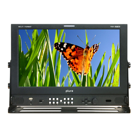
Plura MVM-124 User manual

®
Operating
Instructions
MVM Series Monitors
MVM - Series
MVM-124
MVM-140
MVM-146
MVM-147-16CH

2
1. Please read this manual thoroughly before operating the monitor.
2. Unplug monitor from the wall outlet before cleaning the LCD screen. Do not use liquid cleaners or aerosol
cleaners. Use ONLY a damp cloth provided.
3. Don’t use any unauthorized accessories not recommended by the manufacturer as they may cause
hazards.
4. Don’t operate this monitor near damp or wet surfaces.
5. Use only the recommend manufacturer mounting hardware accessories.
Slots and openings in the cabinet and the back or bottom are provided for
ventilation, and to insure reliable operation of the monitor and to protect it
from overheating, these openings must not be blocked or covered.
6. This appliance should be operated only from the type of power source
indicated on the marking label.
If you are not sure of the type of power supplied to your home, consult your
dealer or local power company. For appliance designed to operate from
battery power, refer to the operating instructions.
7. This appliance system is equipped with a 3-wire grounding type plug (a plug having a third (grounding) pin).
This plug will only fit into a grounding-type power outlet. This is a safety feature.
If you are unable to insert the plug into the outlet, contact your electrician to replace your outlet.
Do not ignore the safety purpose of the grounding plug.
8. For added protection for this product during a lightning storm, or when it is left unattended and unused for
long periods of time, unplug it from the wall outlet. This will prevent damage to the product due to lightning
and power-line surges.
9. Do not allow anything to rest on the power cord.
10. Follow all warnings and instructions marked on the appliance.
11. Do not overload wall outlets and extension cords as this can result in fire or electric shock.
12. Do not attempt to service this monitor without a qualified service personnel.
Important Safety Instructions
PORTABLE CART WARNING
(symbol provided by RETAC)

3
FCC Notice
This device complies with Part 15 of FCC Rules.
Operation is subject to the following two conditions:
(1)This device may not cause harmful interference, and (2) this device must accept any interference received,
including interference that may cause undesired operation.
To assure continued compliance, follow the attached installation instruction and do not make any unauthorized
modifications.
Note:
This equipment has been tested and found to comply with the limits for a class B digital device, pursuant to Part
15 of the FCC Rules. These limits are designed to provide reasonable protection against harmful interference in a
residential installation. This equipment generates, uses, and can radiate radio frequency energy, and if not installed
and used in accordance with the instructions, may cause harmful interference to radio communications. However,
there is no guarantee that interference will not occur in a particular installation. If this equipment does cause
harmful interference to radio or television reception, which can be determined by turning the equipment off and on,
the user is encouraged to try to correct the interference by one of the following measures:
• Reorient or relocate the receiving antenna.
• Increase the separation between the equipment and receiver.
• Connect the equipment into an outlet on a circuit different from that to which the receiver is connected.
• Consult the dealer or an experienced radio/TV technician for help.
The user may find the booklet “Something About Interference” available from FCC local regional offices helpful.
Warning:
To assure continued FCC emission limit compliance, the user must use only shielded interface cables when
connecting to host computer or peripheral devices. Also, any unauthorized changes or modifications to this
equipment could void the user’s authority to operate this device.

4
THIS EQUIPEMNT MUST BE GROUNDED
To ensure safe operation, the three-pin plug must be inserted
only into a standard three-pin power outlet which is effectively
grounded through normal household wiring. Extension cords
used with the equipment must have three cores and be
correctly wired to provide connection to the ground. Wrongly
wired extension cords are a major cause of fatalities. The
fact that the equipment operates satisfactorily does not imply
that the power outlet is grounded or that the installation is
completely safe.
For your safety, if you are in any doubt about the effective
grounding of the power outlet, please consult a qualified
electrician.
CAUTION:
THE AC RECEPTACLE (MAINS SOCKET OUTLET) SHALL
BE INSTALLED NEAR THE EQUIPMENT AND SHALL BE
EASILY ACCESSIBLE.
TO COMPLETELY DISCONNECT THIS EQUIPMENT FROM
THE AC MAINS, DISCONNECT THE POWER CORD PLUG
FROM THE AC RECEPTACLE.
The lightning flash with arrowhead symbol,
within an equilateral triangle, is intended to
alert the user to the presence of uninsulated
“dangerous voltage” within the product’s
enclosure that may be of sufficient magnitude
to constitute a risk of electric shock to persons.
The exclamation point within an equilateral
triangle is intended to alert the user to
the presence of important operating and
maintenance (servicing) instructions in the
literature accompanying the appliance.
WARNING:
TO REDUCE THE RISK OF FIRE OR SHOCK HAZARD, DO
NOT EXPOSE THIS EQUIPMENT TO RAIN OR MOISTURE.
TO REDUCE THE RISK OF FIRE OR SHOCK HAZARD,
KEEP THIS EQUIPMENT AWAY FROM ALL LIQUIDS. USE
AND STORE ONLY IN LOCATIONS WHICH ARE NOT
EXPOSED TO THE RISK OF DRIPPING OR SPLASHING
LIQUIDS, AND DO NOT PLACE ANY LIQUID CONTAINERS
ON TOP OF THE EQUIPMENT.
CAUTION:
In order to maintain adequate ventilation, do not install or
place this unit in a bookcase, built-in cabinet or any other
confined space. To prevent risk of electric shock or fire
hazard due to overheating, ensure that curtains and any
other materials do not obstruct the ventilation.
CAUTION:
TO REDUCE THE RISK OF FIRE OR SHOCK HAZARD AND
ANNOYING INTERFERENCE, USE THE RECOMMENDED
ACCESSORIES ONLY.
CAUTION:
This apparatus can be operated at a voltage in the range of
100-240 V AC.
Voltage other than 120V are not intended for U.S.A and
Canada.
CAUTION:
Operation at a voltage other than 120V AC may require
the use of a different AC plug. Please contact either a local
service center for assistance in selecting an alternate AC
plug.
Notice (U.S.A. only):
This product has a fluorescent lamp that contains a
small amount of mercury. It also contains lead in some
components. Disposal of these materials may be regulated
in your community due to environmental considerations. For
disposal or recycling information please contact your local
authorities, or the Electronics Industries Alliance:
http://www.eiae.org.
Safety Precautions
CAUTION: TO REDUCE THE ELECTRICK SHOCK.
DO NOT REMOVE COVER (OR BACK).
NO USER SERVICEABLE PARTS INSIDE.
REFER SERVICING TO QUALIFIED SERVICE PERSONNEL
RISK OF ELECTRICAL SHOCK
DO NOT OPEN
CAUTION

5
Safety Precautions continued
Information on Disposal for Users of Waste Electrical & Electronic Equipment (private households)
This symbol on the products and/or accompanying documents means that used electrical and
electronic products should not be mixed with general household waste.
For proper treatment, recovery and recycling, please take these products to designated
collection points, where they will be accepted on a free of charge basis. Alternatively, in some
countries you may be able to return your products to your local retailer upon the purchase of an
equivalent new product.
Disposing of this product correctly will help to save valuable resources and prevent any potential negative effects
on human health and the environment which could otherwise arise from inappropriate waste handling. Please
contact your local authority for further details of your nearest designated collection point.
Penalties may be applicable for incorrect disposal of this waste, in accordance with national legislation.
For business users in the European Union
If you wish to discard electrical and electronic equipment, please contact your dealer or supplier for further
information.
Information on Disposal in other Countries outside the European Union
This symbol is only valid in the European Union.
If you wish to discard this product, please contact your local authorities or dealer and ask for the correct method of
disposal.
CE NOTICE
This is Class B product. In a domestic environment this may cause radio interference in which
case the user may be required to take adequate measures.
The apparatus shall not be exposed to dripping or splashing and no objects filled with liquids,
such as vases, shall be placed on the apparatus.
Caution for AC Power Cord
FOR YOUR SAFETY PLEASE READ THE FOLLOWING TEXT CAREFULLY.
Appropriate AC Power Cord must be used in each local area.
FOR CONTINENTAL EUROPE, ETC
Not for use in the U.K.
FOR U.K. ONLY
If the plug supplied is not suitable for your socket outlet,
it should be cut off and appropriate one fitted.
FOR U.S.A. and Canada

6
Safety Precautions continued
Power
Operate unit only on the specified supply voltage.
Disconnect power cord by connector only. Do not pull on cable portion.
Do not place or drop heavy or sharp-edged objects on power cord. A damaged cord can cause fire or electrical
shock hazards. Regularly check power cord for excessive wear or damage to avoid possible re / electrical
hazards.
Grounding
Ensure unit is properly grounded at all times to prevent electrical shock hazard.
Do not ground the unit to gas lines, units, or fixtures of an explosive or dangerous nature.
Ensure power cord is firmly plugged into AC outlet.
Operation
Do not operate unit in hazardous or potentially explosive atmospheres. Doing so could result in fire, explosion, or
other dangerous results.
Do not allow liquids, metal pieces, or other foreign materials to enter the unit. Doing so could result in fire, other
hazards, or unit malfunction.
If foreign material does enter the unit, turn power off and disconnect power cord immediately. Remove material
and contact authorized service representative if damage has occurred.
Transportation
Handle with care to avoid shocks in transit. Shocks may cause malfunction. When you need to transport the unit,
use the original packing materials or alternate adequate packing.
Circuitry Access
Do not remove covers, panels, casing, or access circuitry with power applied to the unit! Turn power off and
disconnect power cord prior to removal. Internal servicing / adjustment of unit should only be performed by
qualified personnel.
Do not touch any parts / circuitry with a high heat factor.
Capacitors can retain enough electric charge to cause mild to serious shock, even after power is disconnected.
Capacitors associated with the power supply are especially hazardous. Avoid contact with any capacitors.
Unit should not be operated or stored with cover, panels, and / or casing removed. Operating unit with circuitry
exposed could result in electric shock / re hazards or unit malfunction.
Potential Hazards
If abnormal smells or noises are noticed coming from the unit, turn power off immediately and disconnect power
cord to avoid potentially hazardous conditions. If problems similar to above occur, contact authorized service
representative before attempting to again operate unit.
Consumables
The consumables used in unit must be replaced periodically. For further details on which parts are consumables
and when they should be replaced, refer to the specifications at the end of the Operation Manual. Since the
service life of the consumables varies greatly depending on the environment in which they are used, they should
be replaced at an early date. For details on replacing the consumables, contact your dealer.
Rubber Feet
If this product has come with rubber feet attached by screws, do not insert the screws again without rubber feet
after removing the rubber feet and screws. It may cause damage to the internal circuits or components of the unit.
To install the rubber feet again to the unit, do not use other than the supplied rubber feet and screws.
Important Safety Warnings

7
Upon Receipt
Unpacking
Check
Installing AC Cord
MVM units and their accessories are fully inspected and adjusted prior to shipment. Operation can be performed
immediately upon completing all required connections and operational settings.
Check your received items against the packing lists below.
Check to ensure no damage has occurred during shipment. If damage has occurred, or items are missing, inform
your supplier immediately.
Securely plug the AC cord into the AC inlet1.
Attach Retaining Clip 1 onto the the AC cord.2.
ITEM QTY REMARKS
MVM 1
AC Cord 1 set One AC cord, and one AC cord retaining clip
Operation Manual 1 set This manual (Includes Layout Editor, Live Viewer, and Web Browser
Operation Manuals, and Layout Editor Tutorial.)
Layout Editor /
Dedicated Viewer
Software
1 CD-ROM

8
Contents
1. Prior to Starting.......................................................................................................... 9
1-1. Welcome............................................................................................................ 9
1-2. About MVM ........................................................................................................ 9
MVM...........................................................................................................9

9
1. Prior to Starting
Congratulations! By purchasing MVM Multi Viewer you have entered the world of PLURA BROADCAST and its
many innovative products. Thank you for your patronage and we hope you will turn to PLURA BROADCAST
products again and again to satisfy your video and audio needs.
PLURA BROADCAST provides a wide range of products, from basic support units to complex monitoring
systems, which have been increasingly joined by products for computer video based systems. Whatever your
needs, talk to your PLURA BROADCAST representative. We will do our best to be of continuing service to you.
The MVM Multi Viewer is a four split-screen multi viewer that accepts four inputs (of HD-SDI, SD-SDI, and Analog
Composite signals), resizes the images and display on a single screen. The audio level meter display of embedded
audios of each SDI inputs is provided for monitoring the presence of audio signals. Supported video transmission
over a network also enables to remotely monitor output images. The provided layout editor allows user to freely
arrange the viewer screen layout. The MVM is most suitable for monitoring the system with mixed input of HD-SDI,
SD-SDI and analog composite signals.
• Support for mixed input of HD-SDI, SD-SDI, and Analog composite signals
• Audio level meter display for HD/SD-SDI embedded audio signals (8ch
display)
• DVI connector for high denision image output ( Not applicable when it is
integrated within MVM monitor )
• Video loss detection function
• Analog clock and Digital clock display
• Border display of two selectable colors (red and green) on each channel
frame by external tally intput
• Title display of up to 16 charactors for each input (alphanumeric and
symbol)
• Remote control: Contact inputs, RS-232C/422/485 interface and LAN
interface
• Includes layout editor for enabling users to make any changes to split-
screen patterns from a computer
• SNMP support for monitoring power supply and fan alarm status (Planned
future option)
• Redundant power supply option for ensuring the system reliability
• Video transfer at the maximum frame rate of 60fps (By the dedicated viewer
software MVM Live Viewer)
• The maximum frame rate may not be obtained due to the various factors,
such as size of transmitted image, JPEG compression rate, connected PC or
network environment.
1-1. Welcome
1-2. About MVM

10
2. Quick Start
2-1. Connection
Connect the MVM to an AC power source using the supplied accessory cord.1.
Connect the signal source device(s) to the left connector(s) of each set of 1 to 4 HD-SDI/SD-SDI/COMPOSITE 2.
INPUT connectors to supply input signal(s). The right connectors are for active through outputs which we are
not using now.
Select Quad input on the MVM monitor. 3.
Connect a PC which you are going to use to edit layout by installing the supplied Layout Editor. In the figure4.
above the shown connection is for the LAN interface that you need for Layout Editor operation.
The system requirements for the PC is shown in the section 16-2. “System Requirements” of the part 3, MVM
Layout Editor of this manual.
This chapter describes the basic operations to set up the system for your MVM multi viewer. Refer to the section
given for each operation you may need more details, if necessary.

11
2-2. Displaying Image on MVM-1XX Monitor
2-3. Connecting MVM and PC over LAN
2-3-1. PC Network Settings
2. Quick Start continued
Checking Monitor Display of Output Image1.
Turn on the power switch on the MVM front panel. When power switch is turned on, the image is displayed on
the MVM-1XX monitor. Is the image displayed on the monitor? Follow the steps given for each case
The output screen size is set to 1920 x 1200 in 60Hz at the factory.
Connect the MVM and a PC (on which you are going to install the Layout Editor) over a LAN interface. This setting
example shows the case when connecting to the MVM with the default settings. The MVM default settings are
shown below.
The PC network settings need to match that of the MVM. The procedure for making the network settings at the
PC vary depending on the OS, so refer to the OS manual for details.
Setting in Windows XP with the default Start menu setting1.
Click Start on the taskbar, open [Control Panel], and
double-click “Network Connections”. Right-click “Local
Area Connection” icon to open [Properties] window.
Double-clicking “Internet Protocol (TCP/IP)” under
the [General] tab opens the [Internet Protocol (TCP/
IP) Properties] window. Make the settings as shown
in the example below. Make a note of the settings
before changing them in case you need to return the IP
address to its original settings later.
ID ROOT
PASSWORD 0
IP address 192.168.0.1
Subnet mask length 24
Gateway 0.0.0.0
IP address for
PC
192.168.0.yyy (yyy is any number
from 2 to 254 except for the number
set for the MVM unit and the
gateway number. In this example, the
setting is yyy=200.)
Subnet mask Set to 255.255.255.0.
2. Setting in Windows XP with the Start menu setting changed to Classic
Click Start on the taskbar, select “Settings” -> “Network Connections” and then right-click the “Local Area
Connection” icon to open [Properties] window. Double-clicking “Internet Protocol (TCP/IP)” under the
[General] tab opens the [Internet Protocol (TCP/IP) Properties] window. The settings are then made in the
same way as 1) above. When the settings are completed, click OK, and then close all setting windows.

12
Install the MVM Layout Editor on the PC using the supplied CD-ROM. In this section a rough instruction for the
installation is given. For more details see section 16-4. “Installing MVM Layout Editor” in the part 3, MVM Layout
Editor of this manual.
Load the supplied Installation CD-ROM into the PC, and open the1.
CD-ROM drive. Run the file “setup.exe” to start the setup wizard.
If [.NET Framework 2.0] or [Windows Installer 3.1] is not installed on your PC, one of the screens shown2.
below is displayed. Click Accept. If either one is already installed on your PC, any of these screen is not
displayed.
When installation of [.NET Framework 2.0] is complete, the screen shown below is displayed requiring a3.
reboot. Click Yes to reboot your PC.
After the setup wizard is restarted, follow the guide to complete the installation.4.
2. Quick Start continued
2-3-2. Installing MVM Layout Editor

13
To start MVM Layout Editor, go to Start > Programs > PLURA and select “MVM Layout Editor”.1.
After the application is started the screen shown below is displayed.2.
Enter the IP address, ID and password of the MVM that you wish to connect in the MVM ID boxes at the top-3.
right of the main screen. (The factory default of the MVM is as below.)
If the entered IP address, ID, or password is not correct,
the error message as shown to the right will be displayed.
Correct the error.
Select the layout number as shown below. The selected layout is loaded and displayed in the layout editing4.
area, and the connection is established. Clicking the Display button next to the Layout No. box will display the
same layout on the monitor screen. You can edit the layout watching the display on the monitor screen.
If you are going to edit the layout, see section 19-3. “Editing Layouts” in the part 3, MVM Layout Editor of this 5.
manual for details.
2. Quick Start continued
2-3-3. Starting MVM Layout Editor
MVM ID Box
IP address: 192.168.0.1
ID: ROOT
Password: 00000

14
POWER1 switch1.
Used to turn the power unit 1 On/Off. Pressing “” side turns power on.
FULL (Full screen display button)2.
Used to set the display in full screen mode.
SPLIT (Split screen display button)3.
Used to set the display in split screen mode.
VIDEO SELECT 1 - 4 (Input switches)4.
In the full screen mode, these buttons are used to select inputs to be displayed.
In the split screen mode, these buttons are used to select the screen layout designed using the Layout Editor.
All four buttons are set to display standard 4-split screen at the factory shipment.
While displaying menus, these buttons are used to navigate menu screens.
LOCK (Operation lock button)5.
Used to disable or enable the operation from the front panel buttons.
• To unlock the operation, press and hold down the button at least 2 seconds.
While displaying menus, this button is used to confirm the settings for each menu item.
MENU (Menu button)6.
Used to open Main menu. While displaying menus, used to return to Main menu or submenu, or
exit Main menu.
• To open Main menu, press and hold down the button at least 2 seconds.
3. Panel Descriptions
3-1. Front Panel

15
HD-SDI/SD-SDI/COMPOSITE INPUT 1 - 41.
Used to input HD/SD-SDI or analog composite signals (Automatic recognision supported)
The respective right connectors are active through output connectors to output signals from left connectors to
monitors.
• Active through output (for monitors) is available for HD-SDI and SD-SDI.
• No jitter correction. The existing jitter will be carried to the active through output. The total jitter may exceed
the jitter limit of signal standard.
DVI IN2.
Used to connect a DVI-I signals
LAN(10/100BASE-T)3.
Used to control unit or arrange layouts from a PC over a LAN (Ethernet) interface. Transmitting video to a PC
is also possible.
LTC4.
Used to input time code to synchronize the analog or digital clock display. (Hour, minute and second only)
TALLY/REMOTE5.
Used for Tally input to add red or green borders to each channel frame, or remote control on selecting screen
layout by GPI inputs.
RS-232C/422/4856.
Used to connect a PC for remote control on menu operation.
HD-SDI/SD-SDI INPUT with Select OUTPUT7.
Used as two extra inputs to simulate PBM monitors functionality
Update Firmware port8.
AC IN (100-240VAC 50/60Hz)9.
Used for connecting to an AC power source using the supplied accessory cord.
3. Panel Descriptions continued
3-2. Rear Panel

16
4. Connection
4-1. System directly with PC
4-2. System with Video Transmission
IMPORTANT: To directly connect PC and MVM, use a crossover LAN cable for the
connection. To connect PC and MVM using a hub or such device, use a straight LAN cable.

17
The system with video transmission has two different network modes such as ‘Unicast mode’ and ‘Multicast
mode’. For the mode settings, see section 7-2. “SYSTEM” and 7-3. “LAN”.
The UNICAST mode using TCP/IP protocol supports the system that can provide video output to one monitor by
MVM Live Viewer.
The MULTICAST mode using IP multicast supports the system that can provide video outputs to multiple monitors
through the MVM as shown below.
4. Connection continued
4-2-1. Network Mode
4-2-1-1. UNICAST Mode
4-2-1-2. MULTICAST Mode
IMPORTANT: Due to the UDP protocol used in MULTICAST mode, the video output may not
be updated at the packet loss which occurs under the unstable network condition.

18
After the power is turned on, operation resumes from the last screen before the power was turned off. If a menu
screen was displayed when the unit was turned off, operation resumes from the status before the menu screen.
Although initialization is normally not required, you can restore the MVM factory settings by the data initialization
when the previous data is no longer needed such as after relocation or system modification. Turn on the power
while holding down the MENU button. “MEMORY CLEAR” appears on the monitor screen and the setting data
will be initialized.
To display your desired channel in full screen, press the FULL button and then press the VIDEO SELECT 1 to 4
buttons. For instance, to view channel 3 in full screen, press the FULL button and then press the SELECT 3 button.
To display split screens, press the SPLIT button. Pressing a VIDEO SELECT button while displaying split screen will
change the displayed split screen layout to another layout.
5. Operations
5-1. Operation at Startup
5-2. Data Initialization
5-3. Displaying Full Screen
5-4. Displaying Split Screens
IMPORTANT: The image distortion occurs while switching layouts. A black screen is shown
for channels with no input signals.
IMPORTANT: The image distortion occurs while switching layouts. A black screen is shown
for channels with no input signals.

19
MVM can be remotely controlled using contact inputs to the TALLY IN/REMOTE connector on the rear panel. The
connector is also provided with pins for external tally inputs that enable to display two color borders on video frames.
Compatible connector: DB-25PF-N(JAE)
Cover: DB-C4-J11-S1(JAE)
Signal standard: Make contact, TTL level negative logic pulse
Connector pin assignments (25-pin, D-sub female) Inch screws
Pin no. Function Description
1 IN1 TALLY (Red) INPUT1 TALLY border (Red) display
2 IN2 TALLY (Red) INPUT2 TALLY border (Red) display
3 IN3 TALLY (Red) INPUT3 TALLY border (Red) display
4 IN4 TALLY (Red) INPUT4 TALLY border (Red) display
5 IN1 TALLY (Green) INPUT1 TALLY border (Green) display
6 IN2 TALLY (Green) INPUT2 TALLY border (Green) display
7 IN3 TALLY (Green) INPUT3 TALLY border (Green) display
8 IN4 TALLY (Green) INPUT4 TALLY border (Green) display
9 FULL 1 INPUT1 Full screen display
10 FULL 2 INPUT2 Full screen display
11 FULL 3 INPUT3 Full screen display
12 FULL 4 INPUT4 Full screen display
13 +5V +5V output (maximum 200mA DC)
14 GND GND
15 USER1 Preset layout 1
16 USER2 Preset layout 2
17 USER3 Preset layout 3
18 USER4 Preset layout 4
19 ADJ_IN Time adjustment input
20 ADJ_OUT Time adjustment output
21 FAN_ALARM Fan alarm output
22 NC Do not use.
23 NC Do not use.
24 NC Do not use.
25 NC Do not use.
5. Operations continued
5-5. REMOTE/TALLY
IMPORTANT: The input signal pulse width should be 100ms or more. The input signal
interval should also be 100ms or more.

20
Input Connector
The gure at right depicts the MVM circuit for
each input pin.
Output Connector
The gure at right depicts the MVM circuit for each
output pin. Outputs 5V TTL level alarm signal.
Control via REMOTE connector operates the same as control from front panel buttons. Commands from both
REMOTE connector and front panel buttons are accepted at the same time.
Time adjustment made by the falling edge of the external pulse input (pulse width 100ms or more) is shown below.
When second digit displays 1 to 29 -> Correct to 0 second1.
When second digit displays 30 to 59 -> Correct to 0 second and add 1 minute2.
Outputs a pulse signal (500ms) at the interval set at the ADJUST in the [SYSTEM].
5. Operations continued
IMPORTANT: ADJ_OUT pin outputs a pulse signal at the set interval triggered by the
internal clock. ADJ_IN pin does not supply buffered output.
5-5. REMOTE/TALLY continued
5-5-1. Control using REMOTE Connector
5-5-2. ADJ_IN (External Time Adjustment Input)
5-5-3. ADJ_OUT (External Time Adjustment Output)
This manual suits for next models
3
Table of contents
Other Plura Monitor manuals

Plura
Plura PBM-4K-H Series User manual

Plura
Plura DBM-124 User manual

Plura
Plura DBM-152 User manual

Plura
Plura LCM-119-3G User manual

Plura
Plura MTD-ID User manual

Plura
Plura PBM-4K Series User manual

Plura
Plura PBM-070 User manual

Plura
Plura 3G Series User manual

Plura
Plura UD Series User manual

Plura
Plura SFP-217-3G User manual

Plura
Plura DBM-124 User manual

Plura
Plura PBM-217S User manual

Plura
Plura PBM-070 User manual

Plura
Plura PBM-217 User instructions

Plura
Plura PBM-224-4K User manual

Plura
Plura SFP-H Series User manual

Plura
Plura LCM-3G User manual

Plura
Plura PRM-3G Series User manual

Plura
Plura SFP-H Series User manual

Plura
Plura PBM-3G Series User manual