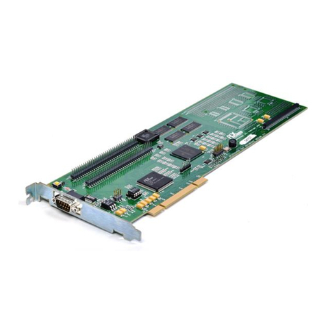
PEX 8311RDK Hardware Reference Manual, Version 0.90
© 2005 PLX Technology, Inc. All rights reserved. v
CONTENTS
1. General Information ............................................................................................................................... 1
1.1 PEX 8311 Features ......................................................................................................................... 2
1.2 PEX 8311RDK Features.................................................................................................................. 2
2. PEX 8311RDK System Architecture ...................................................................................................... 3
3. PEX 8311RDK Hardware Architecture .................................................................................................. 4
3.1 PEX 8311 PCI Express Bridge Device............................................................................................ 4
3.2 Serial EEPROM............................................................................................................................... 4
3.2.1 SPI EEPROM............................................................................................................................ 5
3.2.2 Microwire Serial EEPROM........................................................................................................ 5
3.2.2.1 Microwire Serial EEPROM Contents ............................................................................... 6
3.3 Local and PCI Express Hardware Elements ................................................................................... 7
3.3.1 Local Clock................................................................................................................................ 8
3.3.2 Synchronous Burst SRAM ........................................................................................................ 8
3.3.3 Xilinx CPLD ............................................................................................................................... 8
3.3.4 Internal Clock ............................................................................................................................ 8
3.3.5 PLX Option Module Connector ................................................................................................. 9
3.3.6 Hardware Memory Map .......................................................................................................... 10
3.4 PCI Express Interface.................................................................................................................... 10
3.4.1 RefClk ..................................................................................................................................... 10
3.4.2 PERST# .................................................................................................................................. 10
3.4.2.1 Reset Circuitry ............................................................................................................... 11
3.5 LED Indicators ............................................................................................................................... 11
3.6 PEX 8311RDK Power.................................................................................................................... 11
3.6.1 PEX 8311 Bridge Device Power ............................................................................................. 11
3.6.2 PEX 8311 Power Jumpers and Resistor options.................................................................... 12
3.7 Power Management Signaling....................................................................................................... 13
3.7.1 Wakeup ................................................................................................................................... 13
3.8 Endpoint/Root Complex operation ................................................................................................ 13
4. Mechanical Architecture....................................................................................................................... 15
4.1 Monitoring Points, Test headers, Indicators, Control, and DIP Switch Summary ......................... 16
4.1.1 Monitoring Points .................................................................................................................... 16
4.1.2 Headers................................................................................................................................... 16
4.1.2.1 Test Headers ................................................................................................................. 16
4.1.2.2 JTAG Headers ............................................................................................................... 16
4.1.3 Indicators................................................................................................................................. 17
4.1.4 Controls................................................................................................................................... 17
4.2 PEX 8311RDK Layout Information................................................................................................ 17
4.2.1 Trace Routing Design Rules ................................................................................................... 17
4.2.2 Power Decoupling ................................................................................................................... 17
4.2.3 PCB Stackup........................................................................................................................... 18
4.3 MidBus LAI Footprints ................................................................................................................... 19
4.4 Prototyping Area............................................................................................................................ 19
4.4.1 Surface Mount Footprints........................................................................................................19
4.4.2 Uncommitted FPGA footprint .................................................................................................. 20
4.4.2.1 Uncommitted FPGA connections .................................................................................. 20
4.4.2.2 Uncommitted FPGA to PEX 8311 local bus .................................................................. 20
4.4.2.3 Programming the uncommitted FPGA........................................................................... 24
4.4.2.3.1 Programming the FPGA through the JTAG interface................................................ 24
4.4.2.3.2 Programming the FPGA through the GPIO............................................................... 27
4.4.2.3.3 Programming the uncommitted FPGA from the configuration PROM....................... 28
4.4.2.4 Uncommitted FPGA power supplies.............................................................................. 29
4.4.2.5 Uncommitted FPGA Pull-ups/downs ............................................................................. 30
4.4.2.6 Increasing the number of unused uncommitted FPGA I/O ........................................... 30
5. RDK Mode Configuration ..................................................................................................................... 31
6. Examples of Testing the OnBoard 32Kx32 SBSRAM with PLXMon ................................................... 33
7. CPLD Verilog Code.............................................................................................................................. 35
