PNI SAFE HOUSE 200 User manual

PNI SAFE HOUSE 200
KIT SENZOR GAZ SI ELECTROVALVA 3/4"
Manual de utilizare
User manual
Használati útmutató


2
RO
Acest produs este un detector destinat identificarii scurgerilor de gaz cu
fiabilitate ridicata ce se monteaza pe perete. Produsul este destinat folosirii
in locuinte, vile, magazine, pensiuni de familie etc.
Introducere
Descriere produs
LED indicator
pornit / oprit
LED functii
Buton teste
Valva electromagnetica
Buton pentru actionare manuala
Cablu conexiune cu detectorul de gaz

3
Caracteristici principale
- Senzor cu fiabilitate ridicata
- Resetare automata dupa alarma
- Procesare printr-o unitate de microcontrol
- Detectare gaze naturale, gaz metan, GPL, CO etc.
- Special pentru montajul pe perete
Specificatii tehnice
Tensiune de alimentare
230V
Consum curent in stand-by
≤ 90mA
Consum curent in alarma
≤ 100mA
Consum max
3W (la 230V)
Timp amorsare
aprox. 180 secunde
Nivel alarma
10±5 %LEL (Lower Explosive Limit);
0.5±0.25 (VOL%)
Indicator alarma
flash LED rosu
Indicator eroare
LED rosu si sunet prelungit
Nivel sunet
≥ 85dB/m
Temperatura de functionare
0 0
-25 C ~ +50 C
Umiditate
≤ 95% RH
Tip montaj
pe perete
Dimensiuni senzor
115 x 72 x 46 mm
MANUAL DE UTILIZARE SENZOR
RO

4
1. Mai intai identificati daca gazul de la sursa este mai greu sau mai usor
decat aerul. Gaze mai grele decat aerul: GPL etc. Gaze mai usoare decat
aerul: gaz natural, gaz metan etc.
2. In functie de greutatea gazului, alegeti amplasarea corecta a detectorului
de gaz. In cazul in care gazul este mai greu decat aerul, pozitionati
detectorul de gaz la o inaltime de 0,3 - 1,0 m fata de podea, pe o raza de
max. 1,5 m de sursa de gaz. In cazul in care gazul este mai usor decat aerul,
pozitionati detectorul de gaz la o inaltime de 0,3 - 1,0 m fata de tavan, pe o
raza de max. 1,5 m de sursa de gaz.
3. Fixati bine suruburile in perete, dupa care pozitionati detectorul de gaz.
4. Evitati sa instalati detectorul de gaz in apropierea urmatoarelor surse:
flux direct de aer cauzat de vant, ventilatoare, usi sau ferestre deschise,
surse de abur, vapori de ulei etc.
5. Orice instalare a unui dispozitiv cu fir trebuie sa respecte legile nationale
in vigoare. Firele trebuie sa aiba dimensiunea si culoarea corecte, pentru a
evita legaturi eronate. O conexiune gresita a firelor poate avea
repercursiuni in caz de alarma cauzata de scurgeri de gaz.
Detector gaz
Diametru:
3M
Aragaz FLOOR
TAVAN
PODEA
Instructiuni de instalare
RO

5
Conexiuni
Instructiuni de folosire
P1
Intrare alimentare
P2 SIG1 SIG2
Electrovalva
Detectorul de gaz poate fi folosit independent sau in legatura cu o
electrovalva .
Folosirea detectorului de gaz independent
1. Alegeti locul potrivit instalarii detectorului de gaz. Urmati instructiunile de
instalare.
2. Alimentati detectorul de gaz la o sursa AC 220V. LED-ul verde va clipi o
data pe secunda timp de 3 minute, timp necesar amorsarii senzorului. Dupa
amorsarea senzorului, detectorul va emite un sunet scurt pentru a atentiona
ca a intrat in starea normala de functionare. Ledul va continua sa clipeasca.
Folosirea detectorului de gaz impreuna cu o electrovalva
1. Alegeti locul potrivit instalarii detectorului de gaz. Urmati instructiunile de
instalare.
2. Alimentati detectorul de gaz la o sursa 220V. LED-ul verde va clipi o data
pe secunda timp de 3 minute, timp necesar amorsarii senzorului. Dupa
amorsarea senzorului, detectorul va emite un sunet scurt pentru a atentiona
ca a intrat in starea normala de functionare. Ledul va continua sa clipeasca.
3. Daca senzorul detecteaza o scurgere de gaz, LED-ul rosu clipeste, in
timp ce sirena incorporata emite un sunet de alarma repetitiv “Di ... Di”.
Daca detectorul este legat de o electrovalva va determina acest dispozitiv
sa opreasca furnizarea cu gaz. Detectorul de gaz se va intoarce la starea
initiala de functionare dupa dispersarea gazului sau dupa repornirea
detectorului.
4. Daca sirena emite un sunet lung, iar LED-ul rosu este aprins - indica o
eroare a senzorului intern. Intrerupeti alimentarea si contactati un centru
service.
5. Daca detectorul functioneaza in mod discordant, intrerupeti alimentarea
la curent si reinitiati procedura de punere in functiune. Daca problema
persista, contactati un centru service.
RO

6
Test
Intretinere
Proceduri in caz de alarma
Informatii LED
Pentru a testa un detector de gaz instalat, puteti raspandi in aer un pic de
gaz la o distanta de 5 cm de fantele pentru gaz ale detectorului, folosind o
bricheta. Testarea frecventa poate cauza reducerea sensibilitatii
senzorului. Detectorul va intrerupe alarma si va reintra in modul normal de
functionare, dupa ce densitatea de gaz va scadea sub nivelul de alarma.
Utilizatorul ar trebui sa curete o data la trei luni fantele de gaz ale
detectorului si ar trebui sa testeze detectorul dupa curatare ca sa se asigure
ca nu a patruns substanta de curatat la senzor.
Detectorul de gaz intra in starea de alarma daca densitatea gazului din
incapere depaseste nivelul minim de alarma. Procedati dupa cum urmeaza:
1. Inchideti imediat valva de alimentare cu gaz
2. Deschideti fereastra si lasati sa patrunda rapid aer in incapere
3. Inchideti orice sursa de foc si nu folositi nimic care ar putea cauza un foc,
de exemplu brichete, chibrituri etc.
4. Evitati sa aprindeti orice echipament electric
5. Incercati sa gasiti locul exact unde are loc scurgere de gaz si anuntati
imediat institutiile specializate sau o persoana calificata
LED rosu intermitent
scurgere de gaz
LED rosu aprins
eroare senzor
LED verde intermitent/0.5s aprins 0.5s stins
amorsarea senzorului
RO
Avertizari
1. Detectorul de gaz trebuie sa fie instalat si conectat in mod corect. Nu
poate functiona daca nu este alimentat la o sursa de curent.
2. Intretineti in mod regulat detectorul conform indicatiilor.
3. Testati functionarea detectorului la fiecare sase luni.
4.Din diferite motive, cum ar fi schimbarea conditiilor de mediu, intreruperea
curentului electric sau actionarea frauduloasa asupra sistemului electronic,
produsul ar putea sa nu functioneze corespunzator. Utilizatorul este sfatuit
sa ia toate masurile de precautie privind siguranta sa si a bunurilor sale.

7
Electrovalva ofera o solutie de siguranta, oprind gazul in caz de urgenta prin
inchiderea ventilului. Electrovalva poate fi conectata la un senzor de gaz, la
un circuit de alarma pentru incendiu sau alte tipuri de senzori de gaz (cum ar
fi wireless) pentru sistarea furnizarii gazului in caz de urgenta. Electrovalva
prezinta un sistem de inchidere automat, atunci cand sunt detectate
tensiuni de intrare de 9-12 V. Dupa inchidere, deschiderea acesteia se face
manual prin ridicarea butonului rosu.
MANUAL DE UTILIZARE ELECTROVALVA
Mod de inchidere: impuls de
curent sau manual
Tensiune: DC 9 ~ 12 V (Impuls)
Material: aliaj de alama
Descarcare condensatori: 1000µF
Material etansare: cauciuc NBR
Timp inchidere: < 1 secunda
T. de functionare: -10ºC +50 ºC
Lungime cablu: 0.4 m
P. max: 100 kPa
Conexiune: G3/4” FI
Pornire: manuala
Date tehnice
RO

8
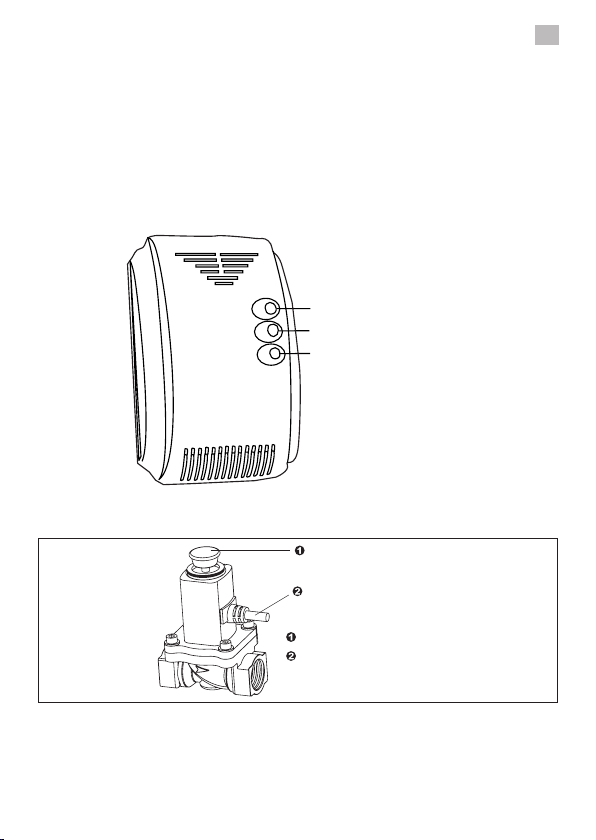
1. Electrovalva poate fi actionata pentru inchidere in doua moduri:
a) Un impuls electric de 1 secunda (9 - 12V c.c.)
b) Prin apasarea butonului rosu (mai intai trebuie sa indepartati capacul
protector din plastic).
Dupa aceasta operatiune, electrovalva ramane inchisa.
NOTA: Capacul protector trebuie sa ramana pus pe tot timpul folosirii
electrovalvei.
2. Atunci cand electrovalva este inchisa, trageti de butonul rosu vertical in
sus pentru a debloca electrovalva. Electrovalva va ramane deschisa.
3. Electrovalva se va inchide automat atunci cand primeste semnal de
intrare de la senzor. Daca acest lucru nu se intampla, contactati furnizorul
sau producatorul pentru reparatii.
4. Dupa inchiderea electrovalvei se va realiza o inspectie a instalatiei de
gaz. Umblati cu prudenta atunci cand electrovalva trebuie repornita.
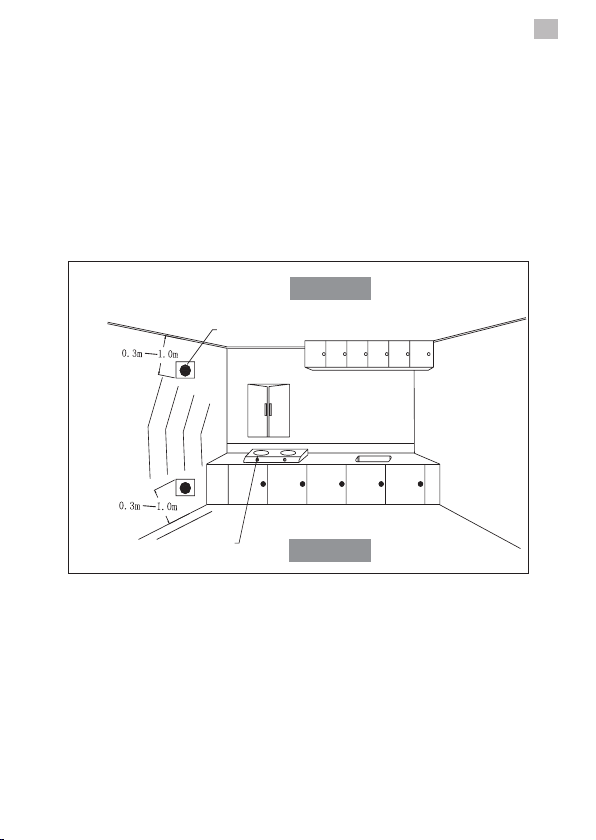
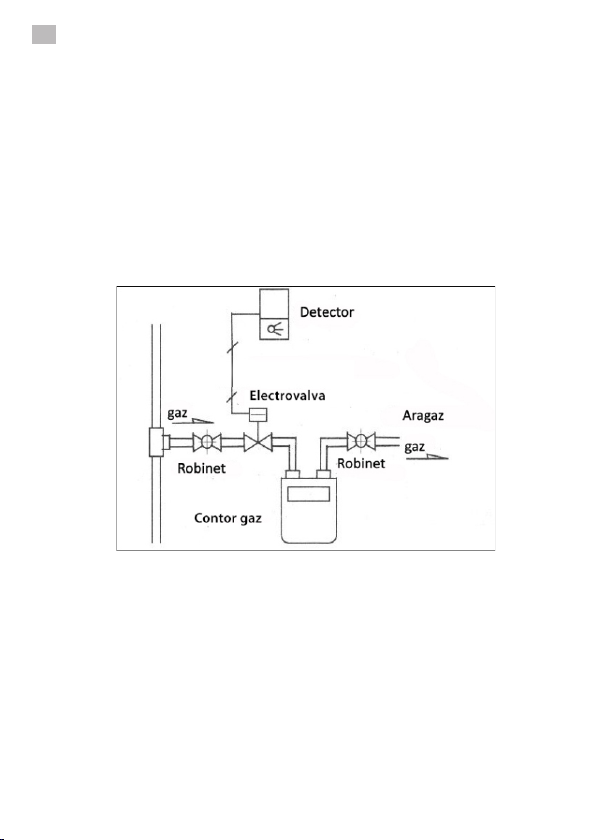
1. Electrovalva se va instala numai de catre personal calificat.
2. Electrovalva trebuie instalata dupa robinetul principal de gaz interior.
3. Electrovalva trebuie instalata in directia fluxului de gaz marcata pe
supapa electrovalvei. Bobina nu trebuie montata cu fata in jos. Electrovalva
poate fi instalata pe orizontala sau verticala.
4. Firele de control ale electrovalvei trebuie conectate corect. Firul alb este
pozitiv, iar negru este negativ. Realizarea unei conexiuni incorecte poate
duce la risc de scurtcuit.
5. In timpul lucrarilor de mentenanta la teava de gaz, cum ar fi curatarea tevii
cu presiune, electrovalva trebuie demontata pentru a evita defectiunile
acesteia.
6. In timpul testelor de presiune, electrovalva trebuie deschisa.
7. Butonul de deschidere al electrovalvei poate fi tras vertical in sus atunci
cand presiunile sunt egale (admisie si evacuare).
8. Polaritatea inversata si tensiunea gresita pot deteriora bobina
electromagnetica a electrovalvei.
Instructiuni de utilizareInstructiuni de utilizare
Recomandari pentru instalare
RO

9
9. Garantia noastra nu include defectiuni ale electrovalvei datorate unei
instalari defectuoase sau pierderea partilor componente.
10. Se recomanda instalarea cu senzorul de gaz din kit care se conecteaza
cu electrovalva plug & play (mufa in mufa), fara alte modificari.
1. In cazul in care suruburile si saibele intra in contact cu apa sau chimicale,
este necesara stergerea acestora pentru prevenirea coroziunii;
2.In cazul in care produsul este instalat total sau partial in afara, este
recomandata protectia impotriva apei;
3.Capacul transparent are rolul de protectie impotriva actionarii
accidentale a butonului rosu de actionare.
Conectarea senzorul de gaz cu electrovalva se face mufa in mufa (plug &
play) fara alte ajustari, insa ambele produse se pot adapta si pentru alte
aparate de tip electrovalva, respectiv senzor daca se schimba sistemul de
mufare.
A. Firul negru se conecteaza la “-” (masa) de la “-“ electrovalvei.
B. Firul alb se conecteaza la “+“ (sarcina) de la “+” electrovalvei.
C. Alimentarea cu energie se face la 230V c.c.
Precautii
Conectarea senzorului cu electrovalva
RO

10
Recomandari pentru cablu
Intretinere
1. Cablu: bifilar, 2 x 0.3 mm² sau mai mare
2. Lungimea cablului < 20 metri
Trebuie efectuata regulat o inspectie a aparatului. In caz de defect,
contactati furnizorul pentru reparatii imediate.
RO


12
EN
The product is wall mounted gas detector with high stability (hereinafter
called detector). It is used for detecting leaking gas. Advanced
semiconductor sensor is adopted to ensure high stability and long life. It is
convenient for mounting. The product is suitable for the safety of residential
house, villas, hotels, markets, boarding house etc.
Product introduction
Product profile
Working LED
Power LED
Test button
Electromagnetism valve
Manual pole
Control line
(connect with detector)

13
Main features
- High reliability sensor
- Auto reset after alarm
- MCU Processing adopted
- Auto detect sensor failure
- Induced gas - natural gas / LPG
- SMT design, high stability
Technical specification
Operating voltage
AC 230V
Static current
≤ 90mA
Alarm current
≤ 100mA
Rating power
≤ 3W (la AC 230V)
Warm-up time
about 180 s
Alarm level
10±5 (%LEL); 0.5±0.25 (VOL%)
Alarm indicator
red LED flash
Failure indicator
red LED on & beeper long-buzz
Sound level
≥ 85dB/m
Operating temperature
0 0
-25 C ~ +50 C
Environment humidity
≤ 95% RH
Installation mode
wall mounted
Outline size
115 x 72 x 41 mm

14
1. Please confirm the induced gas is heavier than air or lighter than air. The
gas is heavier than air: LPG etc. The gas is lighter than air: natural gas,
marsh gas and etc.
2. Choosing the suitable position to install the detector according to the gas
specific gravity. Detecting the gas heavier than air: Installation height from
floor: 0.3-1.0m, Semi-diameter to gas source: <1.5m; Detecting the gas
lighter than air: Installation height from ceiling: 0.3-1.0m, Semi-diameter to
gas source: <1.5m
3. Fix the screw into the wall firmly, then hang the detector.
4. Avoid installing the detector close to the following sources of interference:
direct air flow from vents, fans, doors, windows, sources of steam, oil vapor,
etc.
5. All wires installation must accord with the national and local effective laws
and criteria. The wires must have the suitable size and colorful marks for
avoiding connecting error. And unsuitable connection of wires will result in
the alarm error while gas leaking happened.
Detector
Diameter:
3M
Gas oven FLOOR
CEILING
FLOOR
Installation
EN

15
Terminal block figure
Operating instructions
P1
Power input
P2 SIG1 SIG2
Valve
The gas detector can be used independently or with wired networks
output functions.
Independently
1. Choosing a suitable position to install the Detector according to the
Installation
2. With AC 220V power supply, the green LED flashes once a second for
about 3 minutes continuously, that runs the inside sensor (warm-up state).
After doing that the green LED lights, that means the detector comes into
normal working state.
In wired network
1.Choosing a suitable position to install the detector according to the
Installation
2. With AC 220V power supply, the green LED flashes once a second for
about 3 minutes continuously, that runs the inside sensor (warm-up state).
After doing that, the green LED lights, that means the detector comes into
normal working state.
3. While detecting the gas leaking, the red LED flashes, the buzzer sends
out the alarm sound "Di...Di", and output the network signal. If the detector is
connected with valve or manipulator, it will drive them to shut off the gas
pipeline supply. The detector will resume to the detecting state after the gas
dispersed.
4. The buzzer long beeps and the red LED ON means the inside sensor
failure. Please cut off the power, and contact the After Service Center.
5. If the detector runs disorderly, cut the power off and rerun again. If still in
wrong, please contact the After Service Center.

16
Test
Maintenance
Emergency alarm treatment
LED information
To test the installed detector while using independently or in network, you
can give some gas around in distance of 5 cm to the gas convection holes by
using un-ignition lighter.Testing frequently may result in reducing the
sensitivity of the detector.The Detector will stop alarm and resume to the
detecting state while the gas density reduced to lower than the alarm
level.
Suggestion: the user must brush and clean the gas convection holes with a
little cleanser every three months, and must retest the detector after
cleaning for preventing the cleanser into the detector.
The detector alarms while the gas density in air exceed the alarm level. The
relative treatments as below:
1. Shut down the tube valve right away.
2. Open the window and make the air flow rapidly.
3. Extinguish all fire sources and do not use anything can make fire, e.g.
lighters, matches, etc.
4. Avoiding open or close the power all kinds of electric equipment.
5. Check the reason of gas leaking, and notice the relative departments and
professional persons in time.
RED LED FLASH
GAS LEAKING
RED LED ON
SENSOR FAILURE
GREEN LED Flash/ 0.5S on
WARM-UP SENSOR
Notice
1. The detector must be installed and connected correctly. It can not work if
without the power supply orderly.
2. Please periodically maintenance according to the directions.
3. The detector must have a test every half a year.
4.For various reasons, including, but not limited to, changes in
environmental conditions, electric or electronic disruptions and tampering,
the Product may not perform as expected. The user is advised to take all
necessary precautions for his/her safety and the protection of his/her
property.
EN

17
The valve offers a safe solution stopping the gas in an emergency. It can be
connected to a gas sensor for gas leak detection, a fire alarm circuit or other
variants of gas sensors (such as wireless) for gas supply interruption
(manually or automatically) in emergency. The valve features a locking
system automatically detected when input voltages of 9-12 V. After closing,
opening it is done manually by lifting vertically the red button. This function
will ensure safety when there is a defect of the gas.
ELECTROMAGNETISM VALVE - INSTRUCTIONS
Detected gas type: natural gas
Locking mode: current pulse or
manual
Material: Brass alloy
Power voltage: DC 9 ~ 12 V
(Impulse)
Sealing material: rubber NBR
Capacitor discharge: 1000µF
Operating temperature: -10ºC
+50 ºC
Closing time: < 1 sec.
P max: 100 kPa
Cable length: 0.4 m
Conection: G3/4” FI
Manual activation
Technical details
Protective cover Reset button
Operating element
Cable
Brass element

18
1. The valve can be operated in two modes to close:
a) An electrical impulse 1 second (9 - 12V c.c.)
b) By pressing the red button (you must first remove the protective plastic
cover).
After this operation, the valve remains closed.
NOTE: The protective cover must always stay in place during the valve use.
2. When the valve is closed, pull the red button vertically upwards to unlock
it. The valve ramains open.
NOTE: The button can be operated by pulling vertically upwards if the gas
pressure on both sides (intake and exhaust) is not balanced. Steps shall be
taken to ensure that these two pressures are balanced; only then can rise
up vertically button.
NOTE: Try not to force this button to not damage it.
3. The valve will close automatically when it receives input from the sensor. If
this does not happen, contact the supplier or manufacturer.
4. After closing the valve, an inspection of the gas system should be made.
Use caution when the valve must be restarted.
1. The valve will be installed only by qualified personnel.
2. The valve should be installed after the main interior gas.
3. The valve must be installed in the gas flow direction marked on it. The coil
should not be installed upside down. The valve can be installed horizontally
or vertically.
4. The control wires must be connected correctly. White wire is positive and
black is negative. Achieving incorrect connections may result in risk of short
circuit.
5. During maintenance work on the gas pipe, such as pipe cleaning with
pressure, the valve should be removed to avoid its failures.
6. During pressure testing, the valve should be open.
7. The opening button of the valve can be pulled up vertically when
pressures are equal (intake and exhaust).
8. Reverse polarity and wrong voltage can damage the valve’s
electromagnetic coil.
Instructions for use
Recommendations for installation
EN

19
9. Our guarantee does not cover damage due to improper installation or
component parts loss.
10. We recommend installing the gas sensor with the plug & play valve. No
changes needed.
1.If the screws and washers come in contact with water or chemicals, it is
necessary to clean them to prevent corrosion;
2.If the product is installed fully or partially outside, it is recommended to
protect it against water;
3. The transparent cover is designed to protect against accidental actuation
of the red button.
Connect valve and gas sensor through plug in jack (plug & play) without any
adjustments. Both products can be adapted for other valve type devices or
sensor if you change sleeve system.
A. Black wire connects to “-”
B. White wire connects to “+“
C. The power supply is 230V dc
Cautions
Connecting the gas detector with the electromagnetism valve
Other manuals for SAFE HOUSE 200
1
Table of contents
Languages:
Other PNI Gas Detector manuals

PNI
PNI Safe House Dual Gas 250LR User manual

PNI
PNI SafeHouse HS110 User manual

PNI
PNI SAFE HOUSE 200 User manual

PNI
PNI GD-01 User manual

PNI
PNI GD-01 User manual

PNI
PNI SafeHouse HS110 User manual

PNI
PNI GD-01 User manual

PNI
PNI JL269 User manual

PNI
PNI Safe House Smart Gas 300 WiFi User manual

PNI
PNI GD-01 User manual
Popular Gas Detector manuals by other brands

Honeywell
Honeywell Signalpoint Pro Technical manual

Riken Keiki
Riken Keiki SD-1D-AS operating manual

Emerson
Emerson MRLDS 450 user guide

Control Equipment
Control Equipment GX-3R Quick reference guide

Honeywell
Honeywell Searchline Excel Open-Path Technical handbook

FORENSICS DETECTORS
FORENSICS DETECTORS FD-90E-RED Operation manual