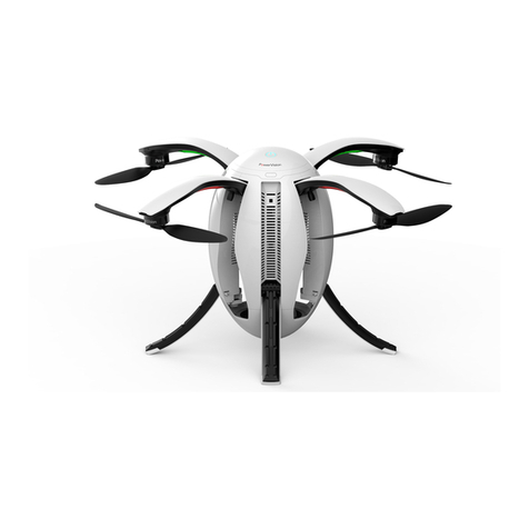
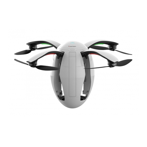
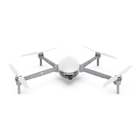
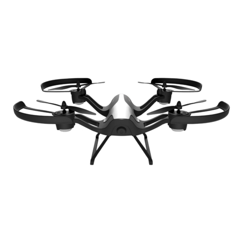
PowerVision PowerEgg User manual

PowerEgg
User Manual
PEGF-E1
.0
PowerVision

Product Overview
....................................................................................................................
1
lntroduction...........
...
.
...
..........................
...
.
...
..........
...
.
...
.........
...
..............
...
.
...
..............
...
.........
..
l
Feature Highlights
...
.
...
..........................
...
.
...
..........
...
.
...
.........
...
.
....
.........
...
.
...
.........
....
.
...
.........
..
l
Components
of
the
Aircraft.....................................................................................................
..
2
Components
of
Remote Controller
....
.
...
.
...
...........................................
...
.
...
..........................
..
3
Preparation
of
the
Aircraft.........................................................................................................6
Preparation
of
Remote Controller and Base Station.............................................................8
Aircraft
......
.
...
.
...
.
.......
.
........
.
.......
.
...
.
...
.
........
.
...
.
...
.
.......
.
...
.
....
.
.......
.
...
.
...
.
.......
.
....
.
...
.
.......
.
...
.
...
.
........
.
..
9
Overview
of
the
Aircraft.............................................................................................................9
Flight
Modes
.........
...
.
...
.........
....
.
...
.........
...
.
...
..........
...
.
...
.........
...
.
....
.........
...
.
...
.........
....
.
...
.........
..
9
Accessibility
...
............................................................................................................................10
Aircraft Status lndicator...........................................................................................................14
Description
of
Aircraft Status lndicator......
..
..
..
..........
..
....
............................
..
..................
..
...
15
Visual Positioning System........................................................................................................16
Propellers........
...
.
...
..........
...
.
...
.........
...
.
...
..........
...
.
...
.........
....
.
...
.........
...
.
...
..........
...
.
...
.........
...
.
...
18
Intelligent Battery.....................................................................................................................18
Remote Controller
.........
.
...
.
.......
.
...
.
............
.
...
.
...
.
.......
.
........
.
.......
.
...
.
...
.
............
.
...
.
.......
.
...
.
...
23
Overview
of
Standard Controller.........................................................................................
23
Operation
of
Standard Controller.......................................................................................24
Standard Controller Turn
On/Off.
................................................................................24
Standard Controller Charge
..
..
.......
..
..
..
...
..
......
..
.......
..
.......
..
..
..
..
..
.......
..
.......
..
........
...
..
..
25
Standard Controller Control
..
..
..
..
...
..
..
..
..
..
...
..
..
..
..
..
...
..
..
..
..
..
...
..
..
..
..
..
...
..
..
..
..
...
..
..
..
..
..
...
..
25
Standard Remote Controller lndicator.
..
..
..
...
..
......
..
...
..
..
..
.......
..
..
..
...
........
..
...
.
...
..
........
...
..
..
27
Maestro
rM
Overview.
...
..
..
..
..
...
..
..
..
..
...
..
..
..
..
..
...
..
..
..
..
..
...
..
..
..
..
..
...
..
..
..
..
..
...
..
..
..
..
..
...
..
..
..
..
...
..
..
..
28
MaestroTM Operation
..
..
..
..
...
..
......
..
...
..
..
..
.......
..
..
..
..
..
.......
..
...
.
...
..
......
...
..
..
..
..
...
.
...
..
..
..
..
...
......
28
MaestroTM Turn
On/Off
..
..
..
...
......
..
..
...
..
..
......
...
..
..
..
..
.......
..
..
..
..
...
......
...
.
...
..
..
.......
..
..
..
..
...
.29
Maestro
TM Charge.
..
..
..
...
..
......
..
...
..
..
..
.......
..
......
...
......
..
..
...
..
..
......
...
......
..
.......
..
..
..
..
...
......29
Maestro
TM Control.
..
..
..
...
..
......
..
...
..
..
..
.......
..
..
..
..
..
.......
..
...
.
...
..
.......
..
..
..
..
..
.......
..
..
..
...
........
30
MaestroTM lndicator......
..
..
..
...
..
........
...
..
..
..
.......
..
..
..
...
........
..
.......
..
........
...
..
..
..
.......
..
..
..
...
........
32
Base Station.
..
...
..
..
..
..
.
..
..
..
..
..
.....
..
..
..
..
..
.....
..
..
..
...
..
..
..
..
..
...
..
..
..
..
..
...
..
..
..
..
..
...
..
..
..
..
..
...
..
..
..
.......
..
..
..
33
Overview
of
Base
Station.
...
..
..
..
......
...
..
..
..
...
..
..
..
..
..
..
...
..
..
..
..
...
..
..
..
..
...
.
...
..
..
..
..
...
..
..
..
..
..
...
..
..
..
..
33
Operation
of
Base
Station
..
..
..
......
...
..
..
..
..
.......
..
..
..
..
...
......
..
..
...
..
..
......
...
..
..
..
..
.......
..
..
..
..
...
......
33
Turn
On/Off
....
.
..
..
......
...
......
..
.......
..
......
...
......
..
..
.
....
..
......
...
......
..
.......
..
..
..
...
..
......
...
......
..
...
33
Connection.
..
..
.......
..
..
..
...
..
......
..
...
..
..
..
.......
..
..
..
..
..
.......
..
...
.
...
..
.......
..
..
..
..
..
.......
..
..
..
...
........
33
Frequency Match
of
Base
Station
..
..
.......
..
..
..
..
..
.......
..
...
.
...
..
.......
..
..
..
..
..
.......
..
..
..
...
..
......
34
Unbind
..
...
..
..
..
..
.......
..
..
..
...
..
......
..
...
..
..
..
.......
..
..
..
..
..
.......
..
...
.
...
..
.......
..
..
..
..
..
.......
..
..
..
..
..
.......
35
Charge
..
...
..
..
..
..
...
..
..
..
..
..
..
...
......
..
..
...
..
..
..
..
...
..
..
..
..
...
..
..
..
..
..
...
..
..
......
...
..
..
..
..
...
.
...
..
..
..
..
...
......
36
Indicator ...
..
..
..
.......
..
..
..
..
...
.
...
..
...
.
...
..
..
......
...
..
..
..
...
.
..
...
..
..
...
..
..
..
...
.
...
..
..
..
..
.......
..
..
..
..
...
.
...
..
36
Gimbal
Camera
..
..
..
...
..
..
..
..
..
...
..
..
..
..
...
..
..
..
..
..
..
...
..
..
..
..
...
..
..
..
..
..
...
..
..
..
..
..
...
..
..
..
..
...
..
..
..
..
..
..
...
..
..
..
37
Overview
of
Gimbal Camera
..
..
..
..
..
...
..
..
..
...
.
...
..
..
..
..
...
..
..
..
..
...
.
...
..
..
..
...
..
..
..
..
..
...
..
..
..
..
..
...
..
..
..
..
37
Gimbal Usage
..
..
..
..
...
..
..
..
..
..
...
..
..
..
..
..
...
..
..
..
..
..
...
..
..
..
..
..
...
..
..
..
...
.
...
..
..
..
..
...
..
..
..
..
...
.
...
..
..
..
...
..
..
..
..
37
Introduction
to
Vision+
..
..
..
..
..
..
..
..
..
........
..
..
..
..
..
..
..
..
..
......
....
..
..
..
..
..
..
..
..
........
..
..
..
..
..
..
..
..
....
..
38
Product Description.
..
..
..
..
..
...
..
.
....
.
...
..
..
..
..
..
..
...
..
..
..
..
...
.
...
..
..
...
..
..
..
..
...
.
...
..
..
..
..
...
..
..
..
..
..
..
...
.
...
..
38
Vision+ Features
..
..
....
.
..
..
..
...
..
..
......
...
..
..
..
..
..
..
...
..
..
..
..
...
......
..
..
...
..
..
......
...
..
..
..
..
...
..
..
..
..
..
..
...
......
38
Homepage
..
..
..
.......
..
..
..
...
..
......
..
...
..
..
..
.......
..
..
..
..
...
......
..
...
.
...
..
.......
..
..
..
..
..
.......
..
..
..
..
..
.......
38
Display
of
Relevant Parameters.
..
..
..
.......
..
..
..
..
..
.......
..
...
.
...
..
.......
..
..
..
..
..
.......
..
..
..
...
..
......40
One-click Return Home.
..
........
...
..
..
..
.......
..
..
..
..
..
.......
..
...
.
...
..
.......
..
..
..
..
..
.......
..
..
..
...
........
41
Route Planning......
..
..
..
...
..
......
..
...
..
..
..
.......
..
......
...
......
..
..
...
..
..
......
...
......
..
.......
..
..
..
..
...
......
41
Flight Modes.
..
..
......
.
..
..
..
...
..
.........
..
..
..
..
..
.......
..
..
..
..
..
.
...
.
..
..
..
...
..
..
..
.
......
..
..
..
..
....
.
..
..
..
...
..
..
..
42
Return Point Settings
..
...
..
..
..
..
...
..
..
..
..
..
..
...
..
..
..
..
...
..
..
..
..
..
...
..
..
..
..
..
...
..
..
..
..
...
..
..
..
..
..
..
...
..
..
..
42
Electronic Fencing.
..
..
..
...
..
..
..
..
..
...
..
..
..
..
...
..
..
..
..
..
...
..
..
..
..
..
...
..
..
..
..
..
...
..
..
..
..
..
...
..
..
..
..
.....
..
..
..
43
Positioning
..
..
..
...
.
...
..
..
..
...
..
..
..
..
..
...
..
..
..
...
.
...
..
..
..
..
..
...
..
..
..
.......
..
..
..
..
...
..
..
..
..
...
.
...
..
..
..
...
..
..
..
..
43

Layer Switch..
...
.
..
.
..
..
..
.
..
.
...
..
..
..
..
..
..
.
..
..
..
.
..
..
..
.
...
..
...
..
..
..
..
..
.
..
..
..
..
..
..
..
...
..
..
..
..
...
..
..
..
..
..
...
..
...
.
..
.
43
Map
Direction Lock
......
..
..
..
..
.......
..
..
..
..
...
......
..
...
.
...
..
.......
..
..
..
..
..
.......
..
..
..
..
...
......
..
...
..
..
..
.....
43
Image Transmission
...
..
....
.
..
..
.......
..
..
..
..
..
.......
..
.......
..
.......
..
...
.
..
..
.......
..
..
.
....
........
..
.......
..
.....
43
Taking Photos/Shooting
..
..
..
.......
..
..
..
..
..
.......
..
...
.
...
..
.......
..
..
..
..
..
.......
..
..
..
...
........
..
...
.
...
..
.....44
Settings.....
..
..
..
..
..
.......
..
...
..
..
..
......
...
..
..
..
..
.......
..
..
...
..
..
.......
..
..
..
..
..
.......
..
..
..
..
..
.......
..
..
..
...
..
.....44
Media
.
..
..
..
..
..
...
..
..
..
..
...
..
..
..
..
.....
..
..
..
..
..
...
..
..
..
..
..
...
..
..
..
..
.......
..
..
..
..
.
..
..
..
..
..
..
..
.
..
..
..
.....
..
..
..
..
..
.
..
..
..
..
...
..
...
47
Service.
..
.
...
..
..
...
..
..
......
...
..
..
..
..
...
.
...
..
..
..
..
...
......
..
..
...
..
..
...
.
..
...
..
..
..
...
..
.
...
..
..
...
..
..
......
...
..
..
..
..
...
.
...
..
..
..
..
..
47
Flight
...
.
...
..
.......
..
..
..
..
..
.......
..
..
..
...
..
.......
..
..
..
..
..
.......
..
..
..
..
..
.......
..
...
.
...
..
.......
..
..
..
..
..
.......
..
..
..
..
...
......
..
...
48
Flight Restrictions and Special Area Limited Flight.
..
.......
..
..
..
..
..
.......
..
.......
..
........
...
..
..
..
....
.48
Flight Environment Requirements
...
..
..
..
..
..
.......
..
...
.
...
..
.......
..
..
..
..
..
.......
..
..
..
...
..
......
..
...
..
..
..
....
.49
Connection
of
Aircraft, Remote Controller and Vision+
...
..
..
..
..
...
......
..
..
...
..
..
......
...
..
..
..
..
....
.49
Compass Calibration.
..
..
..
.
..
.
...
.
...
..
...
.
..
..
...
..
.
..
..
..
.
...
..
...
..
..
..
..
..
...
..
..
..
..
..
...
..
..
..
..
..
..
.
..
..
..
..
..
...
..
..
..
..
.
52
Start/Stop The
Motor
..
..
..
...
.
...
..
..
..
...
..
..
..
..
..
...
..
..
..
..
..
...
..
..
..
..
..
...
..
..
..
..
..
...
..
..
..
..
..
...
..
..
..
..
..
...
..
..
..
..
.54
Emergency Stop
..
..
..
..
..
...
..
..
..
..
..
...
..
..
..
..
..
...
..
..
..
..
...
..
..
..
..
..
...
..
..
..
..
...
..
..
..
..
..
...
..
..
..
..
..
...
..
..
..
..
..
...
..
..
54
Basic Flight
..
..
...
..
..
..
..
..
...
..
..
..
..
...
.
...
..
..
..
..
...
..
..
..
..
...
..
..
..
..
..
...
..
..
..
..
..
...
..
..
..
..
..
...
..
..
..
..
..
...
..
..
..
...
.
...
..
..
56

Product Overview
I Introduction
PowerEgg
is
a
flight
system which consists
of
an
aircraft, a
gimbal
camera, a standard
remote
controller, a gesture-based
remote
controller, a base station
and
Vision+,
the
flight
app
for
iOS
or
Android.
The user may
perform
flight
over
the
aircraft
by
connecting
the
standard
or
gesture-based
remote
controller
to
the
base station. The aircraft integrates a
flight
system
and
an
integrated
3-axis
gimbal
to
facilitate
the
user
to
observe
high-definition
(HD) images
transmitted
from
the
camera in a real-time
manner
via Vision+ and take
photos
and
video.
I Feature Highlights
1.Unique
egg-shape
design
and
perfect
combination
of
technology
and art.
2.No
dismantling
required,
integrated
design,
foldable
and easy
to
carry.
3.Operated
by
an
innovative gesture-based
remote
controller, which enables
the
user
to
get
started in
one
minute.
4.Flight
safety
built
in.
5.360°
panoramic
shooting
with
integrated
4K
UHD
camera+
3-axis self-stabling
gimbal
to
guarantee richer scenes.
6.Top
configuration
for
Skm* UHD
image
transmission with
23-minute**
flight
endurance
ability.
*The transmission distance may
be
shorter
depending
on local laws and environment.
**It's
the
maximum
time
realizable in the testing environment, and it's
for
reference only.
01

I Aircraft
1.4K UHD camera
on
3-axis
gimbal
2.Micro SD card
slot
3.0ptical
positioning
sensors
and
ultr-
asonic
positioning
system
4.Aircraft
front
LED
indicator
5.Aircraft Status
LED
indicator
6.Brishless,
low
friction
motor
pods
7.Propellers
8.Power
switch/Landing
gear
control/
Frequency
button
9.Battery
compartment
access
button
02

I Standard Controller
8.Top right button: take photos/videos
9.Right finger wheel: gimbal yaw
1O.Micro
USB
charging
port
11.Port: connect
to
base station
12.Power Switch
1.Mode switch
2.Left joystick
3.Right joystick
4.Custom
button
5.
Take
off/land/stop
landing
6.Status/battery indicator
7.Return-to-home/Cancel
13.Left
top
button: gimbal back
to
position
with short press/selfie with
double
press/
gimbal face downward with long press
14.Left finger wheel: gimbal pitch
03

I Maestro™Gesture-based Controller
0
~~~
~~
1.StatusBattery indicator
00
2.Joystick: gimbal control
3.Custom
button
I>
4.Ascend
button
--.,
5.Descend
button
~
6.Take off/land/stop landing
?.Return-to-home/cancel
® 8.Take
photos/videos
9.Gesture activation
10.Power switch
g ff
DD
11.Port:
connect
to
base
station
12.Micro
USB
charging
port
04

I
Base
Station
,..--.s
>--
©--
I
I
'-
0
2 1
1t
oo
~~@ IT--
~
-
-
-
-
,._
//
=
-
-
-I
-L..,,
oooc@
0
4
0
1.Battery
indicator
2.lmage
transmitting
signal
indicator
3.Power switch
4.Cell
phone
connection
bracket
5.Tablet
connection
bracket
6.USB
port
7.Port:
connect
to
the
controller
8.Micro
USB
charging
port
L-1/
"L-
ooocffi
'-
I
CT
71
1
Ii-
0
\ )
How
to
use bracket
is
presented
in
the
graph. 05

I Preparation of the Aircraft
1.Spread
the
four
arms
one
by
one
as
shown. You'll hear a clicking
sound
when
the
arms are
properly
positioned
and self-locked.
2.Press
the
upper
cover switch
and
open
the
top
battery
cover.
Hold
the
arms and insert
the
battery
into
the
chamber
. You'll hear a clicking
sound
when
the
battery
fits in
the
chamber
and
gets
locked.
Note:
When
replacing
the
battery
while
the
landing
gear
is
deployed,
do
not
insert
the
battery
without
first
lifting
and
holding
the
aircraft.
Not
doing
so may result in
your
device
being
damaged.
3.Take
off
the
lower
cover.
Note:
The
lower
cover
must
be
removed
before
the
unit
is
powered
on, otherwise
the
4K
UHD
gimbal
camera can
become
damaged
.
\
06

4.First short press and then
long
press
the
power
button
to
power
on
the
device.
To
deploy
the
landing
gear, quickly press
the
power
switch three times when
the
blue
status
indicator
of
the
aircraft
is
on.
I \
5.Spread
the
propellers
of
the
aircraft with
both
hands.
6.Place
the
aircraft on
the
ground
surface at least 1
Om
from
the
pilot,
with
the
head
of
the
aircraft (indicated
by
the
red lights on
the
arms) facing
the
flying
direction
and
pilot
facing
the
tail (the
power
button
also indicates
the
front
of
the
aircraft).
Head direction
•-
Radius
of
safety
:
10m
07

I Preparation
of
Remote Controllers
If
the
gesture-based
remote
controller
is
used
for
flight
control, first
connect
the
base
station and
the
gesture-based
remote
controller
with
a data cable.
t Connect
the
data
cable
to
this port
Connect
the
data
cable
to
this port
If
the
standard
remote
controller
is
used
for
flight
control,
connect
the
base station
to
the
bracket
of
the
standard
remote
controller
and
connect
them
through
cable.
Connect through this port
08

Aircraft
I Flight Modes
PowerEgg has three
different
flight
modes:
• P
Mode
(Professional): professional
flight
mode
1
~-~
1
0P
oN
oE
In
this
mode,
sonar
is
used instead
of
GPS
and
the
visual
positioning
system. The aircraft
is
essentially on full manual control.
• N
Mode
(Normal): Normal
flight
mode
In
this
mode,
the
aircraft uses
GPS
or
the
visual
positioning
system,
depending
on
their
signal strength.
If
GPS
is
unavailable
the
visual
positioning
system and sonar are used
to
ensure accurate hovering
of
the
aircraft,
including
indoors.
When
neither
GPS
signals
nor
the
visual
positioning
system satisfies
the
condition
for
proper
and safe flight,
the
system
will automatically switch
to
Professional
Mode.
In
this case, only sonar
is
provided.
• E
Mode
(Easy Control): Super-easy
flight
mode
In
this
mode,
the
aircraft uses
GPS
and there
is
no need
to
focus on
the
flight
orientation
of
the
aircraft. There
is
a 10m radius safety zone with
the
user
as
the
center
of
the
circle, where
09

the
aircraft
cannot
enter
. The forward
and
backward
flight
direction
of
the
aircraft
is
relative
to
the
operator. Pushing
the
right
joystick
up
will
move
the
aircraft away
from
the
operator,
regardless
of
aircraft
orientation.
I
Accessibility
•
Automatic
take-off
Unlock
the
aircraft and ensure
flight
conditions
for
either
via
GPS
signals
or
the
visual
positioning
system
meet
minimum
requirements. Long press
the
automatic
take-off
button
on
the
remote
controller
until
it
vibrates. The aircraft ascends
to
a
height
of
1.3m above
the
ground
at
a set
speed
and
then
automatically hovers in
the
air.
•
Automatic
landing
Long press
the
automatic
landing
button
until
it
vibrates. The aircraft starts
to
descend
at
a
set-speed
from
the
current position,
subject
to
horizontal
control
during
descending.
• Smart
return-to-home
The smart
return-to-home
mode
may
be
applied
only
when there
is
ample
GPS
signal. In
this
mode,
the
aircraft returns
to
the
return
point
from
the
current
position
(when switched
to
the
return-to-home
mode).
10

Smart
return-to-home
behavior
The
return-to-home
behavior
depends
on
the
location
of
the
aircraft when
it
is
switched
to
return-to-home
mode.
1.When
the
aircraft
is
located
within 1
Om
horizontally
from
the
return-to-home
point,
it
deploys
the
landing
gear
and automatically lands
on
the
spot.
I \
Return
point
Less
than 1
Om
------1
2.lf
the
aircraft flies
higher
than
the
return
altitude
(default value: 20m)
beyond
2.10m,
it
first
makes a turn
to
face its head towards
the
operator, flies
to
the
position
above
the
return
point,
and
then
deploys
the
landing
gear
for
vertical
landing
. The location
of
final
landing
can
be
controlled
by
the
joystick.
-~===-:e1=~~-:~wi~;~::-:-~~~'====?
°'
=rr
---
i':
,'
I :
II
~
:,
\i
\.
i i )
\)-:
________________________________________ I
\~\,fj
:_~
t/
~,-=...:
..
~ ,
!•
:
~
.
.
:
Greater
than
2Om
.
.
.
...
¥
Greater
than 1
Om
11

If
the
aircraft flies
lower
than
the
return
altitude
beyond
3.10m,
it
first vertically climbs
to
the
return altitude,
then
turns
the
head
to
the
operator
and returns
to
the
point
above
the
return
point.
Then,
the
aircraft turns
the
tail
towards
the
operator,
deploys
the
landing
gear
and
vertically lands
on
the
ground.
During
the
final descent,
the
location
of
final
landing
can
be
controlled
by
the
joystick
of
the
remote
controller.
Less
than
20m
Return
point
Greaterthan
10m
-------
Return
point
There are
three
kinds
of
return points: user location, aircraft starting
point
and
map
selection
point.
The
take-off
point
of
the
aircraft will
be
selected
as
the
return
point
for
default
when
changed
in
the
Vision+ app. Each
time
after
power
cycling
the
aircraft,
the
return
point
will
be
automatically reset
to
the
take-off
point
. Please select a
proper
return
point
each
time
after
power
cycling.
User location Aircraft starting
point
Map
selection
point
Categorization
of
smart
return-to-home
12

Smart
return-to-home
can
be
realized in
three
patterns: lost
control
return, one-click return
and
low
power
return
1.Lost
control
return
In
the
case
of
loss
of
signal,
the
aircraft first hovers in
the
air and
then
triggers
lost control
return in 10 seconds.
After
gaining
signal
of
the
remote
controller
again,
the
aircraft switches
to
the
mode
used
prior
to
the
loss
of
signal
and
continues
to
fly.
2.
One-click
return
Long press
the
return-to-home
button
on
the
standard
remote
controller
to
trigger
one-click
return. Short press
the
button
to
cancel
return-to-home
. The aircraft can
operate
at
different
horizontal positions via
the
joystick
of
the
remote
controller
during
the
descending
process.
3.Low-battery return
When
battery
level
of
the
aircraft
drops
to
a
predetermined
level, Vision+ will
pop
up
a
message
for
the
user
to
decide
whether
to
trigger
low-battery
return. Click "Yes"
to
return
the
aircraft. Return can
be
terminated
by
pressing
the
automatic
Return-to-home key
on
the
standard
remote
controller
.
During
the
descending
process,
the
user may
manipulate
the
joystick
to
change
the
position
of
the
aircraft in horizontal
direction
so
that
it
can land in a
safe zone.
Note:
The aircraft may have obstacles in its
path
during
return-to-home.
The
user needs
to
detect
such obstacles via visual observation
or
image
transmission, and avoid these obsta-
cles
by
means
of
ending
the
return-to-home
process
or
adjusting
flight
height
of
the
aircraft.
Battery level f \
Full
----
Ulllllll
----
Low 13

•
Orbit
mode
While
flying with
GPS,
the
aircraft flies at a
height
of
1
Om
above
the
ground.
Specify
the
center
of
a circle via Vision+ and manipulate
the
aircraft
to
fly
to
any position 1
Om
beyond
the
center
of
the
circle. Set
the
orientation
via Vision+ and start
the
circling
mode.
During
circling,
the
head
of
the
aircraft will always
point
at
the
center
of
the
circle.
• Selfie
mode
While
flying with
GPS,
the
user only needs
to
press
the
Selfie
button
on
the
gesture-based
remote
controller when
the
aircraft
is
flying. The head
of
the
aircraft will automatically aim at
the
user.
•
Waypoint
mode
While
flying with
GPS,
the
user may set a
flight
waypoint
via Vision+ and
the
aircraft will fly on
the
set
waypoint
trajectory.
• Follow-me
mode
While
flying with
GPS,
the
aircraft can
follow
the
standard
or
gesture-based
remote
controller
and
move
correspondingly at a certain distance, with
the
flight
height
adjusted
by
the
remote
controller.
I Aircraft Status Indicator
Each arm
of
PowerEgg has a head
indicator
(head lamp) and
an
aircraft status
indicator
(tail
lamp).The
following
figure indicates
the
specific locations
of
the
indicators.
"-
I /
-
(Q)
-Head indicator
/ I
"-
Power key
"-
I /
-
(Q)
-Tail status
indicator
/ I
"-
14

The head
indicator
is
used
to
identify
the
head direction. When
the
power
of
the
aircraft
is
turned
on,
the
indicator
is
normally on and lights in red. The tail
indicator
gives
information
about
status
of
the
aircraft, with
different
flashing
modes
indicating
different
statuses.
I Description
of
Aircraft Status Indicator
The head
indicator
is
red when
the
aircraft
is
powered
and
the
system
is
operating
normally.
"-
I /
-(j) -Head status indicator
/ I
"-
The
tail
indicator
LEDs
provide
status
information
on
the
aircraft
back
to
the
operator:
5/N
Description
Flashing process
of
Status
Indicator
1 Systems check
during
power-on: successful Alternative flashing in red,
system check green and
blueonce
2 Failed system check Slow flashing in red
3
GPS
signal acquired
or
optical flow
is
functioning Slow flashing in green
4
No
sufficient
GPS
signal or optical flow
is
notfunctioning Slow flashing in yellow
5 P
Mode
(Professional) after
motor
startup
On
in yellow
6 N
Mode
(Normal) and other accessibility
mode
On
in green
7 E
Mode
(Easy Control)
On
in
white
8 Trigger landing
gear
deploy/withdraw
Quick
flashing in yellow
15

9 Shutdown process
Quick
flashing in
white
10
Code
matching
of
remote
controller
Slow flashing in
blue
11
Alarm
of
low
battery
or
loss
of
signal
of
remo-
Slow flashing in red
te
controller
12
Successful
mode
switching; successful task Flashing in green
execution; successful sensor calibration
13
In
a no-fly zone where
take-off
is
forbidden
Slow flashing in red
I Visual-aided Positioning System
The visual-aided
positioning
system
is
ultrasonic and camera based, with
the
camera
obtain-
ing
the
current
position
of
the
aircraft and ultrasonic wave used
to
measure
the
altitude
so
as
to
achieve accurate
hovering
and
positioning
of
the
aircraft. The visual-aided
positioning
system
is
located
at
the
bottom
of
the
aircraft,
as
shown in
the
figure below, and consists
of
two
modules: ultrasonic and
optical
flow.
Optical
flow
Ultrasonic
16
Other manuals for PowerEgg
6
Table of contents
Other PowerVision Drone manuals

PowerVision
PowerVision PowerEgg User manual

PowerVision
PowerVision PowerEgg X User manual

PowerVision
PowerVision PowerEgg User manual

PowerVision
PowerVision PowerEgg User manual

PowerVision
PowerVision PowerRay User manual

PowerVision
PowerVision PowerEgg X User manual

PowerVision
PowerVision PowerEgg User manual

PowerVision
PowerVision PowerDolphin User manual

PowerVision
PowerVision Power Eye User manual

PowerVision
PowerVision PowerEgg User manual