manuals.online logo
Brands
  1. Home
  2. •
  3. Brands
  4. •
  5. Pro-Form
  6. •
  7. Fitness Equipment
  8. •
  9. Pro-Form Activator V7 User manual

Pro-Form Activator V7 User manual

Other manuals for Activator V7

1

This manual suits for next models

1

Other Pro-Form Fitness Equipment manuals

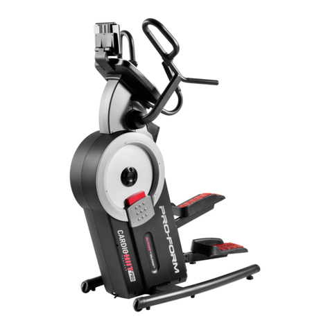
Pro-Form Air Walker PFMC77755 User manual

Pro-Form

Pro-Form Air Walker PFMC77755 User manual

Pro-Form 831.290822 User manual

Pro-Form

Pro-Form 831.290822 User manual

Pro-Form 630 User manual

Pro-Form

Pro-Form 630 User manual

Pro-Form PFEVEL26040 User manual

Pro-Form

Pro-Form PFEVEL26040 User manual

Pro-Form 850 Ci User manual

Pro-Form

Pro-Form 850 Ci User manual

Pro-Form PFIVEL63012.0 User manual

Pro-Form

Pro-Form PFIVEL63012.0 User manual

Pro-Form 325 CSX User manual

Pro-Form

Pro-Form 325 CSX User manual

Pro-Form PFEL51016.0 User manual

Pro-Form

Pro-Form PFEL51016.0 User manual

Pro-Form G720 User manual

Pro-Form

Pro-Form G720 User manual

Pro-Form PF202010 User manual

Pro-Form

Pro-Form PF202010 User manual

Pro-Form TRAINER 12.0 User manual

Pro-Form

Pro-Form TRAINER 12.0 User manual

Pro-Form AIR WALKER XT User manual

Pro-Form

Pro-Form AIR WALKER XT User manual

Pro-Form PFCCEL39014 User manual

Pro-Form

Pro-Form PFCCEL39014 User manual

Pro-Form Sport XT Olympic User manual

Pro-Form

Pro-Form Sport XT Olympic User manual

Pro-Form SPORT 5.5 User manual

Pro-Form

Pro-Form SPORT 5.5 User manual

Pro-Form AirWalker User manual

Pro-Form

Pro-Form AirWalker User manual

Pro-Form 700 Cardio CrossTrainer User manual

Pro-Form

Pro-Form 700 Cardio CrossTrainer User manual

Pro-Form Hot cross buns User manual

Pro-Form

Pro-Form Hot cross buns User manual

Pro-Form PFEVEL49716.1 User manual

Pro-Form

Pro-Form PFEVEL49716.1 User manual

Pro-Form PFMC12330 User manual

Pro-Form

Pro-Form PFMC12330 User manual

Pro-Form 750 User manual

Pro-Form

Pro-Form 750 User manual

Pro-Form SR 20 User manual

Pro-Form

Pro-Form SR 20 User manual

Pro-Form HYBRID TRAINER User manual

Pro-Form

Pro-Form HYBRID TRAINER User manual

Pro-Form PETL50071 User manual

Pro-Form

Pro-Form PETL50071 User manual

Popular Fitness Equipment manuals by other brands

Revitive Arthritis-Knee user manual

Revitive

Revitive Arthritis-Knee user manual

Domyos BM100 operating instructions

Domyos

Domyos BM100 operating instructions

Movement EDGE PUXADA ALTA Assembly manual

Movement

Movement EDGE PUXADA ALTA Assembly manual

Lifeline LLUWB-BLK owner's manual

Lifeline

Lifeline LLUWB-BLK owner's manual

Precor CW-816 Assembly guide

Precor

Precor CW-816 Assembly guide

Balanced Body Precision Rotator Discs manual

Balanced Body

Balanced Body Precision Rotator Discs manual

G-FITNESS AIR ROWER user manual

G-FITNESS

G-FITNESS AIR ROWER user manual

CAPITAL SPORTS Dominate Edition 10028796 manual

CAPITAL SPORTS

CAPITAL SPORTS Dominate Edition 10028796 manual

Martin System TT4FK user guide

Martin System

Martin System TT4FK user guide

CIRCLE FITNESS E7 owner's manual

CIRCLE FITNESS

CIRCLE FITNESS E7 owner's manual

G-FITNESS TZ-6017 user manual

G-FITNESS

G-FITNESS TZ-6017 user manual

Accelerated Care Plus OMNISTIM FX2 CYCLE/WALK user manual

Accelerated Care Plus

Accelerated Care Plus OMNISTIM FX2 CYCLE/WALK user manual

pedalo 20230165 manual

pedalo

pedalo 20230165 manual

Saebo SaeboStim Pro Instructions for use

Saebo

Saebo SaeboStim Pro Instructions for use

Performance HyperVibe User instructions

Performance

Performance HyperVibe User instructions

Scalamobil S27 Operator's manual

Scalamobil

Scalamobil S27 Operator's manual

Precor Experience Series Service manual

Precor

Precor Experience Series Service manual

FYTTER RedMIUM BENCH BE-T6R manual

FYTTER

FYTTER RedMIUM BENCH BE-T6R manual

manuals.online logo
manuals.online logoBrands
  • About & Mission
  • Contact us
  • Privacy Policy
  • Terms and Conditions

Copyright 2025 Manuals.Online. All Rights Reserved.

CAUTION
Read all precautions and instruc-
tions in this manual before using
this equipment. Keep this manu-
al for future reference.
USERʼS ANUAL
• Assembly
• Operation
• Troubleshooting
• Part List and Drawing
odel No. 831.14787.0
Serial No.
Write the serial number in the
space above for reference.
Serial
Number
Decal
Sears, Roebuck and Co., Hoffman Estates, IL 60179
TABLE OF CONTENTS
WARNINGDECALPLACE ENT ..............................................................2
I PORTANTPRECAUTIONS ................................................................3
BEFOREYOUBEGIN ......................................................................5
PARTIDENTIFICATIONCHART ..............................................................6
ASSE BLY ...............................................................................7
HOWTOUSETHEVIBRATIONPLATFOR ...................................................13
TROUBLESHOOTING .....................................................................17
PARTLIST ..............................................................................18
EXPLODEDDRAWING ....................................................................19
ORDERINGREPLACE ENTPARTS ..................................................BackCover
90DAYFULLWARRANTY ..........................................................BackCover
2
WARNING DECAL PLACE ENT
The warning decals shown here have been applied in
the locations shown. If a decal is missing or illegible,
call 1-888-533-1333 and request a free replacement
decal. Apply the decal in the location shown. Note:
The decals may not be shown at actual size.
3
WARNING: To reduce the risk of serious injury, read all important precautions and
instructions in this manual and all warnings on the vibration platform before using the vibration
platform. Sears assumes no responsibility for personal injury or property damage sustained by or
through the use of this product.
I PORTANT PRECAUTIONS
1. Before beginning any exercise program,
consult your physician. This is especially
important for persons over the age of 35 or
persons with pre-existing health problems.
2. It is the responsibility of the owner to ensure
that all users of the vibration platform are
adequately informed of all precautions.
3. The vibration platform is intended for home
use only. Do not use the vibration platform
in a commercial, rental, or institutional set-
ting.
4. Keep the vibration platform indoors, away
from moisture and dust. Place the vibration
platform on a level surface, with a mat
beneath it to protect the floor or carpet. Do
not place the vibration platform in a garage
or covered patio, or near water.
5. Inspect and properly tighten all parts regu-
larly. Replace any worn parts immediately.
6. Keep children under age 12 and pets away
from the vibration platform at all times.
7. The vibration platform should not be used
by persons weighing more than 300 lbs.
(136 kg).
8. Never allow more than one person on the
vibration platform at a time.
9. Keep your back straight while using the
vibration platform; do not arch your back.
When standing on the vibration platform,
bend your knees slightly and balance your
weight on the balls of your feet.
10. It is recommended that you use the vibration
platform no more than 15 minutes per day
and no more than 3 times per week.
11. Be careful when stepping down from the
vibration platform; your muscles will feel dif-
ferent after you exercise on the vibration
platform.
12. The following is a list of factors and condi-
tions that may make exercising on the vibra-
tion platform inadvisable (this list is not
exhaustive; it is intended only for reference).
If one or more factors or conditions apply to
you, consult your physician before using the
vibration platform.
• Knee or hip implant
• Pacemaker
• Recently placed screws, pins, bolts, or
spirals
• Acute hernia, discopathy, or spondylitis
• Serious heart or vascular disease
• Acute thrombosis
• Tumor
• Serious migraine
• Epilepsy
• Serious diabetes
• Recent wound due to operation
• Fresh inflammation
• Pregnancy
13. If you feel pain or dizziness while exercising,
stop immediately and cool down.
14. ake sure that the dumbbells are secure in
the weight rests when they are not in use.
15. Always remove the dumbbells from the
vibration platform before moving the vibra-
tion platform.
4
16. Use the vibration platform and the included
dumbbells only as described in this manual.
17. When connecting the power cord (see page
14), plug the power cord into a surge suppres-
sor (not included) and plug the surge sup-
pressor into a grounded outlet capable of car-
rying 15 or more amps. No other appliance
should be on the same circuit as the vibration
platform. Do not use an extension cord.
18. Use only a single-outlet surge suppressor
that meets all of the specifications described
on page 14. To purchase a surge suppressor,
see your local Sears store or call the tele-
phone number on the back cover of this
manual and order part number 146148, or
see your local electronics store.
19. Keep the power cord away from heated sur-
faces.
20. Never leave the vibration platform unattend-
ed while it is running. Always unplug the
power cord and switch the reset/off circuit
breaker to the off position when the vibra-
tion platform is not in use. (See the drawing
on page 5 for the location of the circuit
breaker.)
21. DANGER: Always unplug the power
cord when the vibration platform is not in
use and before cleaning the vibration plat-
form. Servicing other than the procedures in
this manual should be performed by an
authorized service representative only.
5
BEFORE YOU BEGIN
Thank you for selecting the revolutionary PROFOR ®
ACTIVATOR V7 vibration platform. The ACTIVATOR
V7 vibration platform offers whole body vibration
options designed to make your workouts effective and
enjoyable.
For your benefit, read this manual carefully before
you use the vibration platform. If you have ques-
tions after reading this manual, please see the back
cover of this manual. To help us assist you, note the
product model number and serial number before con-
tacting us. The model number and the location of the
serial number decal are shown on the front cover of
this manual.
Before reading further, please familiarize yourself with
the parts that are labeled in the drawing below.
Dumbbell
Handlebar
Base
Stop Button
Start Button
Wheel
Power Cord
Reset/Off Circuit Breaker
Dumbbell
Weight Rest
Console
PART IDENTIFICATION CHART
M10 Split
Washer (38)
M10 Nylon
Locknut (32)
M4 x 19mm
Screw (45)
M10 x 35mm Screw (34)
M10 x 20mm
Patch Screw (28)
M10 x 62mm Patch Screw (37)
M10 x 114mm Bolt (33)
M5 x 38mm Screw (40)
M10 x 55mm Patch Screw (20)
M10 x 50mm Patch Screw (51)
M4 x 16mm
Patch Screw (26)
M10 x 68mm Bolt (55)
6
See the drawings below to identify small parts used in assembly. The number in parentheses by each drawing is
the key number of the part, from the PART LIST near the end of this manual. Note: Some small parts may
have been preattached. If a part is not in the hardware kit, check to see if it has been preattached. If a
part is missing, call 1-888-533-1333.
7
1. Attach a Rubber Spacer (29) and a Foot (13) to
the Lower Upright (1) with an 10 x 35mm
Screw (34).
Next, locate the Wire Harness (43) inside the
Lower Upright (1). Connect the Wire Harness to
the base wire as shown. Then, pull the Wire
Harness out of the top of the Lower Upright.
43
1
1
34
13
29
Base
Wire
43
Before beginning assembly, carefully read the
following information and instructions:
• Assembly requires two persons.
• Place all parts in a cleared area and remove the
packing materials. Do not dispose of the packing
materials until assembly is completed.
• For help identifying small parts, see the PART
IDENTIFICATION CHART on page 6.
• Tighten all parts as you assemble them, unless
instructed to do otherwise.
• Assembly may require the following tools (not
included):
one adjustable wrench
one rubber mallet
one Phillips screwdriver
Assembly will be more convenient if you have a
socket set, a set of open-end or closed-end
wrenches, or a set of ratchet wrenches.
ake Assembly Easier
This manual is designed to ensure that the
vibration platform can be assembled successful-
ly by almost anyone. ost people find that if
they set aside plenty of time, assembly goes
smoothly.
ASSE BLY
8
2. Tip: Be careful not to pinch the wires during
this step.
With the help of a second person, carefully tip
the Base (5) onto its side.
Attach the Lower Upright (1) to the Base (5)
with two 10 x 55mm Patch Screws (20), two
10 Split Washers (38), two 10 x 68mm Bolts
(55), and two 10 Nylon Locknuts (32).
2
3. Tip: Orient the Wheel Bracket (35) so that
the arrow sticker is pointing upward.
Attach the Wheel Bracket (35) to the Lower
Upright (1) with two 10 x 20mm Patch Screws
(28).
3
1
5
128
35
20 38
4. Attach the Wheel (30) to the Wheel Bracket (35)
with an 10 x 114mm Bolt (33) and an 10
Nylon Locknut (32). Do not overtighten the
Nylon Locknut; the Wheel must rotate freely.
Note: If the Wheel (30) rattles when the
vibration platform is in use, tighten the 10
Nylon Locknut (32) until the rattling stops.
4
30
33
35
32
32
55
5. Attach the Weight Rest (42) to the Weight Rest
Frame (41) with eight 5 x 38mm Screws (40).
Do not tighten the Screws yet.
5
40 40
40
40
41
42
6. Locate the wire tie inside the Upper Upright (36).
Insert the wire tie through the hole in the Weight
Rest Frame (41).
Next, attach the Upper Upright (36) to the
Weight Rest Frame (41) with two 10 x 50mm
Patch Screws (51) and two 10 Split Washers
(38).
6
36
38
51
Hole
Wire Tie
41
9
7
43
Wire Tie
36
1
43
7. Have a second person hold the Upper Upright
(36) near the Lower Upright (1).
See the inset drawing. Tie the lower end of the
wire tie to the Wire Harness (43) as shown.
Then, pull the upper end of the wire tie until the
Wire Harness is routed through the Upper
Upright (36).
8. Tip: Be careful not to pinch the wires during
this step.
Attach the Upper Upright (36) to the Lower
Upright (1) with four 10 x 20mm Patch Screws
(28) and four 10 Split Washers (38).
See step 5. Tighten the eight 5 x 38mm
Screws (40).
8
28
1
28
38
38
36
10
9. Tip: Orient the Handlebar (39) so that the
sticker with an “R” is in the location shown.
Attach the Handlebar (39) to the Upper Upright
(36) with two 10 x 62mm Patch Screws (37)
and two 10 Split Washers (38).
9
37
38
39
“R”
36
10. Remove the four 4 x 12mm Self-tapping
Screws (27) from the back of the Console (3).
Set the Self-tapping Screws aside until step
13.
10
27
27
3