Promac 212 User manual

CE-Conformity Declaration
CE-Konformitätserklärung
Déclaration de Conformité CE
Product / Produkt / Produit:
Drill Press / Säulenbohrmaschine / Perceuse à Colonne
212 / 212Z
Brand / Marke / Marque:
PROMAC
Manufacturer / Hersteller / Fabricant:
TOOL FRANCE SARL, 9 Rue des Pyrénées, 91090 LISSES, France
We hereby declare that this product complies with the regulations
Wir erklären hiermit, dass dieses Produkt der folgenden Richtlinie entspricht
Par la présente, nous déclarons que ce produit correspond aux directives suivantes
2006/42/EC
Machinery Directive / Maschinenrichtlinie / Directive Machines
2014/30/EU
electromagnetic compatibility
elektromagnetische Verträglichkeit
compatibilité électromagnétique
designed in consideration of the standards
und entsprechend folgender zusätzlicher Normen entwickelt wurde
et été développé dans le respect des normes complémentaires suivantes
EN ISO 12100:2010, EN12717:2001+A1:2009, EN 60204-1:2006+A1:2009,
EN 61000-6-2:2005, EN 61000-6-4:2007+A1:2011
Responsible for the Documentation / Dokumentations-Verantwortung / Résponsabilité de Documentation:
Head Product-Mgmt. / Leiter Produkt-Mgmt. / Resp. Gestion des Produits
TOOL FRANCE SARL
2018-03-02 Christophe SAINT SULPICE, General Manager
TOOL FRANCE SARL, 9 Rue des Pyrénées, 91090 LISSES, France
2

SAFETY INSTRUCTIONS 212 / 212Z
Warning: Failure to follow this warning can result in death or serious injury to yourself or to
third persons.
As with all machines, there are typical dangers associated with the operation and handling of this machine.
Careful operation and correct handling of the machine significantly reduce the risk of accidents. If the normal
precautionary measures are disregarded, risks of accident for the operator are unavoidable.
The machine was designed only for the given types of use. Do not carry out changes of the machine and do not
force it to do a task for which it has not been designed.
If you have any questions about the use of this machine and if you do not find the appropriate answer in this
Instructions Manual, please contact your dealer who will be able to help you.
GENERAL SAFETY RULES FOR THE CORRECT USE OF MACHINES
1.
For your own safety, first read and become familiar with the entire Instructions Manual before operating
the machine. Learn the machine’s applications, its operating limits and specific hazards.
2.
Keep guards in place and in perfect working order, do not remove them.
3.
Always connect the electrical machinery equipped with mains plug with protective contact to a socket
with earth contact.
4.
When using adapters without earth contact, connect directly to the earth terminal of the machine. Never
start a machine that is not connected to an outlet with ground connection.
5.
Always remove loose clamping levers or keys from the machine. Before turning the machine ON,
systematically check that any loose parts have been removed.
6.
Always keep the work area clean. Cluttered work stations and benches invite accidents.
7.
Do not operate the machine in a dangerous environment. Do not use the machine in wet or damp areas
and do not expose it to rain. Always keep the work area and workstation well lit.
8.
Keep children and visitors at a safe distance from the machine and from the work area.
9.
Secure the workshop or workroom against unauthorised access. Fit child safety devices, e.g. lockable
latches, lockable main switches, etc.
10.
Do not overload the machine. Its performance will be better and the operation safer if it is operated
within the specified ranges without exceeding the capacities for which it has been designed.
11.
Do not use tools to carry out a task for which they are not designed.
12.
Wear appropriate clothing: do not wearloose clothing, gloves, neckties, rings, necklaces or bracelets and
other jewellery that may be caught in moving parts of the machine. Wear non-slip footwear. Wear
protective hair covering to contain long hair.
13.
Always wear safety glasses. Proceed according to the accident prevention regulations. Wear also a
dust mask is the drilling operation is dusty.
14.
Secure the workpieces. Always use a vice or a clamping device to hold the workpiece. This is safer than
using your hand and both hands are free to operate the machine.
3

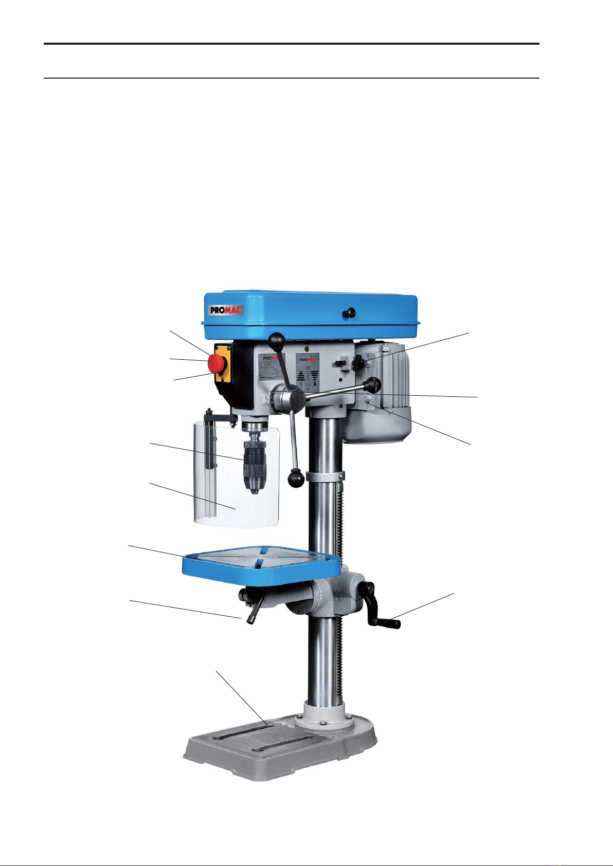
GENERAL SAFETY RULES 212 / 212Z
15.
Do not overreach. Keep proper footing and balance at all times.
16.
Always keep the machine in good working order. To do this, keep the cutting faces sharp and clean for
optimum performance. Follow the operating instructions for cleaning, lubricating and changing accessory
equipment.
17.
Always disconnect the machine from the mains before carrying out any maintenance work or changing
machine parts such as saw blade, cutting tools, etc.
18.
Only use the recommended accessories. Follow the instructions in the User Manual. The use of
unsuitable accessories may cause accidents.
19.
Prevent any accidental starting. Before connecting the equipment to the mains, always check that the operating
switch is in OFF position (“0”).
20.
Never stand on the machine. Serious injuries may occur if the machine tips over or comes in contact with
the cutting tool.
21.
Check for damaged parts. Damaged guards or other parts should be properly repaired or replaced
before further operation.
22.
Never leave a running machine unattended. Always switch off the mains supply. Do not leave the machine
unattended until it has come to a complete standstill.
23.
Never operate the machine if you are under the influence of alcohol, medication or drugs.
24.
Make sure that the machine is disconnected from the mains supply before carrying out works on the electrical
system, drive motor, etc.
NOTES ON SAFETY AT WORK
Transporting the machine
1. The machine weighs up to 50kg.
2. Use suitable means of transport.
3. The machine head is very heavy, there is thus a risk of tipping over during transport!
Work station
1. The work area must be well-lit and well-ventilated.
2. Lighting must be 300 LUXto work safely.
Noise level
According to Point 1.7.4.2u of the Machinery Directive 2006/42/EC
4 measurements were made when the machine was running in no-load mode:
- The microphone was placed on the operator’s head at a medium height.
- The continuous noise level was below 70 dB (A).
- The maximum noise level C was always measured below 130 dB.
Wear always safety googles!
NOTE: during machine operation, the noise intensity varies depending on the type of materials being
processed. The operator must therefore assess the intensity and equip machine users with suitable hearing
protection equipment.
Electrical mains connection
1. The machines model 212 and 212Z are supplied with a mains cable with plug, 230V,50Hz.
Connections as well as changes of the mains connection must be carried out by a qualified technician, in accordance with
standard EN60204-1, Point 5.3.
2. The fuse protection must be at least 10.3A.
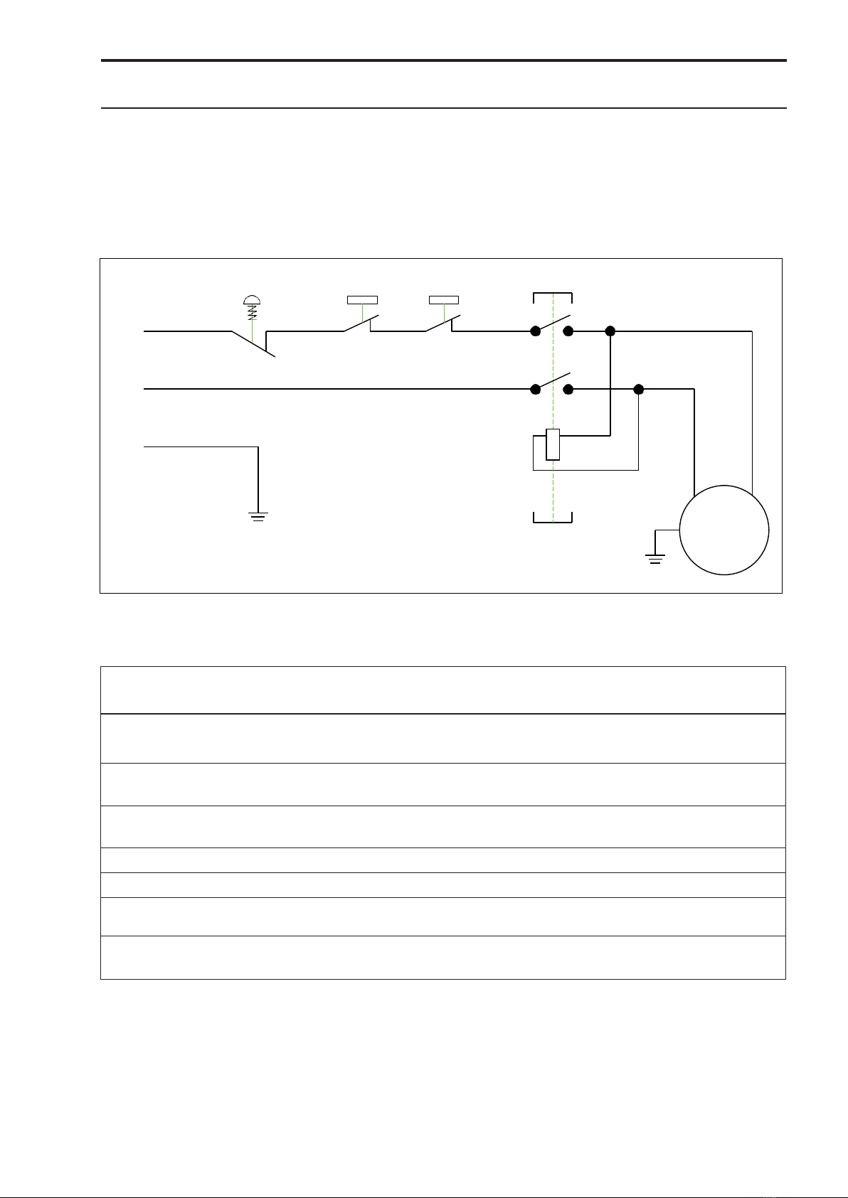
3. The exact electrical data can be found on the identification plate of the machine and in the wiring diagram,
enclosed with this Manual.
4. CAUTION: For all maintenance or conversion works as well as repairs, the machine must be disconnected
from the electrical mains (unplug the machine).
5. The yellow/green ground cable is important for electrical safety. Therefore, proceed with care to install it
correctly. 4

Electrical system
ELECTRICAL SYSTEM
212 / 212Z
The wiring diagram, 230Volt, which can also be found in the motor cover, contains all necessary information
for the correct connection of your machine to the mains. If the mains connection (plug) has to be changed,
this task must be carried out by a qualified technician.
WIRING DIAGRAM
Electrical components –Parts List
Symbol
Function
Technical Data
Parts
Remarks
L1, L2
Power plug
Power cable
250V, 10-16A
H05VV-F 1.5mm2
1
K1 / SB1
“Start” Switch
AC 230V / 10A
1
KEDU, KJD-12
IEC60947-4-1
K1 / SB2
“Stop” Switch
AC 230V / 10A
1
KEDU, KJD-12
IEC60947-4-1
M
Motor
DC 230V / 0.37Kw
1
PE
Electrical grounding
SB3
Microswitch Cover /
AC 230V / 6A
1
SHINOZAKI, AZD-S11
Emergency switch
EN 60947-5-1
SB4
Chip guard switch
AC 230V / 6A
1
Model 212Z only (France)
7
MOTOR
AC 2308A
K1
PE
4
K1
3
230V/50HZ/1PH
L2
2
1
L1
SB1 SB2
SB5
SB4
SB3

TECHNICAL DATA 212 / 212Z
212 / 212Z
Drilling capacity 16mm
Attachment MT 2
Throat depth 168mm
Spindle stroke 80mm
Speeds & speed range 5 speeds, 490-2510 min-1
Distance spindle nose-table 445mm
Distance spindle nose-base 640mm
Spindle diameter 40mm
Column diameter 73mm
Table dimensions 265 x 265mm
Motor 0.37 kW
Overall dimensions 970x320x560mm
Weight 45kg
NOTE: Model 212Z is only available for France
MACHINE DESCRIPTION
PROMAC drilling machines provide universal machining centres that can be used to perform a wide variety
of machining tasks that would otherwise require several machines. The proper use and maintenance of your
machine will guarantee safe function and high working accuracy for many years.
The machine should only be operated by trained users having entirely read and understood these operating
instructions.
For this purpose and before being used, each function of the machine must be tested in “no-load” operation.
FEATURES
1.
The design of this machine enables drilling with a wide range of tools. The machine is equipped with
stepped pulleys for changing the spindle speeds.
2.
The machine is precisely manufactured and can be used without limits by experienced operators due to
its simple handling.
3.
Direct spindle stroke movement for the drilling process.
4.
The large dimensioned column gives the machine great rigidity against distortion, and ensures high
working accuracy.
5.
The machine head, made of grey cast iron, provides the accuracy required.
8
9

ASSEMBLY
Unpacking the machine
212 / 212Z
Unpack the machine with all its parts, and check the parts according to the list below.
1. 13mm Drill chuck with key
2. Adapter MT2/B18
3. Handle with rod (3)
4. Crank
5. Clamping lever
6. Clamping lever
7. Turning handle
8. Screw with spring lock washer (3)
9. Allen wrench
Assemble the machine as shown in the adjacent
figure.
1. Place the column on the base (1) and secure it with
the screws and washers(1).
2. Position the column flange (2) with the rack inserted (3) onto the
column. Fit the crank (4) and fasten using the screw.
Please follow the Note below!
3. Fit the ring (5) and secure it with the screws.
4. Fit the worktable (6) onto the flange (2).
5. Screw in the clamping levers (7).
6. Place the head (8) on the column and adjust to
align it with the base. Tighten the screws.
7. Fit the turning handles (9).
8. Fit the chip guard (10).
6
10
9
8
10
5
3
2
7
4
1
Note about Pos. 2:
Once the assembly of the flange is complete, remove
the screw. This screw is only used for assembly
purpose.
Remove
this screw

Main controls 212 / 212Z
1. “Start”switch
2. Emergency stop switch
3. “Stop”switch
4. V-belt tension lever
5. Depth stop
6. Spindle feed handle
7. Crank of the table
8. Drill chuck
9. Chip guard
10. Clamping lever
11. Swivel table
12. Base
5
11
10
12
1
2
3
4
8
6
9
7
12

INSTALLATION OF THE MACHINE
The following minimum conditions are required to choose a suitable room where the
equipment will be installed:
-
Mains voltage and frequency in accordance with motor’s specifications.
-
Ambient temperature from - 10°C to + 50°C.
-
Relative humidity less than 90%.
212 / 212Z
Anchoring the machine
The machine must be placed on a solid concrete floor, at a minimum distance of 800mm between the rear
side of the machine and the wall, and must be anchored in the ground using screws and expansion plugs or
encased tie rods. Attention must be paid when levelling the machine.
Assembling the machine
1.
Clamp the worktable on the column.
2.
Install the machine in a room/place where the ambient temperature is homogeneous. Make sure that the
machine is not exposed to sunlight, otherwise there is a risk of distortion and loss of accuracy.
3.
Before final connection to the mains, check that the motor rotates clockwise.
4.
The Model 212 must be mounted on a stable workbench or on a pedestal base. It is essential that the
workbench used for the installation is free of distortion. It should also be rigid enough to prevent any
oscillation or vibration during operation.
5.
The machine base has two slotted holes for the fixing screws. Before tightening the screws, check that
the clamping table is aligned in the longitudinal and transverse directions in relation to the rotating work
spindle. To do this, insert a dial gauge with 1/1000 reading with the corresponding attachment into the
spindle and align the table accordingly. For alignment, appropriate metal foils of suitable thickness (feeler
gauges) are to be inserted between the mounting level and the machine base.
Cleaning and lubrication of the machine
For transport purposes, all unpainted parts of the machine are coated with an anti-corrosion grease. This
protection must be completely removed before the machine is put into operation. Use petroleum or mineral
oil for this purpose.
Caution: Do not use any kind of paint thinner, otherwise the paint on the machine will be destroyed. Make
sure that rubber or plastic parts are not in contact with solvents or grease.
After cleaning, all unpainted parts should be coated with a light film of oil of medium viscosity (PROMAC
Part no. 100385).
Cooling lubricant
The Model 212 can be equipped with the coolant system PROMAC Part no. 2064. We recommend the
biological cooling lubricant PROMAC Part no. 9179, container 5kg. The minimum dilution of oil in water is 5-
10%.
Preparatory works before commissioning
Check all parts of the machine for perfect condition and function before commissioning. As far as the
relevant safety precautions and the correct operation of the machine are observed, the accuracy of the
machine is ensured for a long time.
13

COMMISSIONING
a)
Lubricate the spindle and column with PROMAC oil Part no. 100385.
b)
Check that the surface of the clamping table is free of dust, chips or oil residues.
212 / 212Z
c)
Check that the machining tool is sharp and properly clamped, and that the workpiece is securely
clamped.
d)
Make sure that the setting of the spindle speed is not too high and that the cutting speed is appropriate
for the task to be done.
e)
Make sure that everything is prepared before starting the work.
NOTE: before initial operation
a)
The V-belt is not tensioned to avoid distortion. Before use, please tension the belt as described page 17.
b)
Before operating the machine for the first time, let it run in for 1/2 hour without load at approx. 1200 rpm.
AFTER OPERATION
a)
Switch off the machine and disconnect it from the mains.
b)
Unclamp the tool.
c)
Clean the machine, oil bare parts, guides and spindles.
d)
Cover the machine with a cloth to protect it from dust and dirt.
ADJUSTMENT AND SETTING OF THE WORKTABLE
Always wear safety googles!
a)
To raise or lower the worktable, loosen the clamping lever so that the table can be raised and lowered
on the column via the rack.
When the desired height is reached, tighten the clamping lever again to avoid vibrations.
b)
The worktable can be rotated 360° after loosening the clamping screw. Once the desired angular
position has been set, tighten the clamping screw again.
ADJUSTMENT FOR DRILLING
a)
Set the drilling depth using the depth stop.
b)
The drilling feed is now carried out by turning the cross handle.
T-SLOTS ON WORKTABLE AND BASE
For safe working, the workpiece must always be firmly clamped on the cross table using a suitable
clamping tool. The T-slots in the worktable have a dimension of 12 mm. A large selection of suitable
clamping tools can be found in the PROMAC metalworking machines catalogue.
14

SPEED SETTING 212 / 212Z
By shifting the V-belt, the desired speed can be set according to the table below.
1.
Switch off the machine and disconnect it from the mains.
2.
Open the V-belt cover.
3.
Loosen the set screw.
4.
Push the motor against the head housing to release the V-belt.
5.
Change the V-belt position on the pulleys.
6.
Tension the V-belt by means of the motor (approx. 1cm sag).
7.
Close the V-belt cover and start the machine.
17
Spindle Motor
A 2510 Upm / rpm
B 1720 Upm / rpm
C 1200 Upm / rpm
D 800 Upm / rpm
E 490 Upm / rpm
A
B
C
D
E
SPINDLE SPEED

MAINTENANCE 212 / 212Z
Below are the main maintenance operations, which can be divided into daily, weekly, monthly and half-yearly
operations. Failure to carry out the scheduled operations will result in premature wear and reduced machine
performance.
Daily maintenance
-
General cleaning of the machine from chips.
-
Cleaning the spindle cone.
-
Tool wear check.
-
Check protective covers for function.
Weekly maintenance
-
General, careful cleaning of the machine from chips.
-
Cleaning and lubrication of the spindle.
-
Sharpening of the tools.
-
Check protective covers for function and possible defects.
Monthly cleaning
-
Retighten all screws.
-
Check protective covers and devices for integrity.
V-belt maintenance
-
The V-belt must run at the correct tension so that the power of the motor is transmitted to the tool optimally. Pull out
the power cable! Open the belt cover. Loosen the tension screw and tighten or loosen the motor until the belt
reaches the correct tension (approx. 10mm sag).
-
To change the V-belt, loosen the tension screw, replace the V-belt and tension it as described above. Close
the belt cover again!
EXTRAORDINARY MAINTENANCE
Extraordinary maintenance must be carried out by qualified personnel. In any case it is recommended to contact
your machine dealer.
The restoration of the protective covers and safety devices is also to be considered as extraordinary maintenance.
EXTENDED MACHINE STANDSTILL
If the drill press is not used for a long time, it is recommended:
-
To pull out the electrical mains plug.
-
To clean the machine carefully and to preserve it sufficiently.
-
If necessary, cover the machine with a tarpaulin.
DISPOSAL
General provisions
The final dismantling and scrapping of the machine must take into account the nature and composition of the
materials to be disposed of. This means in detail:
-
Ferrous materials and cast iron, which however always consists only of metal, which is a secondary raw material,
must be handed over to the ironworks authorised to carry out the melting, subject to the remuneration of the
components contained.
-
The electrical components, including power cables and electronic material that is considered to be assimilable to
urban waste, can be handed over directly to the waste collection service.
-
For used mineral, synthetic or mixed oils, water-soluble oils and greases, which are special waste, you must
contact the Consortium for Used Oils for storage, transport and subsequent disposal.
Note: As the regulations and laws governing disposal are constantly revised and are therefore subject to
change and new regulations, the user is advised to inform himself about the respective regulations for
dismantling machine tools, which may deviate from the above-mentioned standards. In any case, the
information given is to be regarded as general and purely indicative.
18

EXPLODED VIEW - 212
35 55A
52 44
36 37 56A 42
71 53 43
70 51
50 46
48
105 106
41 41A
40A
40
69-2
69-3
69-1
69
57
58
59
60
69-4
61
69-5
102
68
67
100
101
108
66
64
74
107
49
45
31
32
47
33
34
38
39
28 29 27
26
25
23
16 15 17
22 18
94
95
97
97-1
96
98
103
78
104
24
21
73 75
76
77
14
20 19
99-1
99
72
80
92
79
84 90
87
88
82
86
81
85
13
93
6
11
12
9
8
91 89 10 7
5
4
3
2
1
20

EXPLODED VIEW - 212Z
35 55A
Z52
51 44 43
36
37
56A
71
70
57
58
105
106
47
Z46
42
41 41A
40A40
Z53-1
69-1
69-2
69-3
94
95
Z53
69
Z50
69-4
69-5
59
60
103
104
102
101
68
100
67 66
64
74
108
107
49
22
24
Z46-1 45
Z46-2 31
32
33
38
39 34
29
28 27
2265
23
16 15 17
18
21
97
97-1
96
98
99-1
99
61
73
75
78
76
80
79 77 92
11
84 90
88
87
19
20
14
13
93
6
12 9
72 8
91 89 10 7
86
82 81 85
5
4
3
2
1
21

SPARE PARTS LIST 212 / 212Z
1 PM-212001G
2 PM-212002G Base
Flange 52 PM-212052 V-belt guard
3 PM-212003 Washer
4 PM-212004 Screw
5 PM-212005 Column
6 PM-212006 Rack
7-9 PM-212007 Crank (complete)
10 PM-212010 Screw
11 PM-212011 Clamping lever
12 PM-212012 Shaft
13 PM-212013 Screw
14 PM-212014 Clamping ring
15 PM-212015 Scale ring
Z52 PM-212052Z
53 PM-212053
55A PM-210034B
56A PM-210036
57 PM-212057
58 PM-212058
59 PM-212059
PM-212059A
60 PM-212060
61 PM-212061
Microswitch 212Z
Screw
Switch
Screw
Nut
Spindle pulley
Shaft
Drive taper sleeve
#59~61
Circlip
Ball bearing
16 PM-212016 Rivet 64A PM-212064AG Head housing
17 PM-212017 Pin
18 PM-212018 Handle
19 PM-212019 Handle rod
20 PM-212020 Flange
66-67 PM-212066
68 PM-212068
69 PM-212069
Return spring
Nut
Limit Switch Bracket
69-1 PM-212069A Ball
21 PM-212021 Feed shaft
22 PM-212022 Scale
23 PM-212023 Screw
24 PM-212024 Control knob
69-2
69-3
69-4
69-5
PM-212069B
PM-212069C
PM-212069D
PM-212069E
Pin
Screw
Microswitch
Screw
25 PM-212025 Screw
26 PM-212026 Screw
27 200034 Power cable
28 PM-212028 Spring
29 PM-212029 Rod
31 PM-212031 Nut
32 PM-212032 Fan blade
33 PM-212033G Cover
34 PM-212034 Cable clip
70 PM-212070
71 PM-212071
72 PM-212072
73 PM-212073
74 PM-212074
75 PM-212075
76 PM-212076
77 PM-212077
78 PM-212078
79 100188
Screw
Nut
Table
Washer
Ball bearing
Spindle guide
Ball bearing
Retaining ring
Spindle
Adapter
35 Cable 80 PM-212080 Wedge
36 PM-212036 Screw
37 PM-212037 Fastener 81 PM-2121081
82 PM-212082 Washer
Screw
38 PM-212038G Motor support 84 947316CN Quick-release chuck
39 PM-212039 Screw
40 PM-212040G Motor
40A PM 363200 Capacitor
150MFD / 250V
41
PM-212041BG
Junction box
947316 16mm
Quick-release chuck
16mm / 212Z
41A PM-212041C Gasket
42 PM-212042 Screw
43 PM-212043 Motor pulley
44 PM-212044 V-belt
45 PM-212045 Screw
46 PM-212046 Microswitch
47 PM-212047 Screw
48 PM-212048 Switch plate
49 PM-212049 Screw
50 PM-212050 Plate
51 PM-212051 Knob
22
85 PM-212085
86 PM-212086
87 PM-212087
88 PM-212088G
89 PM-212089G
90 PM-212090
91 PM-212091
92 PM-212092
93 PM-212093
94 PM-212094B
95-99 PM-212102
Lever
Screw
Mark
Arm
Flange
Rivet
Scale
Gear
Worm screw
Washer
Guard including
support

SPARE PARTS LIST 212 / 212Z
97-1 PM-212097A
99-1 PM-212097B Washer
Screw
99 PM-212099 Guard
100 PM-2110021 Cover
101 PM-210092B Screw
102 PM-211059B Plate
103 PM-210092B Screw
104 PM-210091B Emergency Stop
105 PM-210084B Fastener
106 PM-210085B Screw
107 PM-210086B Nut
108 PM-210087B Cable grommet
Only for 212Z (France)
Z46-1 PM-212046Z Screw
Z46-2 PM-212046Z-2 Nut
Z50 PM-212050Z Plate
Z53 PM-212053Z Screw
Z52 PM-212052ZR Belt housing
Z53-1 PM-212053Z-1 Nut
Accessories
2021
Quick-clamping vice
9082
Vice 75mm
9083
Vice 100mm
9336
T-slide 12mm

Warranty / Garantie
TOOL FRANCE SARL guarantees that the supplied product(s) is/are free from material defects and manufacturing
faults. This warranty does not cover any defects which are caused, either directly or indirectly, by incorrect use,
carelessness, damage due to accidents, repairs or inadequate maintenance or cleaning as well as normal wear
and tear.
Further details on warranty (e.g. warranty period) can be found in the General Terms and Conditions (GTC) that
are an integral part of the contract.
These GTC may be viewed on the website of your dealer or sent to you upon request.
TOOL FRANCE SARL reserves the right to make changes to the product and accessories at any time.
TOOL FRANCE SARL garantiert, dass das/die von ihr gelieferte/n Produkt/e frei von Material- und
Herstellungsfehlern ist. Diese Garantie deckt keinerlei Mängel, Schäden und Fehler ab, die - direkt oder indirekt -
durch falsche oder nicht sachgemäße Verwendung, Fahrlässigkeit, Unfallschäden, Reparaturen oder unzureichende
Wartungs- oder Reinigungsarbeiten sowie durch natürliche Abnutzung durch den Gebrauch verursacht werden.
Weitere Einzelheiten zur Garantie können den allgemeinen Geschäftsbedingungen (AGB) entnommen werden.
Diese können Ihnen auf Wunsch per Post oder Mail zugesendet werden.
TOOL FRANCE SARL behält sich das Recht vor, jederzeit Änderungen am Produkt und am Zubehör vorzunehmen.
TOOL FRANCE SARL garantit que le/les produit(s)fourni(s) est/sont exempt(s) de défauts matériels et de
défauts de fabrication.
Cette garantie ne couvre pas les défauts, dommages et défaillances causés, directement ou indirectement, par l'utilisation
incorrecte ou inadéquate, la négligence, les dommages accidentels, la réparation, la maintenance ou le nettoyage
incorrects et l'usure normale.
Vous pouvez trouver de plus amples détails sur la garantie dans les conditions générales (CG).
Les CG peuvent être envoyées sur demande par poste ou par e-mail.
TOOL FRANCE SARL se réserve le droit d'effectuer des changements sur le produit et les accessoires à tout moment.
TOOL France SARL
9 Rue des Pyrénées
91090 LISSES France
www.promac.fr
R
This manual suits for next models
1
Table of contents
Other Promac Power Tools manuals

Promac
Promac 378CLB User manual

Promac
Promac 212VLL User manual

Promac
Promac JD-32120 User manual

Promac
Promac 214AB-M User manual

Promac
Promac JD-3285-M User manual

Promac
Promac JDT-4024 User manual

Promac
Promac 378VB User manual

Promac
Promac 930ELB User manual

Promac
Promac PBM-1839V User manual

Promac
Promac BX-840VADT User manual
Popular Power Tools manuals by other brands

AP Diving
AP Diving RBV07 Series Maintenance manual

GYS
GYS 051829 manual

HSS Hire
HSS Hire TE1000 Operating & safety guide

Kyocera
Kyocera TJEP 5702551001479 Safety and operation instructions

ODU
ODU 080.000.062.000.000 instruction manual

Scheppach
Scheppach HMS850 Translation from the original instruction manual