Promac 930VLB User manual

930VLB
Drill Press / Bohrmaschine / Perceuse
Original:
GB
Operating Instructions
DE
Bedienungsanleitung
FR
Instructions de
fonctionnement
Schweiz / Suisse France
JPW (TOOL) AG TOOL France / PROMAC
Tämperlistrasse 5 57, rue du Bois Chaland, Z.I. du Bois Chaland
CH-8117 Fällanden Switzerland case postale 2935 FR-91029 Evry Cedex
www.promac.ch www.promac.fr
M-930VLB-M 2017-07

1
CE‐Conformity Declaration
CE‐Konformitätserklärung
Déclaration de Conformité CE
Product / Produkt / Produit:
Drill Press
Bohrmaschine
Perceuse
930VLB
Brand / Marke / Marque:
PROMAC
Manufacturer / Hersteller / Fabricant:
JPW (Tool) AG, Tämperlistrasse 5, CH‐8117 Fällanden
Schweiz / Suisse / Switzerland
We hereby declare that this product complies with the regulations
Wir erklären hiermit, dass dieses Produkt der folgenden Richtlinie entspricht
Par la présente, nous déclarons que ce produit correspond aux directives suivantes
2006/42/EC
Machinery Directive
Maschinenrichtlinie
Directive Machines
2014/30/EU
electromagnetic compatibility
elektromagnetische Verträglichkeit
compatibilité électromagnétique
designed in consideration of the standards
und entsprechend folgender zusätzlicher Normen entwickelt wurde
et été développé dans le respect des normes complémentaires suivantes
EN ISO 12100:2010
EN 12717:2001+A1:2009
EN 60204‐1:2006+A1:2009
EN 61000‐6‐2:2005
EN 61000‐6‐4:2007+A1:2011
Responsible for the Documentation / Dokumentations‐Verantwortung / Résponsabilité de Documentation:
Hansjörg Meier
Head Product‐Mgmt. / Leiter Produkt‐Mgmt. / Resp. Gestion des Produits
JPW (Tool) AG
2016‐05‐24 Alain Schmid, General Manager
JPW (Tool) AG, Tämperlistrasse 5, CH‐8117 Fällanden
Schweiz / Suisse / Switzerland

2
GB - English
Operating Instruction
Dear Customer,
Many thanks for the confidence you have shown in us with the purchase of your new PROMAC-machine. This
manual has been prepared for the owner and operators of a 930VLB Inverter Variable Speed Drilling Machine
to promote safety during installation, operation and maintenance procedures. Please read and understand the
information contained in these operating instructions and the accompanying documents. To obtain maximum
life and efficiency from your machine, and to use the machine safely, read this manual thoroughly and follow
instructions carefully.
Declaration of conformity
On our own responsibility we hereby declare that this product complies with the regulations* listed on page 1.
Designed in consideration with the standards **.
JPW Group Warranty
JPW (Tool) AG guarantees that the supplied product(s) is/are free from material defects and manufacturing
faults.
This warranty does not cover any defects which are caused, either directly or indirectly, by incorrect use,
carelessness, damage due to accidents, repairs or inadequate maintenance or cleaning as well as normal wear
and tear.
Further details on warranty (e.g. warranty period) can be found in the General Terms and Conditions (GTC)
that are an integral part of the contract.
These GTC may be viewed on the website of your dealer or sent to you upon request.
JPW (Tool) AG reserves the right to make changes to the product and accessories at any time.

3
Table of Contents
Section Page
Table of Contents ................................................................................................................................................ 3
Warnings ............................................................................................................................................................. 4
Machinery General Safety Warnings.................................................................................................................. 4
Safety Instructions for Drill Presses.................................................................................................................... 5
1. General Specifications................................................................................................................................... 6
2. Product Features and Terminology .............................................................................................................. 7
3. Getting to Know Your Machine..................................................................................................................... 8
3.1 Control Panel ...................................................................................................................................... 8
3.2 The Machine Head.............................................................................................................................. 8
3.3 The Work Table................................................................................................................................... 8
3.4 The Coolant Tank and Pump............................................................................................................... 8
4. Transporting the Machine............................................................................................................................. 9
5. Machine Installation ..................................................................................................................................... 9
5.1 Positioning the Machine ..................................................................................................................... 9
5.2 Anchoring the Machine ...................................................................................................................... 9
5.3 Minimum Requirement for Housing the Machine.............................................................................. 9
5.4 Assembling Loose Parts ...................................................................................................................... 9
5.5 Electrical Connection of the Machine................................................................................................. 9
5.6 Coolant................................................................................................................................................ 9
6. Machine Operation ....................................................................................................................................... 10
6.1 Control Panel ...................................................................................................................................... 10
6.2 Depth Indicator................................................................................................................................... 10
6.3 Operation Cycle .................................................................................................................................. 10
7. Machine Adjustment..................................................................................................................................... 11
7.1 Adjusting the table & Rack Height ...................................................................................................... 11
7.2 Radial Head Position Adjustment ....................................................................................................... 12
7.3 Tool Installation and Uninstallation.................................................................................................... 12
7.4 The Spindle Shield............................................................................................................................... 12
8. Operating Precautions .................................................................................................................................. 13
9. Maintenance.................................................................................................................................................. 13
9.1 Replacement of V-Belt........................................................................................................................ 13
9.2 Lubrication and Routine Maintenance ............................................................................................... 14
10. Troubleshooting ............................................................................................................................................ 15
10.1 The inverter ........................................................................................................................................ 15
10.2 General Trouble Shooting................................................................................................................... 17
11. Exploded View & Parts List ........................................................................................................................... 18
11.1 Breakdown for Table/ Base Assembly ................................................................................................ 18
Part List for Table/ Base Assembly ..................................................................................................... 19
11.2 Breakdown for Head Assembly........................................................................................................... 20
Part List for Head Assembly ................................................................................................................ 21
11.3 Breakdown for Electric Box Assembly ................................................................................................ 24
Part List for Electric Box Assembly...................................................................................................... 25
11.4 Wire Diagram...................................................................................................................................... 26

4
Warnings
- Misuse of this machine can cause serious
injury.
- For safety, machine must be set up, used and
serviced properly.
- Read, understand and follow instructions in the
Operating Instructions and Parts Manual which
was shipped with your machine.
When setting up machine:
- Always avoid using machine in damp or poorly
lighted work areas.
- Always be sure the machine support is securely
anchored to the floor or the work bench.
When using machine:
- Always wear safety glasses with side shields
- Never wear loose clothing or jewelry.
- Never overreach—you may slip and fall.
When servicing machine:
- Always disconnect the machine from its
electrical supply while servicing.
- Always follow instructions in Operating
Instructions and Parts Manual when changing
accessory tools or parts.
- Never modify the machine without consulting
PROMAC.
You—the stationary power tool user—hold the
key to safety.
Read and follow these simple rules for best results
and full benefits from your machine. Used
properly, PROMAC machinery is among the best in
design and safety. However, any machine used
improperly can be rendered inefficient and unsafe.
It is absolutely mandatory that those who use our
products be properly trained in how to use them
correctly. They should read and understand the
Operating Instructions and Parts Manual as well as
all labels affixed to the machine. Failure in
following all of these warnings can cause serious
injuries.
Machinery General Safety
Warnings
1. Always wear protective eye wear when
operating machinery. Eye wear shall be
impact resistant, protective safety glasses
with side shields which comply with ANSI
Z87.1 specifications. Use of eye wear which
does not comply with ANSI Z87.1
specifications could result in severe injury
from breakage of eye protection.
2. Wear proper apparel. No loose clothing or
jewelry which can get caught in moving
parts. Rubber soled footwear is
recommended for best footing.
3. Do not overreach. Failure to maintain
proper working position can cause you to
fall into the machine or cause your clothing
to get caught, pulling you into the machine.
4. Keep guards in place and in proper working
order. Do not operate the machine with
guards removed.
5. Avoid dangerous working environments. Do
not use stationary machine tools in wet or
damp locations. Keep work areas clean and
well lit.
6. Avoid accidental starts by being sure the
start switch is "OFF" before plugging in the
machine.
7. Never leave the machine running while
unattended. Machine shall be shut off
whenever it is not in operation.
8. Disconnect electrical power before
servicing. Whenever changing accessories
or general maintenance is done on the
machine, electrical power to the machine
must be disconnected before work is done.
9. Maintain all machine tools with care. Follow
all maintenance instructions for lubricating
and the changing of accessories. No
attempt shall be made to modify or have
makeshift repairs done to the machine. This
not only voids the warranty but also
renders the machine unsafe.
10. Machinery must be anchored to the floor.
11. Secure work. Use clamps or a vise to hold
work, when practical. It is safer than using
your hands and it frees both hands to
operate the machine.
12. Never brush away chips while the machine
is in operation.

5
13. Keep work area clean. Cluttered areas invite
accidents.
14. Remove adjusting keys and wrenches
before turning machine on.
15. Use the right tool. Don't force a tool or
attachment to do a job for which it was not
designed.
16. Use only recommended accessories and
follow manufacturer's instructions
pertaining to them.
17. Keep hands in sight and clear of all moving
parts and cutting surfaces.
18. All visitors should be kept at a safe distance
from the work area. Make workshop
completely safe by using padlocks, master
switches, or by removing starter keys.
19. Know the tool you are using —its
application, limitations, and potential
hazards.
Familiarize yourself with the following safety
notices used in this manual:
This means that if precautions
are not heeded, it may result in minor injury
and/or possible machine damage.
This means that if precautions
are not heeded, it may result in serious or even
fatal injury.
Safety Instructions for Drill
Presses
1. All work shall be secured using either
clamps or a vise to the drill press table. It is
unsafe to use your hands to hold any
workpiece being drilled.
2. Drill press head and table shall be securely
locked to the column before operating the
drill press. This must always be checked
prior to starting the machine.
3. Always use the correct tooling. Tooling shall
always be maintained and properly
sharpened. All tooling must be run at the
proper speeds and feeds as they apply to
the job. Use only recommended accessories
and follow those manufacturer's
instructions pertaining to them. Tooling
shall not be forced in to any work piece but
fed according to the proper specifications.
Failure to follow these instructions will not
only ruin the tooling as well as the machine,
but can cause serious injury.
4. Never brush away any chips while the
machine is in operation. All clean up should
be done when the machine is stopped.
5. Keep hands in sight. Do not put hands or
fingers around, on, or below any rotating
cutting tools. Leather safety gloves should
be used when handling any sharp objects or
cutting tools. See Figure A.
6. Always wear protective eye wear when
operating, servicing or adjusting machinery.
Eyewear shall be impact resistant,
protective safety glasses with side shields.
Figure B.
7. When drilling in material which causes dust,
a dust mask shall be worn. See Figure C.
8. Avoid contact with coolant, especially
guarding the eyes.
9. Non-slip footwear and safety shoes are
recommended. See Figure D.
10.
Wear ear protectors (plugs or muffs) during
extended periods of operation. See Figure E.
CAUTION
WARNING

6
1. General Specifications
Main power....................................................................................................... 1HP/ 400V / 50Hz / 3PH / 8P
Drilling capacity................................................................................................. Ø 25mm
Tapping capacity ............................................................................................... 13 mm
Swing................................................................................................................. 508 mm
Spindle taper..................................................................................................... MT-3
Spindle travel .................................................................................................... 125 mm
Quill diameter ................................................................................................... 62mm
Column diameter .............................................................................................. 92 mm
Table Size .......................................................................................................... 350 x 350 mm
Table slot........................................................................................................... 13.8 mm
Base size............................................................................................................ 392 x 700 mm
Distance Spindle nose to table (Max.) .............................................................. 635 mm
Distance Spindle nose to base .......................................................................... 1165 mm
Distance Spindle to Column .............................................................................. 254 mm
Spindle speed.................................................................................................... 100 ~ 2800 rpm
Number of Spindle Speeds................................................................................ 2 steps Variable Speed
Net weight......................................................................................................... 180 kg
Machine size ..................................................................................................... 930 x 540 x 2040 mm

7
2. Product Features and Terminology
Pulley Cover
Main Motor
Electric enclosure
Quill feed levers
Column
Riser handle
Pump
Mounting slots
Digital Tachometer
Control Panel
Safety guard
Coolant nozzle
Spindle
Work Table
Vise/ Table lock
Vise
Base & Coolant

8
3.Getting to know your
Machine
This machine is equipped with drilling and
tapping functions. The machine's structure is
rigid and is driven by a well-sized V-belt, which
in turn generates powerful spindle rotation.
Controlled by inverter, it is run with a variable
speed range for easy and safe speed
adjustment. In terms of material, the entire
machine body including the base, table and
column are made by high-strength casting iron
for higher durability.
This manual contains procedures for both
speed control versions. The manual provides
separate instructions when differences in
operation and maintenance exist.
3.1. Control Panel
A. Power ON Switch
B. Power OFF Switch
C. Emergency Stop Switch
D. Reverse Switch
E. RPM Display
F. Spindle Speed Control
G. Coolant Pump Switch
H. Drilling/Tapping Selector
I. Work Lamp Switch
After daily use, disconnect machine from
power source or press emergency stop switch
to shut off the power completely. Do not keep
the machine connected over 24 hours, it may
cause damage to the machine.
3.2. The Machine Head
The machine head is fixed to the column. It
allows more intensity in work piece machinery.
3.3. The Work Table
The work table can be position at varying
heights, and it is T-slotted to allow the use of
M12 T-nuts. Please limit the maximum weight
of the work piece to 60 kg.
Overloading the table may affect the accuracy
of the table.
At the opposite side of work table, there is a
durable vise for flexible use.
By the help of lock nut and tilting scale on the
table bracket, user can freely rotate both work
table and vise along the axle. It allows more
flexibilities in work piece machinery at different
angle.
3.4. The Coolant Tank and Pump
The coolant tank holds coolant, which pumped
to the work piece for cooling and lubricating
while cutting. Coolant is a solution that lowers
tool wear and enhances drilling by cooling and
lubricating the drilling tool.

9
4.Transporting the Machine
The machine will be delivered in a closed crate.
For transport use a forklift or hoist. Make sure
the machine does not tip or fall off during
transport.
Danger of tipping due to high gravity center!
During handling, the machine shall be lifted
only in vertical direction.
Please refer to instruction manual in
specification and machine weight to arrange
handling manner. Be sure to use capable fork -
lifter or hoist to lift of machine. The handling
and transportation shall be carried out by
qualified persons. Fork - lift or hoist can be
used in handling and shall be operated by
qualified driver.
Before handling, make sure all movable parts
are secured in their position and all movable
accessories should be removed from machine.
The steel rope should average pull the machine
head, table and column tightly.
Keep all the processes in a carefully and slightly
condition. Bump or crash are strictly
prohibited. It will cause precision shift and
electronic controller damaged.
5.Machine Installation
5.1. Positioning the Machine
I. The head and the worktable of the machine
can be rotated 360, so choose a location
with enough space and solid foundation.
II. Clean all rust protected surfaces with a mild
solvent e.g. petroleum.
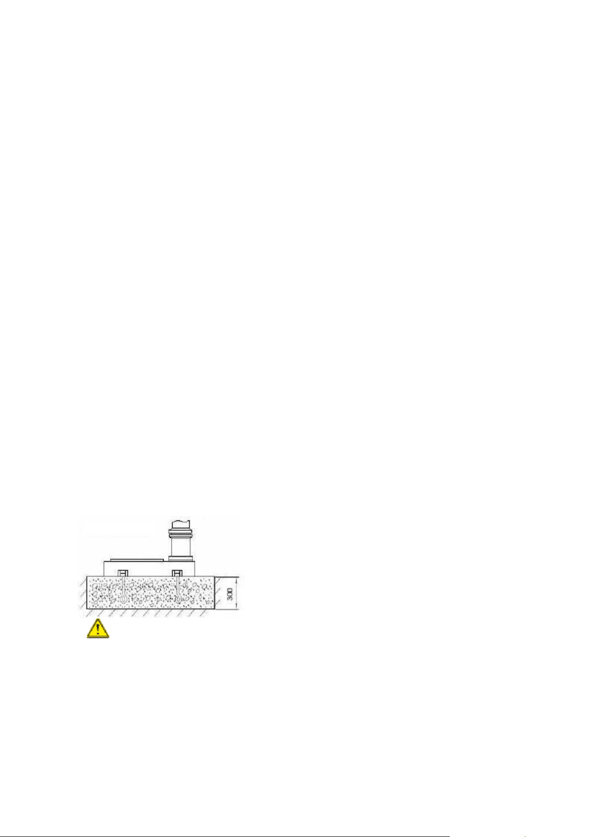
5.2. Anchoring the Machine
Assure the sufficient load capacity and
proper condition of your lifting devices.
I. Position the machine on a firm and level
concrete floor.
II. A minimum distance of 800mm towards a
rear wall must be kept (for access to the
electrical box).
III. Anchor the machine to the ground, as
shown in the diagram, using screws and
expansion plugs or sunken tie rods that
connect through holes in the base.
5.3. Minimum Requirement for
Housing the Machine
Please comply with the following terms to
maximize the life and performance of the
machine and its components.
The Main voltage and frequency complying
with the requirements for the machine's
motor.
Environment temperature from -10°C to
+50°C.
Relative humidity not over 90%.
5.4. Assembling Loose Parts
Attach Riser handle to the necessary
crankshaft, and use Hex-wrench to
tighten/loosen the machine head lock nut.
5.5. Electrical Connection of the
Machine
Make sure whether the voltage 400V
matches the requirement for the machine,
prior to connection to power supply. If the
machine cannot be operated after wires
have been connected, please check the
following items:
I. Is the Emergency switch released?
II. Is the door of the electrical cabinet is
properly closed and switched ON
(locked) position?
III. Is the safety guard in the proper
position (closed)?
5.6. Coolant
Before operating a new machine, please
add coolant to the coolant tank, fill the
coolant to at least half (minimum 6 liters).
User can choose the one most suitable for
their requirements. For your reference
SHELL LUTEM OIL ECO is highly
recommended. The ratio of oil and water is
50% respectively. The minimum percentage
of oil diluted in water is 8~10%. Cleaning is
required when iron filings clog the screen
(Fig.4) at the bottom right corner of the
water drain entry at the base.

10
6.Machine Operation
6.1. Control Panel
A. Power ON Switch: Starts the motor.
B. Power OFF Switch: Stops the motor. As the
power still exists, pressing ON restarts the
machine.
C. Emergency Stop Switch: Stops the machine.
Turn the switch clockwise to unlock the
switch before starting the machine.
D. Reverse Switch: Reverses the spindle
rotation. Used for exiting a tapping
operation.
E. RPM Display: Displays the rate of spindle
rotation in RPM.
F. Spindle Speed Control knob: Changes the
rate spindle rotation.
G. Pump Switch: Starts the coolant flow for
cutting.
H. Drilling/Tapping Selector: Selects the mode
of operation
Change speeds only while the machine is
running. Then spindle speed can be adjusted to
the proper cutting RPM by using the spindle
speed handle (F in figure). The spindle speed
ranges is from 100 to 2800 rpm.
6.2. Depth Indicator
A drilling depth indicator is provided on the
side of the drill head. The indicator can be set
for depths up to 12.5 cm. The lock knob is
provided at the side, on the top of quill lever.
Before starting the motor:
I. Set the depth to zero by lowering and
holding the cutting tools to the surface of
the work piece. Use quill lever to lower the
spindle.
II. Unlock the depth scale by turning the lock
knob.
III. Set the depth stop by rotating the depth
stop stud to the desired depth.
IV. Lock the depth scale by turning the lock
knob.
6.3. Operation Cycle
Safety chuck guard must be in position, electric
box must be closed and locked, and unlock
emergency stop switch (C) by turning the red
cap of the switch clockwise to start machine. In
a critical condition, stop machine by hitting
emergency stop switch or Power OFF switch (B)
to stop machine.
1. Check if the head is secured.
Failure to secure the head can result in
damage of the machine and personal injury.
2. Secure the work piece to the table.
3. Use crankshaft to adjust the table to the
desired height.
4. Use lock-lever to secure the table.
5. Use the spindle/quill feed lever to bring the
drill or tapping tip down to the surface of
the work piece and hold.
6. Set the depth indicator/stop to required
depth.

11
7. Back the drill or tapping tip off the work
piece a bit.
8. Select drilling or tapping mode.
9. Press Power ON switch to begin spindle
rotation.
10. Turn ON the coolant pump switch if
necessary.
In Drilling Mode
11. Use the depth handle to bring the tip of the
drill bit to the surface of the work piece
hold.
12. The required depth is set by previous steps
5 and 6.
13. Adjust the spindle speed control knob, and
observe RPM display to specified spindle
speed.
14. Begin drilling by using the quill feed lever.
In Tapping Mode
In general, speeds for tapping require low
speed which is lower than 120 min-1.
15. Use the depth handle to bring the tip of the
tapping bit to the surface of the work piece
and hold.
16. The required depth is set by previous steps
5 and 6.
17. Select the spindle speed.
18. Begin tapping by using the quill feed levers.
19. At the end of a tapping or drilling operation,
press the stop button switch to turn off the
machine.
Note: While tapping, pause spindle down feed
at the bottom of operation to allow the
breaking and reversal of rotation of the
spindle.
In general, use low speeds for tapping. Tapping
at high speed will tap more quickly,
but there is a danger of damage to work piece and
tool. Tapping requires an accurate setting for the
depth stop to allow the machine to switch tapping
direction and the removal of the tapping bit.
7.Machine Adjustment
7.1. Adjusting the table & Rack Height
The table can be raised, lowered, and tilted
with desired angles to accommodate the work
piece.
To raise or lower the table, loosen the lever-
locks behind the table bracket, then use the
hand crank to move the table to the desired
height. Then lock the table in position.
To tilt the table, loosen the lock-lever first to
adjust the table to desired angle, then lock the
table in position.
7.2. Radial Head Position Adjustment
Change the radial position of the drill
head only if the drill press base is secured to
the floor. Swinging the drill head without the
base being secured to the floor will cause the
drill press to become unstable and tip over
resulting in injury and/or damage to the
machine.

12
7.3. Tool installation and Uninstallation
1. Clean the drill chuck, arbor and spindle taper
thoroughly before installation. Any insufficient
cleaning on mating surfaces may cause drill
loosen as operating and unsafe conditions.
2. Place a thin wood plank on the worktable to
protect the surface of the worktable and chuck
drill. Draw back the chuck nose into chuck body
and slightly hit the arbor onto the chuck by
rubber hammer.
3. Slide the assembled drill chuck and arbor into
spindle taper, and slightly hit them by rubber
hammer to fit in.
4. Lower the spindle about 100 mm.
5. Place the drift key into the aperture of the quill
and tap the end of the drift key with a hammer
until the bit or chuck arbor falls down.
7.4. The Spindle Shield
This clear plastic shield should be use whenever
conducting a drilling or tapping operation. Clean
the safety guard periodically to provide a clear
view of the work piece. Adjustments can be done
as follows.
1. Lock the vertical height by adjusting the lever
screw.
2. Use knob to lock the horizontal rotation and
position of the safety chuck guard. Loosen
knob to open the safety chuck guard, when it
opened that the power will be shut off.

13
8.Operating Precautions
The following operating and safety precautions
must be observed in order to avoid harm to the
operator or damage to the drill press.
1. Make sure the power voltage is for the
machine. Before connecting the plug to
socket, it is necessary to check the power
spec. to avoid any damage occurring.
2. If the machine is not used for a long time,
the plug should be disconnected.
3. Never put the power cable near the fire or
water environment, to break or press the
power cable is not allowed.
4. The head assembly must be locked to the
column so the thrust produced by drilling
will not force the head assembly up the
column.
5. The work table must be locked to the
column so it will not be forced down the
column.
6. Before drilling, release the quill lock nut to
permit free travel of the quill.
7. Be sure the belt is tightened to the proper
tension.
8. DO NOT start to drill the work piece until
making certain the work piece is held down
securely.
9. MAKE SURE THE DRIVE MOTOR IS RUNNING
BEFORE turning the speed control hand-
wheel in either direction.
10. Point of operation protection is required for
maximum safety. This remains the
responsibility of the user/purchaser
since conditions differ between jobs.
11. Make sure the drill is secured in the spindle
or chuck before attempting to use the drill
press.
12. Make sure the spindle taper is clean and
free of burrs, scoring, and galling to assure
maximum gripping.
13. Lock the quill in position when using any
side-loaded tool.
9.Maintenance
9.1. Replacement of V-Belt
This machine is designed with 2 step pulleys
and V-belt to provide braking response and
torsion strength. V-belt should be replaced
when the belt is worn or broken.
Make sure to disconnect electrical
power to the drill press to avoid the possibility
of inadvertent operation and exposure to
potentially lethal voltage levels.
1. Open the machine head cover.
2. Loosen lock lever to free the motor.
3. Slide the motor toward the pulley.
4. Lift out or remove the V-belt.
5. Replace the belt.
6. Use tension lever on the motor to slide
motor away to tension the belt.
7. Tension should be loose enough to allow 5-
10mm movement when pushing the belt
from the side.
8. Tighten the lock lever to secure the motor
in place.
9. Install the cover.

14
9.2. Lubrication and Routine
Maintenance
Apply oils to the driving parts of the machine prior
to operation and supply coolant during operation
to ensure stability of cutters and the object being
processed. Please refer to the lubrication as below
for more details about use oil. To extend your
machine life, please make a maintenance schedule
daily, weekly, monthly or semi-annual and annual.
Neglecting the machine maintenance will result in
premature wear and poor performance.
9.2.1. Lubrication
1. Lubricate - Column, Quill. Use
machine tool oil with light film of oil.
2. Grease - Rack on the column so
that the worktable can move up/down
smoothly. Use SAE 20 oil. To clean rack
with kerosene before applying oil.
9.2.2. Daily Maintenance
Make a general cleaning by removing
dust and shavings from the machine.
Check that the shields and emergency
stops are in good working order.
After daily use, disconnect machine
from power source or press
emergency stop switch to shut off the
power completely. Do not keep the
machine connected over 24 hours, it
may cause damage to the machine.
9.2.3. Weekly Maintenance
Clean the machine including the
coolant tank. Change the coolant
water once a week.
9.2.4. Monthly Maintenance
Lubricate machine column, spindle
and rack devices.
Check that all screws on the motor,
the pump and the guard are tight and
secure on the right position.
9.2.5. Annual Maintenance
Change the driving belt using type
OPTI-belt 656x8M.
9.2.6. Oils for Lubricating Coolant
Considering the vast range of products
in the market, the user can choose the
one most suited to their own
requirements, using as reference the
type SHELL LUTEM OIL ECO.
THE MINIMUM PERCENTAGE OF OIL
DILUTED IN WATER IS 8~10%.
9.2.7. Oil Disposal
Oil products must be disposed in a
proper manner following local
regulations.
9.2.8. Special Maintenance
Special maintenance operations must
be carried out by skilled personnel.
However, we advise contacting dealer
and/or importer the term special
maintenance also covers the resetting
of protection and safety equipment
and devices.

15
10. Trouble shooting
10.1. The Inverter
Prior to operating all electronic parts, the following aspects should be taken into consideration first
Note: Only eligible and qualified personnel can make electronic adjustments
1. Disconnect machine from power supply.
2. Electronic parts are extremely sensitive, do not use hands or metal tools to remove or install such parts.
3. As remaining voltage still exists in the capacitor even after the electric current has been cut off, wait
until the light disappears from the lighted display completely before proceeding with any work to
prevent any accidents or hazards from occurring.
4. Pay close attention to the electronic circuit board so that they are free from any defects.
5. Never connect the alternating current directly to the output connector (U/V/W) of the speed adjuster.
The electronic self-diagnosis program can notify you of situations like motor overloading and too low or
too high voltage, etc. When the program detects an error, the machine will stop immediately and such
error will be displayed on the inverter's digital display. Follow the solutions to correct any errors. Close
the electrical cabinet and connect machine to power supply.

16
Table of Error Codes for the Inverter
Code
Error description
Solution
O.C
* The voltage inverter detects the
output current exceeds the normal
value.
* Check if voltage of the motor matches with that of
the voltage inverter.
* Check connection between the voltage inverter &
the motor.
* Check if the motor is overloaded.
O.U
* The voltage inverter of the motor is
detected with a D.C. high voltage
lateral pressure value that exceeds the
acceptable range.
* Check if the circuit input voltage matches with that
of the voltage inverter.
* Frequent on/off and switches between clockwise
and reverse directions result in self-protection
from high D.C. high voltage lateral pressures.
O.H
* The touch pole of the voltage inverter
of the motor indicates overheat.
* Check if the circuit input voltage matches with that
of the voltage inverter.
* Ensure the cooling device be free of any foreign
objects or dirt.
O.L
* The frequency converter detects the
output exceeds 150% of normal
standards for 1 minute.
* Check if the motor is overloaded.
Ex:
1. Cutters and tools are blunt?
2. Spindle diameter, gear, speed and volume of feeds
proper?
o.c.A
o.c.d
d.c.n
* Electric current is too large during
acceleration.
* Electric current is too large during
deceleration.
Electric current is too large during
operation.
* Check if the output connection of the motor
adjuster is insulated improperly.
C.F.F
* Grounding or safety wire mistakes
* Check if grounding is proper.
* Replace safety fuses.
* When the diode shows the same mistake numbers
continuously on the monitor, ask for more
information from the after-sales service center.
C.F 1~3 or
others
Abnormal detection inside the frequency
converter
* Place the machine outside the circuit.
* Restart the machine.
* When the diode shows the same mistake numbers
continuously on the monitor, ask for more
information from the after-sales service center.

17
10.2. General Trouble Shooting
Trouble
Probable Cause
Remedy
Spindle does not turn.
Motor overload protector tripped.
Press motor overload reset button.
Circuit breaker tripped.
Reset circuit breaker.
Branch circuit breaker tripped or fuse
blown.
Reset branch circuit breaker/replace fuse.
Open wire in switch circuit.
Repair open circuit.
Defective switch.
Replace switch.
Broken drive belt.
Replace drive belt.
Spindle noisy.
Damaged spindle bearings.
Replace bearings.
Worn spline.
Replace spline.
Drill stalls.
Worn drive belt.
Check condition of belt. Replace if glazed
or slipping on pulleys.
Excessive feed rate for size of drill and
material being drilled. No cutting fluid or
improper cutting fluid.
Reduce feed pressure or use cutting fluid.
Use correct cutting fluid.
Poorly drilled holes.
Drill dull.
Sharpen drill.
Lack of rigidity in hold-down method.
Check that all T-slot hold-downs are tight
and that table-lock and drill head bolts are
tight.
Speed too fast for material and drill size.
Check spindle speed recommendations.
Reduce speed if necessary.
Feed too fast for material and drill size.
Reduce feed rate.
No or improper cutting fluid or coolant
being used.
Use cutting fluid, or change to proper fluid
or coolant for material being drilled.
Improperly ground drill bit.
Check for proper angles and reliefs.
Regrind to proper geometry.
Motor overheating.
Electrical circuit fault.
Check current draw in circuit. Make sure
current draw is the same as rating on
motor plate.
Oversize drill.
Reduce drill size.
Excessive feed.
Reduce feed rate.
No cutting fluid, or wrong fluid.
Use correct cutting fluid for the material
and drill.
Table cannot be raised.
Lack of lubrication.
Lubricate.
No speed readout.
Speed pickup out of adjustment or failed.
Adjust gap between speed pickup and post
spindle pulley. If there is no readout on the
LED speed indicator after adjusting the
gap, replace the speed pickup.

18
11. Exploded View & Parts List
11.1. Breakdown for Table/ Base Assembly

19
Part List for Table/ Base Assembly
Index No.
Part No.
Description
Size
Qty
1
930ELB-01
Base
1
2
930ELB-03
Oil Seal
3
3
WP10
Washer
M10
3
4
930ELB-02
Hex Cap screw
3
5
930ELB-04
Water Net
1
6
930VLB-06
Pan Head Screw
M5x10
4
7
930ELB-07
fastener
1
8
930ELB-08
Hose .
1
9
WP5
Washer
M5
2
10
930ELB-06
Hex Socket Cap Screw
M5*16
2
11
930ELB-09
Coolant Pump
1
12
930ELB-20
Hex Cap screw
M12*50
1
13
930ELB-19
Spring Washer
¢12
1
14
930ELB-10
Flange
1
15
930ELB-11
Hex Cap Screw
M12*50
4
16
930ELB-12
Spring Washer
M12
4
17
930ELB-16
filter Net
1
18
930ELB-17
Hose
1
19
930ELB-18
Fastener
M10-Ø 20
2
20
930ELB-21
Column
92 mm
1
21
930ELB-22
Rack
1
22
930ELB-23
lock block
2
23
930ELB-24
Hex Cap screw
2
24
930ELB-25
handle
1
25
930ELB-26
Hex Cap screw
M8*20
1
26
930ELB-27
Warm Rod
1
27
930ELB-28
Warm Gear Shaft
1
28
930ELB-29
Warm gear
1
29
930ELB-30
Table bracket
1
30
930VLB-30
lock block
2
31
930ELB-31
Lock Handle
2
32
930ELB-32
Scale
1
33
930ELB-33
Rivet
2
34
930ELB-34
Rivet
4
35
930ELB-35
index plate
1
36
930ELB-36
Vise seat
1
37
930ELB-37
Lock Handle
1
38
930ELB-38
Flat Socket Cap Screw
M8
4
39
930ELB-39
Vise plate
2
40
930ELB-40
plate
1
41
930ELB-41
Hex Socket Cap Screw
M6
2
42
930ELB-42
Hex Socket Cap Screw
M5
2
43
930ELB-45
Vise bracket
1
44
930ELB-46
Handle
1
45
930VLB-45
Hex Cap Screw
M8*20
1
46
930ELB-47
Spring Pin
¢6
1
47
930ELB-48
Vise Lead screw
1
48
930ELB-49
Lead Screw Bracket
1
49
HCS820
Hex Cap Screw
M8*20
1
50
930ELB-50
Gib
1
51
930ELB-51
Washer
1
52
930ELB-52
Hex Cap Screw
M24*255
1
53
930ELB-53
Hex Socket Cap Screw
M8*35
3
54
930ELB-54
Hex Nut
M8
3
55
930ELB-55
lock screw
M8*20
1
56
930ELB-56
handle
M12*45
1
57
930VLB-57
index plate
1
58
930ELB-57
hose joint
1
59
930ELB-58
Table
1
60
930ELB-59
Filter Net
1
61
930ELB-72
Locking Ring
1
62
930ELB-73
Pan Head Screw
M6*10
1
Table of contents
Languages:
Other Promac Power Tools manuals

Promac
Promac JDT-4024 User manual

Promac
Promac 378VLB User manual

Promac
Promac 378CLB User manual

Promac
Promac 213A User manual

Promac
Promac 214AB-M User manual

Promac
Promac BX-840VADT User manual

Promac
Promac 212VLL User manual

Promac
Promac 378VB User manual

Promac
Promac JD-3285-M User manual

Promac
Promac 930ELB User manual