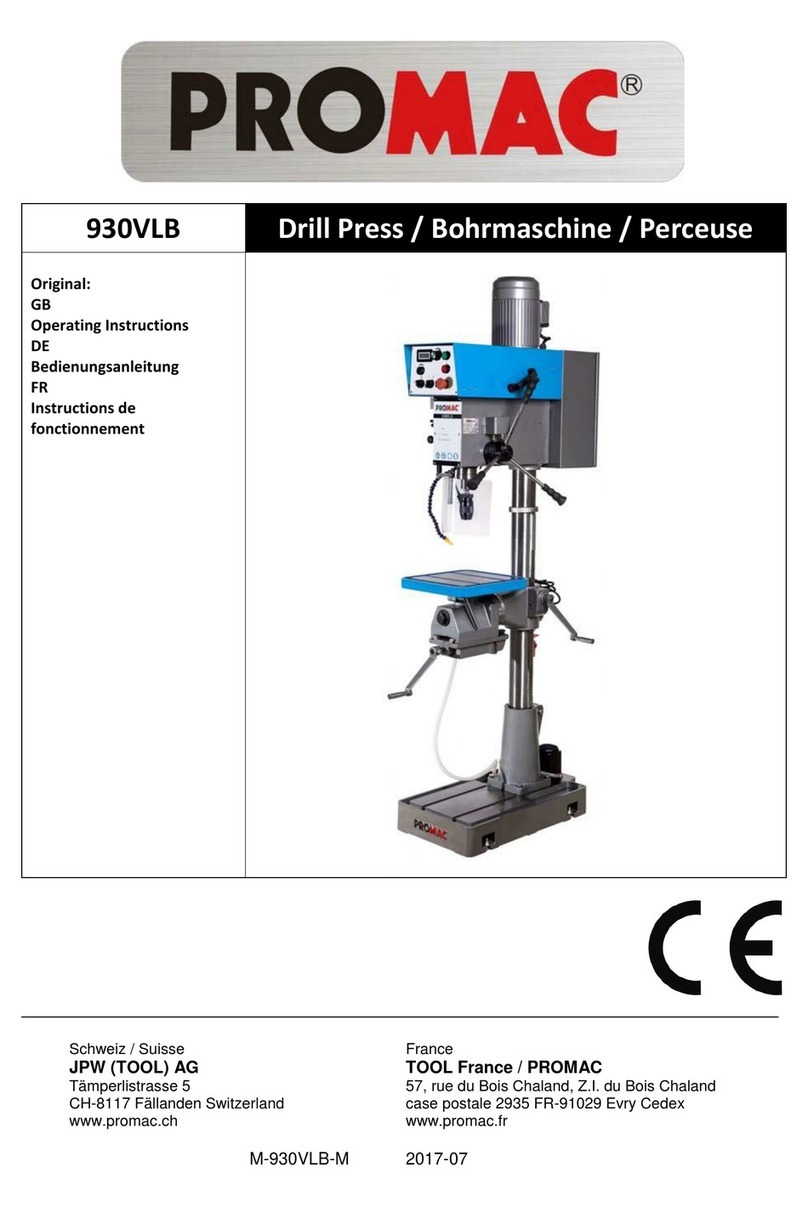
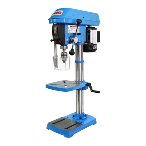
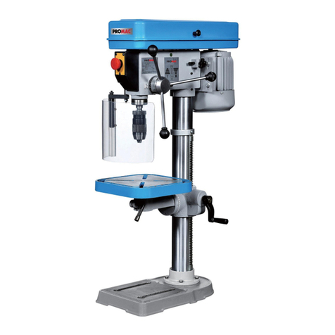
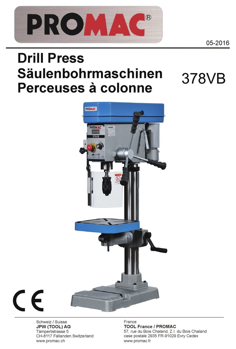
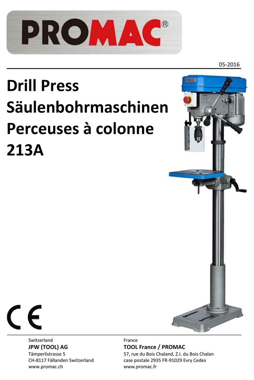
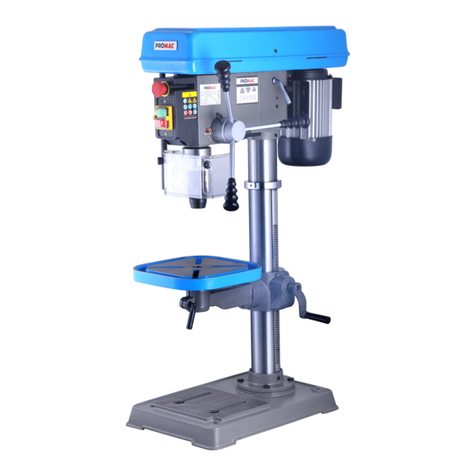
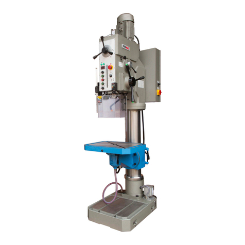
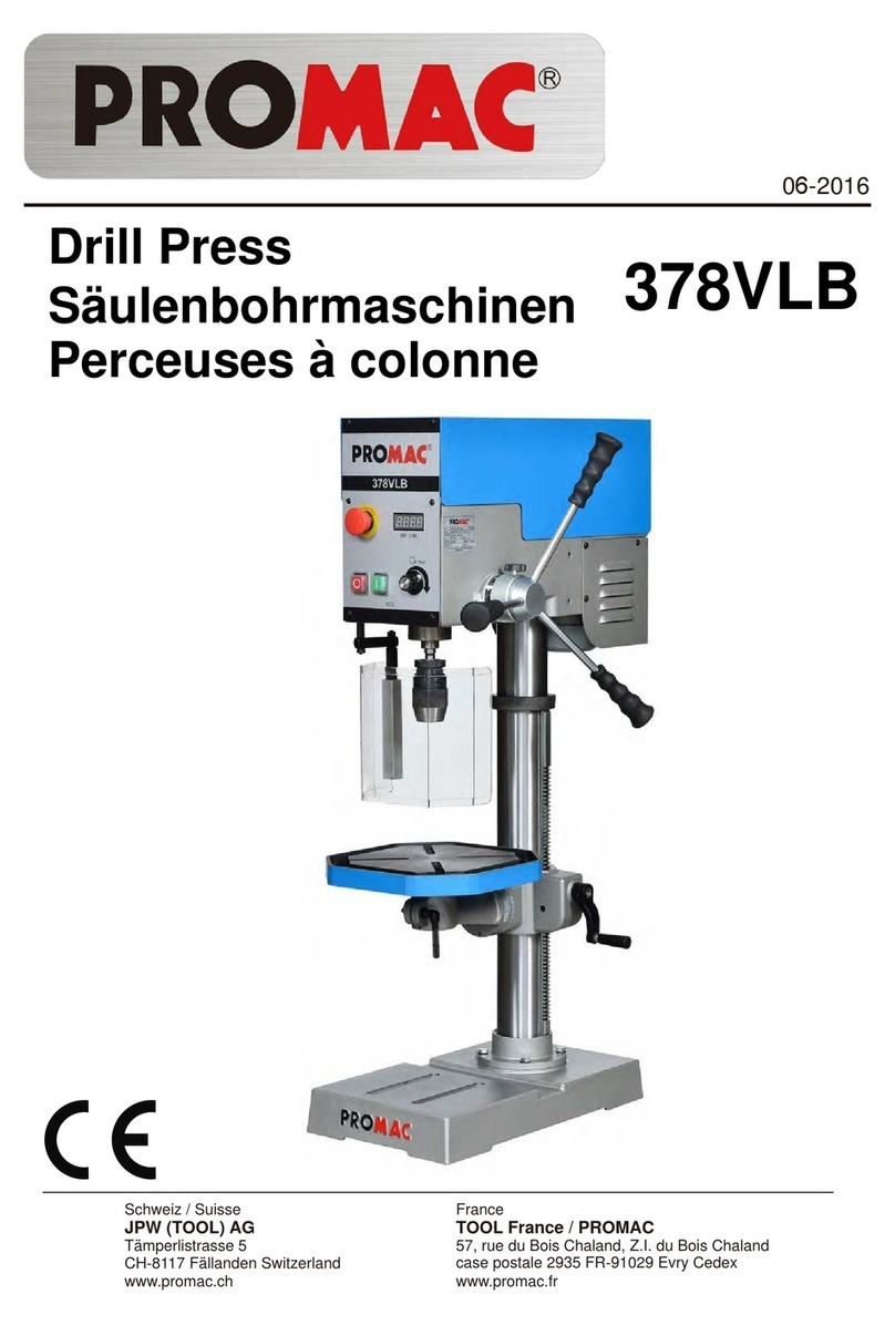
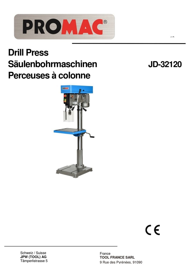
Promac 214AB-M User manual

214AB-M
Drill Press
Säulenbohrmaschinen
Perceuses à colonne
01-2021
TOOL FRANCE SARL
9 Rue des Pyrénées, 91090 LISSES, France
www.promac.fr

CE-Conformity Declara on
CE-Konformitätserklärung
Déclara on de Conformité CE
Product / Produkt / Produit:
Drill Press
Säulenbohrmaschine
Perceuse à colonne
214AB-M
Brand / Marke / Marque:
PROMAC
Manufacturer / Hersteller / Fabricant:
We hereby declare that this product complies with the reg s
Wir erklären hiermit, dass dieses Produkt der folgenden Richtlinie entspricht
Par la présente, nous déclarons que ce produit correspond aux dire es suivantes
2006/42/EC
Machinery Dir e
Maschinenrichtlinie
Dir e Machines
2014/30/EU
electromagne com lity
elektromagne sche Verträglichkeit
lité électromagné que
designed in consider of the standards
und entspechend folgender zusätzlicher Normen entwickelt wurde
et été développé dans le respect des normes complémentaires suivantes
EN ISO 12100:2010
EN 12717:2001+A1:2009
EN 60204-1:2006+A1:2009
EN 61000-6-2:2005
EN 61000-6-4:2007+A1:2011
Responsible for the Documenta on / Dokumenta ons-Verantwortung / Résponsabilité deDocumenta on:
Head Product-Mgmt. / Leiter Produkt-Mgmt. / Resp. Ges on des Produits
TOOL FRANCE SARL
2021-01-07 Christophe SAINT SULPICE, General Manager
TOOL FRANCE SARL
9 Rue des Pyrénées, 91090 LISSES, France
TOOL FRANCE SARL
9 Rue des Pyrénées, 91090 LISSES, France

3
GENERAL SAFETY INSTRUCTIONS
Note: Non-observance of these instructions can result in severe injury.
As with all machinery, there are specific hazards involved with the operation and handling of the machine.
Careful operation of the machine and correct machine handling will effectively lower the risk of possible
accidents. If the usual precautions are disregarded, a risk of accidents for the operator cannot be avoided.
The machine was designed for the specified kinds of use only. We strongly recommend not to operate a
machine that was modified and not to use the machine in a manner it was not designed for.
If you have any questions regarding the operation of this machine and the operating instructions do not give
the required information, please contact your distributor.
GENERAL RULES FOR SAFE HANDLING OF MACHINERY
1. For your own safety, always read the operating instructions before starting the machine. Make yourself
familiar with the machine, its operation and operating restrictions as well as with its specific hazards.
2. Keep safety guards in place and in proper working order.
3. Always connect any electrically operated machines equipped with a grounding-type mains plug to a
grounding-type socket. If adapter plugs without earthing contact are used, a grounding-type connection
on the machine must be carried out by all means. Never operate the machine without grounding-type
connection (earthing).
4. Always remove any loose clamping levers or wrenches from the machine. Make it a habit to check that all
loose operating elements have been removed before turning the machine on.
5. Keep the working area free from obstacles. Working areas and working surfaces blocked by obstacles will
virtually provoke accidents.
6. Do not operate the machine in hazardous working environment. Do not operate power driven machinery
in damp or wet rooms or expose them to rain. Always keep working surfaces and areas well lighted.
7. Keep children and visitors away from the machine. Make sure children and visitors keep a safe distance
from the working area.
8. Safeguard the workshop and the working room against unauthorized access. Attach child-proof locks such
as lockable latches, lockable main switches, etc.
9. Do not overload the machine. Machine performance and machine safety are enhanced when the
machine is operated within the range of performance it was designed for.
10. Do not use any attachments for works they were not designed for.
11. Wear appropriate working clothes; avoid wearing loose clothes, gloves, scarves, rings, necklaces,
bracelets or other jewelry. They might get caught in moving machine components. Wear shoes with anti-
slip soles. Wear a working cap that completely covers long hair.
12. Always wear safety glasses. Observe the accident prevention regulations. Moreover, wear a dust mask for
works with heavy dust contamination.
13. Safely clamp the workpieces. Always use a vise or clamps to hold the workpiece. It is safer than using your
hands and both hands will be free to operate the machine.
4
Always wear safety glasses!
GENERAL SAFETY INSTRUCTIONS
14. Stability must be ensured. Always keep your body in balance and set the feet in a way that ensures
stability.
15. Always keep the machine in good working order. Especially keep the tooling sharp and clean to ensure
best performance. Observe the operg inons for cleaning, lubricng and changing achments.
16. Always disconnect the machine from the mains before performing maintenance work or replacing
machine components such as saw blade, cu tool, etc.
17. Use recommended accessories only. Observe instructions in the operang instrucons. The use of
improper accessories may be hazardous.
18. Avoid accidental start. Prior to the conne of the machine to the mains make sure the power switch is
turned to "0" (OFF).
19. Never climb onto the machine. Severe injury may be caused if the machine s over or if you touch the
cung tool.
20.
Check for any damaged machine components. Before further opere machine, damaged guards or other
parts should be repaired or replaced to ensure they can correctly perform their intende
21. Never leave the machine unaed during Always turn opower supply. Do not leave the
machine un it has come to a complete stop.
22. Never operate the machine under the inence of alcohol or drugs.
23. Before performing any work on the electrical system, on the drive motor, etc, make sure the machine has
been disconnected from power supply.
Information on occupational safety and health
Machine transport
1. The maximum weight of the machine is 164 kg.
2. For machine transport, use appropriate means of transport.
3. The machine is much heavier at its head side so there is pping hazard during
machine transport!
Working environment
1. ent lighng and on of the working room must be ensured.
2. To ensure work can be carried out safely, the must have an illuminance of 300 LUX.
Sound level
1. During oper the sound level of the machine is 70 dB.
2. Depending on the material, the sound level may be even higher when drilling. So wearing appropriate ear
protecon (e.g. ear plugs of mu is required.
Mains connection
1. The machines of the 214AB-M type are supplied including 230V, 50Hz power cord and plug.
Have the mains on and any thereof made by a ed electrician in accordance
with sen 5.3 of the EN60204-1 standard.
2. The fuse used must have a minimum amperage of 10 A.
3. For the detailed electrical data, see the machine's name plate and the wiring diagram ahed to these
instru
4. ATTENTION : Prior to any service or set-up work or repair, disconnect the machine from the mains (pull
out the plug).
5. The yellow/green earth conductor is essenal for the electrical safety. So make sure it is connected
correctly.

5
Electrical system
ELECTRICAL SYSTEM
The wiring diagram (230 Volt ) that is also ed to the lower side of the motor cover contains the
required for the correct connec of the machine to the mains. Any moca of the mains
connon (plug) have to be carried out by a qu electrician.
Wiring Diagram
Parts list of the electrical system (EN)
Index No. Funcon Specicans Qty. Manufacturer Remarks
XP Power plug 250V, 8A 1
Power cord H05VV-F0.75mm
2
1
SB 1 Pustart” AC 230V/10A 1
KEDU KJD-12
IEC 60947-4-1
SB 2 Pushbuon Stop” AC 230V/10A 1
KEDU KJD-12
IEC 60947-4-1
M Motor AC 230V/0.75Kw 1
K1 Relay AC 400V/10 A 1 JD-3
PE Funcon 1
SB 3 Micro switch AC 230V/15.1 A 1
Defond DMC-1215
EN 60947-5-1
SB 4 Micro switch AC 230V/15.1 A 1
Defond Amc 1215
EN 60947-5-1
SB 5 Micro switch AC 250V/6 A 1 CNTD CLS-103 GB/T 14048.5

6
SPECIFICATIONS
B-MA412
Drilling capacity mm 26 mm
Spindle taper MT 3
mm082gniwS
Spindle stroke 115 mm
mpr0482-051sdeepS
Distance Spindle nose to table 690 mm
Distance Spindle nose to base 1220 mm
Spindle sleeve 62 mm
Column diameter 92 mm
Table size 428 x 475 mm
Wk57.0rotoM
Overall dimensions 1750x460x840 mm
gk461thgieW
Noise test carried out in accordance with se n 1.7.42u of the Machinery Direc ve 2006/42/EG.
When the drill press is operated under normal, uniform load, the sound level (IEC 651 - IEC 804) is below 70 dB.
However, this sound level can increase for various materials difficult to machine so the opera g staff should
wear ear protec
DESCRIPTION OF THE MACHINE
With a PROMAC drill press, you have a universal machining center at your disposal which can be used for
manifold metal cu ng tasks that normally would require several machines. When using and maintaining the
machine correctly, its safe fu ing and its high machining accuracy will be guaranteed for many years to
come.
Do not put the machine into un having carefully read the opera ng instruc and un having
deeply understood and having yourself familiarized with the ng procedures.
For this purpose, the various machine func ons should be tested out in dry run without the machine
FEATURES
1. The specific design of the machine allows drilling with many different tools. The machine is equipped with
stepped pulleys to change the spindle gear range.
2. The machine has been precisely manufactured and, for experienced operators, it opens up unlimited
possibilies of use due to its high ease of handling.
3. Direct manual spindle stroke for the drilling process.
4. The large column provides the machine with a high rigidity and it guarantees a high accuracy.
5. The machine head is made of matured high-density gray cast and ensures long-term accuracy.

7
ASSEMBLY
Unpacking the machine
Take the machine components from the packing and check them in accordance with the following list.
1. 16 mm drill chuck with key 6. Locking handle
2. Adapter MK3/B18 7. Handle knob
3. Handle knob with bars (3) 8. Screw with lock washer (3)
4. Riser handle 9. Allen key
5. Locking handle
Assemble the machine as shown in the figure.
1. Set the column onto the base (1) and fasten it
using the screws and washers.
2. Mount the column flange (2) together with the
inserted rack (3) on the column. Install the riser
handle (4) and secure it with the screw. Observe
the note.
3. Mount the ring (5) and secure it with the screws.
4. Mount the work table (6) on the flange (2).
5. Screw in the locking lever (7).
6. Set the head (8) onto the column and align it
correctly with the base. Tighten the screws.
7. Install the feed levers (9).
8. Install chip guard (10).
Note for item 2
After having installed the flange, please remove the screw;
it is only required to facilitate the assembly.
9 8
7
5
3
2
6
4
1
10
Remove this screw

8
Main operating elements
Start pushbutton
Emergency stop switch
Stop pushbutton
Vee belt tensioner
Depth stop
Spindle feed handles
Riser handle for table
Drill chuck
Chip guard
Locking screw
Rotatable work table
Base

9
MACHINE INSTALLATION
The installation site should meet the following minimum prerequisites:
- Mains voltage and frequency comply with the specifications of the machine motor.
- Ambient temperature from -10°C to +50°C.
- Maximum relative humidity 90%.
Assembly of the machine
1. Lock the work table securely on the column.
2. Assemble the machine at a place where a uniform temperature is ensured. Make sure the installation
site for the machine is not exposed to direct sunlight. Otherwise, warp and loss of accuracy may be
caused.
3. The machine base has two slotted holes for the fastening screws. Before tightening the screws check
that the work table is aligned in longitudinal and transverse directions with reference to the rotating
spindle. Use a dial gauge with 1/1000 accuracy and insert it together with the spindle taper into the
spindle to align the work table. For correct alignment, please insert shims of suitable thickness (to be
determined with feeler gauge) between the mounting surface and the machine base.
Cleaning and lubrication of the new machine
Prior to transport, the blank machine surfaces have been protected against corrosion using a high-viscosity
grease. This grease must be removed completely before the machine is put into operation. For this purpose,
use kerosene or cleaner's naphtha.
Note: Do not use paint thinner or similar substances as these can destroy the machine paint.
Make sure solvents or greases cannot come into contact with rubber or plastic parts.
After cleaning, apply an oil film to all blank parts; use PROMAC's medium-viscosity oil, item No. 100385.
PREPARATIONS FOR OPERATION
Prior to commissioning, check all machine components for correct condition and functioning. When observing
the machine-specific safety precautions and the proper machine operation procedures, the specified machine
precision will be guaranteed in the long run.

10
COMMISSIONING
a) Lubricate spindle and column with PROMAC oil, item No. 100385.
b) Check that the surface of the work table is free form dust, chips and oil residues.
c) Check that the tool is sharp and correctly clamped and that the workpiece has been mounted safely.
d) Make sure that the spindle speed set is not too high and that the selected cutting feedrate matches the
work to be performed.
e) Make sure the required preparations for operation have all been taken prior to starting operation.
NOTE - prior to commissioning
a) The vee belt has not been factory-tensioned to avoid any deformation. Prior to use, please tension
them in accordance with the instructions on page 11.
b) Prior to the first use, run in the machine for half an hour in idling mode and at a speed of approx. 1040
rpm.
AFTER DAILY OPERATION
a) Turn off the machine and disconnect it from the mains.
b) Unclamp the tool.
c) Clean the machine and apply oil to blank parts, guideways and spindles.
d) Cover the machine with a cloth to protect it against dust dust and dirt.
ADJUSTMENT OF THE WORK TABLE
a) To raise or lower the work table, loosen the locking lever; the work table can now be lowered or raised
along the column via the rack.
When the table has reached the desired height, re-tighten the locking lever to avoid vibration.
b) The work table can be rotated by 360° after the locking screw has been loosened. After adjustment to
the correct angular position, re-tighten the locking screw.
ADJUSTMENTS FOR DRILLING
a) Adjust the drilling depth using the depth stop.
b) Drilling feed motion is now performed by rotating the star handle.
T SLOTS IN WORK TABLE AND BASE
To ensure safe work, the workpiece must always be safely clamped on the cross table using a suitable fixture.
The work table is provided with 12 mm T slots. A comprehensive range of suitable fixtures is offered. Please
see the PROMAC-metal working machines catalog.
Always wear safety glasses!

11
Speed adjustment
The desired speed can be selected by changing the position of the vee belt according to the
table stated below.
1. Turn off the machine.
2. Open the vee belt guard.
3. Loosen the set screw.
4. Slide the motor towards the machine head housing, to slacken the vee belt.
5. Position the vee belt in the desired groove of the pulleys.
6. Tension the vee belt by sliding the motor (approx. 1 cm slack).
7. Close the vee belt guard and start the machine.
Spindle Motor
Spindle speeds

12
MAINTENANCE
Below, please find the essential maintenance works that can be divided into daily, weekly, monthly and semi-
annual maintenance. Neglecting the regular maintenance will result in premature wear and poor performance
of the machine.
Daily maintenance
- General cleaning of the machine by removing the chips.
- Cleaning of the spindle taper.
- Inspection of the tool for wear.
- Inspection of the safety guards for correct working order.
Weekly maintenance
- General, careful cleaning of the machine by removing the chips.
- Cleaning and lubrication of the spindle.
- Sharpening of the tool.
- Check the safety guards for correct working order and potential defects.
Monthly maintenance
- Re-tighten all screws.
- Check that all safety guards and devices are correctly mounted.
Maintenance of the vee belt
- For operation, the vee belt must have the correct tension to ensure that the motor force is optimally
transferred to the tool. Pull out the power cord! Open the belt guard. Loosen the locking screw and shift
the motor in the desired direction until the belt has the correct tension (approx. 10 mm slack).
- For vee belt replacement, loosen the locking screw, replace the vee belt and tension it as described above.
Close the belt guard!
NON-ROUTINE MAINTENANCE
Non-routing maintenance should be carried out by qualified maintenance staff. In any case, it is recommended
to contact your machine distributor.
The correct re-installation of the safety guards and devices is also considered as non-routine maintenance.
SHUTDOWN
If the drill press shall be taken out of service for an extended period it is recommended:
- to pull out the power plug.
- to clean the machine carefully and to protect it by taking preservation measures.
- to cover the machine with a tarpaulin if necessary.
DISPOSAL
General rules
For final machine teardown and scrapping, the type and composition of the materials to be disposed of should
be taken into account. In detail, this means:
- Ferrous metals and cast iron, both of which consist solely of a metal that is regarded as a secondary raw
material, must be handed over to iron works that are authorized to melt down the materials subject to the
reimbursement of the individual constituents.
- Electrical parts including power cord and electronic components that are classified as material that can be
disposed of by the municipal waste disposal service, can be handed over directly to the administration of
the waste disposal service.
- As for the storage, transport and subsequent disposal of used mineral, synthetic and mixed oils as well as
water-soluble oils and greases being considered as special waste, please contact the consortium for used
oils.
Remark: As the provisions and laws regarding waste disposal are permanently subject to changes and
modifications, the user is advised to inform himself of the valid provisions concerning the teardown of
machine tools that might deviate from the above-mentioned standards. In any case, the above-mentioned
instructions are to be regarded as general instructions that have only guideline character.

13
Parts drawing

14
Parts list
1 PM 214001 Spindle pulley 66 PM 214066N Column
2 PM 214002 Nut 67 PM 214067 Rack
3 PM 214003 Belt housing 68 PM 214068 Locking handle
4 PM 214004 Sha69 PM 214069 Scale
5 PM 214005 Screw 70 PM 214070 Gear
6 PM 214006 Ball bearing 6203 71 PM 214071G Flange
7 PM 214007 Vee belt 72 PM 214072 Pin
8 PM 214008 Center pulley 73 PM 214073 Screw
9 PM 214009 Circlip 74 PM 214074 Screw
10 PM 214010 Vee belt 75 PM 214075G Handle
11 PM 214011 Seeger-type circlip 76 PM 214076 Gear
12 PM 214012 Motor pulley 77 PM 214077 Cable
13 PM 412020 Screw 78 PM 214078M Micro switch
14 PM 214014 Bracket 78-1 PM 214078BM Screw
15 Power cord 79 PM 214079M Screw
15-1 Cable 80 PM 214080 Screw
16 PM 214016 Sha81 PM 214081 Circlip
17 PM 214017 Sleeve 82 PM 214082 Screw
18 PM 214018 Seeger-type circlip 83 PM 214083 Bracket
19 PM 214019 Ball bearing 6007 84 PM 214084 Screw
20 PM 214020 Screw 85 PM 214085 Nut
21 PM 214021 Nut 85-1 PM 214085A Washer
22 PM 214022 Nut 86 PM 214086 Screw
23 PM 214023 Return spring 87 PM 214087 Protecve guard
24A PM 214024AG Plate 88 PM 214088 Linkage
25A PM 214025A Switch 88-1 PM 214088A Chuck Guard Support (Lower)
26A PM 214026A Screw 88-2 PM 214088B Chuck Guard Support (Upper)
27A PM 210091B Emergency Stop Switch 90 PM 214090 Ball
28A PM 214028A Screw 91 PM 214091 Spindle
29 PM 214029 Arrow 92 944477 Drikey
30A PM 214030AG Head housing 93 9778 Adapter MT 3
31 PM 214031 Screw 94 947316 Quick-clamping chuck 16 mm
32 PM 214032 Bar
33 PM 214033 Screw 96 PM 214096 Nut
34 PM 214034 Hose clip 97 PM 214097 Table
35 PM 214035 Bar 98 PM 214098 Arrow
36 PM 214036 Circlip 99 PM 214099 Washer
37 PM 214037 Set screw 100 PM 214100 Pin
38 PM 214038 Screw 101 PM 214101 Washer
39 PM 214039 Screw 102 PM 214102 Pin
40 PM 214040 Handle 103 PM 214103 Screw
41 PM 214041 Seeger-type circlip 104 PM 214104 Washer
42 PM 214042 Locking handle 105 PM 214105G Base ange
43 PM 214043 Set screw 106 PM 214106G Base
44 PM 214044 Transverse sha108 PM 214108 Micro switch
45 PM 214045 Depth adjustment ring 109 PM 214107 Cable grommet
46 PM 214046 Handle bar 110 PM 214110 Screw
47 PM 214047 Handle 111 PM 214111 Nut
48 PM 214048 Screw 112 PM 214112 Screw
49 PM 214049G Motor plate 113 PM 214113 Clamp
50 PM 214050 Washer
51 PM 214051 Nut
52 PM 214052 Cable grommet
54 PM 214054 Seal
55 PM 214055G Motor juncon box
56 PM 214056 Nut
57 PM 214057M Motor
58 PM 214058 Spindle sleeve
59 PM 214059 Thrust bearing 51107
60 PM 214060 Ball bearing 6007
61 PM 214061 Nut
62 PM 214062 Ball bearing 6005
63 PM 214063 Rubber seal
64 PM 214064 Locking ring
65 PM 214065 Screw
Accessories
2021 Quick-clamping vise
9082 Vise, 75 mm
9083 Vise, 100 mm
9249 T-nut, compl.
114
115
116
117
118
119
120
PM
PM
PM
PM
PM
PM
PM
214114
214115
214116
214117
214118
214119
214120
Rubber Washer
Capacitor Cover
Screw
Capacitor
Switch Plate
Screw

3
ALLGEMEINESICHERHEITSVORSCHRIFTEN
Hinweis: Die Nicht-Beachtung dieser Anweisungen kann schwere Verletzungen zur
Folge haben.
Wie bei allen Maschinen sind auch bei dieser Maschine beim Betrieb und der Handhabung maschinentypische
Gefahrengegeben.DieaufmerksameBedienung undder richtigeUmgangmitderMaschineverringernwesentlich
mögliche Unfallgefahren. Werden die normalen Vorsichtsmassnahmen missachtet, sind Unfallgefahren für den
Bedienendenunausweichlich.
Die Maschine wurde nur für die gegebenen Verwendungsarten angelegt. Wir legen Ihnen dringend nahe, die
Maschinewederabgeändert noch in einerArtund Weisezu betreiben, für die sie nicht ausgelegtwurde.
Sollten Sie Fragen zum Betrieb der Maschine haben, wenden Sie sich bitte zuvor an den Händler, der Ihnen
weiterhelfenkann, wenn Ihnendie Bedienungsanleitung keinenAufschlussgibt.
ALLGEMEINE REGELN ZUM SICHEREN UMGANG MIT MASCHINEN
1. Zureigenen Sicherheit immer erst dieBedienungsanleitunglesen, bevor die Maschine inBetriebgesetzt
wird.Die Maschine, derenBedienung und Betriebsgrenzenkennenlernen,sowie derenspezifischeGefah-
renerkennen.
2. Schutzabdeckungenin betriebsfähigemZustandhalten undnichtabbauen.
3. ElektrischbetriebeneMaschinenmiteinemNetzanschlusssteckermit Schutzkontakt immer an eine Steck-
dosemitSchutzkontakt (Erdung) anschliessen. WerdenZwischensteckerohne Schutzkontakt verwendet,
mussderSchutzkontaktanschluss zur Maschine unbedingt hergestelltwerden.DieMaschine niemals ohne
Schutzkontaktanschluss(Erdung) betreiben.
4. LoseSpannhebel oder Schlüssel immer vonderMaschine entfernen.EinVerhaltenentwickeln, dass im-
mervor dem Einschalten derMaschinegeprüft wird, oballelosen Bedienelemente entferntwurden.
5. Arbeitsbereichhindernisfreihalten. VerstellteArbeitsbereicheundArbeitsflächenfordernUnfällegerade
zuheraus.
6. Maschinenicht in gefahrvollerUmgebungbetreiben.AngetriebeneMaschinenicht infeuchtenodernas-
senRäumenbetreiben oder diese demRegenaussetzen.Arbeitsfläche und Bereichimmergut beleuch-
ten.
7. Kinderund Besucher von derMaschinefernhalten. Kinder und Besucherimmerin sicheremAbstandzum
Arbeitsbereichhalten.
8. DieWerkstattoderdenArbeitsraumvorunbefugtem Betreten absichern.Kindersicherungenin Form von
verschliessbarenRiegeln, absperrbarenHauptschaltern etc.anbringen.
9. Maschinenichtüberlasten. DieArbeitsleistungder Maschine wirdbesserundder Betrieb sicherer, wenn
dieseinden Leistungsbereichen betrieben wird, fürwelchesieausgelegt ist.
10. Anbaugeräte nicht fürArbeiten einsetzen, für welche sie nicht ausgelegt sind.
11. RichtigeArbeitskleidungtragen; lose Kleidung,Handschuhe,Halstücher, Ringe, Hals-oderHandketten
oderanderen Schmuckvermeiden.Diese könntensichin bewegendenMaschinenteilenverfangen. Schu-
hemit rutschfesten Sohlen tragen.EineKopfbedeckung tragen, die langeHaarevollständig abdeckt.
12. Immer eineSchutzbrille tragen.HiergemässdenUnfallverhütungsvorschriften verfahren.Ebenso eine
StaubmaskebeiArbeiten mit Staubanfall tragen.
13. Werkstückefestklemmen.Zum Halten des Werkstücksimmer einen Schraubstock oder eineSpannvor-
richtungverwenden.Dies ist sicherer als mit der Hand, undesstehen beide Hände zum Bedienen der
Maschinefrei.

4
Hinweise zur Arbei tssicherhei t
Transport der Maschine
1. Die Maschine wiegt bis zu 164kg.
2. Für den Transport geeignete Transportmittel verwenden.
3. Die Maschinen ist stark kopflastig, beim Transport besteht Kippgefahr!
Arbeitsplatz
1. Die Beleuchtung und Belüftung des Arbeitsraumes muss ausreichend sein.
2. Die Beleuchtung für ein sicheres Arbeiten muss 300 LUX betragen.
Lärmpegel
1. Der Lärmpegel der Maschine während des Betriebes liegt bei 70dB.
2. Je nach Material kann sich beim Bohren der Lärm erhöhen. Es ist daher nötig, sich gegen den Lärm zu schützen
und geeignete Schutzmaßnahmen vorzunehmen (z.B. Ohrschutz).
Elektrischer Netzanschluss
1. Die Maschinen Modell 214AB-M werden mit einem Netzkabel mit Stecker geliefert, 230V, 50Hz.
Die Anschlüsse sowie Aenderungen des Netzanschlusses sind von einem Fachmann gemäss Norm EN60204-
1, Punkt 5.3 vorzunehmen.
2. Die Absicherung muss min. 10 A sein.
3. Die genauen elektrischen Daten finden Sie auf dem Typenschild der Maschine und dem elektrischen Plan, der
dieserAnleitung beiliegt.
4.
ACHTUNG:
Für alle Service- oder Umrüstarbeiten sowie Reparaturen ist die Maschine vom elektrischen Netz zu
trennen (Stecker ausziehen).
5. Das gelb/grüne Erdungskabel ist wichtig für die elektrische Sicherheit. Es ist daher auf die richtige Montage zu
achten.
Immer Schutzbrille tragen!
ALLGEMEINE SICHERHEITSVORSCHRIFTEN
14. Auf Standsicherheit achten. Fussstellung und körperliche Balance immer so halten, dass der sichere Stand
gewährleistet ist.
15. Maschine immer in einwandfreiem Zustand halten. Hierzu die Schneidflächen scharf und sauber für die
optimale Leistung halten.DieBetriebsanweisungfürdieReinigung,dasSchmierenunddenWechsel von
Anbaugerätenbeachten.
16. Maschine immer vomNetz trennen,bevor Wartungsarbeiten oder der Wechsel von Maschinenteilen, wie
Sägeblatt, Schneidwerkzeuge etc.erfolgen.
17. Nurdas empfohlene Zubehör verwenden. DazudieAnweisungen in derBedienungsanleitungbeachten.
Die Verwendung von ungeeignetem Zubehör birgt Unfallgefahren in sich.
18. VemeidenSieeinunbeabsichtigtesInbetriebsetzen. ImmervordemHerstellendesNetzanschlusses prü-
fen, ob der Betriebsschalter in der Stellung "0" (Aus) steht.
19. Niemals auf die Maschine steigen. Schwere Verletzungen sind möglich, falls die Maschine kippt oder in
Berührung mit dem Schneidwerkzeugkommt.
20. Schadhafte Maschinenteile prüfen. BeschädigteSchutzvorrichtungenoder andere Teile solltenvor dem
weiterenBetrieb einwandfrei repariert oder ausgetauschtwerden.
21. Maschine nie währenddesBetriebsverlassen. Immer die Netzversorgung abschalten. Maschine erst ver-
lassen, wenn diese vollständig zum Stillstand gekommen ist.
22. Maschine nie unter EinflussvonAlkohol,Medikamenten oder Drogen bedienen.
23. Sicherstellen, dassdieMaschine vonderNetzversorgunggetrenntist,bevorArbeiten an derelektrischen
Anlage, am Antriebsmotor etc. erfolgen.

5
Remarque : Le fait de ne pas lire les consignes peut avoir des blessures graves pour conséquence.
Comme toutes les machines, une perceuse comporte des dangers propres à l’utilisation et au maniement des
machines en général. La mise en marche attentive et le maniement correct réduisent considérablement les
risques d’accident. Par contre, la négligence des précautions élémentaires entraîne inévitablement le risque
d’accidentpour l’opérateur.
La conception de cette machine est spécifique à l’utilisation préconisée. Pour cette raison, nous déconseillons
formellement toute utilisation pour des opérations non prévues par le constructeur et toute modification de la
machine.
Si vous avez des questions concernant l’utilisation et si vous ne trouvez pas la réponse dans ce mode d’emploi,
veuillezdemander conseil àvotre distributeurquivous assistera professionnellement.
Directives générales de sécurité et du maniement des machines
1. Pourvotre propre sécurité, nejamaismettre en marche unemachineavant d’avoir étudié sonmode
d’emploi.Ilvousfaitconnaîtrelamachineetsonmaniement,vousfamiliariseavecsespossibilitéset
limitesd’exploitationet vous informe des risques encourus du faitdenégligences.
2. Maintenir les protections en parfait état de fonctionnement, ne pas les démonter.
3. Brancherles machines électriques, munies d’une fiche secteur avec terre, sur une prise avec contact
deterre.
Encas d’utilisationd’adaptateurssanscontactdeterre,relierdirectementla bornedeterre dela machine.
Ne jamais mettre en marche une machine sans qu’elle soit mise à la terre.
4. Avant la mise en marche de la machine, éloigner toutes les clés ou leviers d’armement qui ne sont pas
solidairesdela machine. Développer leréflexede vérifier l’absence de toutepiècemobile à proximité des
organesenmouvement.
5. Dégagerun espacede travail suffisantautourdela machine. L’encombrement desplansde travail
oudes zonesdemanoeuvre provoqueinévitablementdes accidents.
6. Nepas utiliser la machine dans un environnementàrisques.Ne pas faire fonctionner les machines
électriques dans des locaux humides; ne pas les exposer à la pluie. Veiller à ce que le plan de travail
etlazone d’évolution de l’opérateur soientbienéclairés.
7. Eloigner les visiteurs et enfants de la machine et veiller à ce qu’ils gardent une distance de sécurité
de la zonede travail.
8. Protéger le local de travail des accès non autorisés. Faire poser des serrures sur les portes ou poser
unverrou sur l’interrupteur principalafind’éviter la mise enmarchepar les enfants.
9. Veiller à ce que la machine ne travaille pas en surcharge. Le rendement est meilleur et l’utilisation gagne
en sécurité si la machine est exploitée à l’intérieur de ses capacités limites.
10. Ne pas utiliser la machine pour d’autres travaux, mais uniquement ceux pour lesquels elle a été conçue.
11. Porterlesvêtementsdetravailappropriés.Eviterles habitsflottants,lesgants,écharpes,bagues,chaînettes
oucollierset autres bijoux pouvant être happés par lesorganesen mouvement. Porter des chaussures à
semellesantiglissantes. Porter uncouvre-chefenveloppant complètement lescheveuxlongs.
12. Porter toujours des lunettes de protection et, le cas échéant, un masque antipoussière. Observer les
directivesde la prévention desaccidentsdu travail.
13. Bloquer toujours la pièce à usiner dans un étau ou un dispositif de fixation. La tenue manuelle
comporte des risques et il est préférable que les deux mains restent disponibles pour les manipulations
de la machine.
14. Adopter une position de stabilitécorporelle(positiondes pieds, équilibre du corps).
CONSIGNESDESÉCURITÉ

6
Consignes de sécurit é
Transport, manutention de la machine
1. La machine pèse 164 kg.
2. Pour le transport, utilisez des moyens adéquats.
3. Les machines ont un centre de gravité très haut placé. Attention aux risques de basculement.
Poste de travail
1. L’éclairage et l’aération de l’atelier doivent être suffisants.
2. L’éclairage convenable pour de bonnes conditions de travail doit être de 300 LUX.
Niveau sonore
1. Ces machines émettent à vide un niveau sonore de 70 dB.
2. Selon le matériau qui est percé, ce niveau peut être plus élevé. Il appartient à l’utilisateur de prendre à ce sujet
les mesures qui s’imposent pour réduire les bruits le plus possible et pour protéger l’opérateur (Ex. Casque
anti-bruit ).
Connexion électrique au réseau
1. Les machines modèles 214AB-M sont livrées avec un câble de raccordement à une arrivée courant de 230V/50/3.
2. La protection doit être égale à un DRT de 10A.
3. Vous trouverez les caractéristiques électriques précises sur la plaque signalétique de type sur la machine, ou
dans le schéma du câblageélectrique inclus dans le manuel d’utilisation.
4. ATTENTION! Avant toutes interventions de réglages, de maintenance, ou de réparation, débranchez la prise de
raccordement au réseau.
5. Le câble de terre, jaune/vert, est essentiel pour la sécurité électrique. En conséquence il faut prendre grand
soin de le brancher correctement au moment de la mise en service de la machine.
15. Maintenir la machine en bon état. Garder les arêtes de coupe propres et bien acérées afin de pouvoir
exploiter toutes les capacités de la machine. Respecter le mode d’emploi lors du nettoyage, le graissage
et l’échange des outils.
16. Débrancher la fiche secteur avant de procéder aux travaux de maintenance ou à l’échange d’éléments
tels que lame de scie, forets et outils de coupe etc.
17. Utiliser exclusivement les accessoires recommandés et respecter les instructions données à cet effet
dans le mode d’emploi. L’emploi d’un accessoire étranger au système comporte des risques d’accident.
18. Eviter la mise en marche involontaire. Avant chaque branchement au secteur, vérifier systé-
matiquement que l’interrupteur de la machine est en position ARRET (O).
19. Ne jamais monter sur la machine. Son basculement ou le contact avec l’outil de coupe peut causer
des accidents très graves.
20. Contrôler les organes défectueux de la machine. Les organes de protection ou les pièces endommagées
doivent être correctement réparés ou remplacés avant la poursuite du travail.
21. Ne jamais laisser une machine seule en état de marche. Couper systématiquement l’alimentation
secteur et ne quitter la machine que lorsqu’elle s’est complètement arrêtée.
22. Ne jamais intervenir sur une machine sous l’effet de l’alcool, de certains médicaments ou de drogues.
Consignes de sécurit é
Portez voslunettes de protége !

7
ELEKTRISCHE ANLAGE
Das Elektroschema, 230Volt, das auch im Motordeckel zu finden ist, enthält die notwendigen Angaben für den
korrekten Anschluss Ihrer Maschine ans Netz. Wird der Netzanschluss (Stecker) geändert, muss dies von einem
Fachmann ausgeführt werden.
INSTALL ATION ELECTRIQUE
Le schéma du câblage électrique pour les machines en 230V, qui est également affiché dans le bornier moteur,
contient les indications nécessaires au raccordement correct de la machine avec l’arrivée du réseau.
Un changement éventuel de la fiche doit être effectué par un électricien.
Elektr ische Anlage / Installatio n électrique
ELEKTROSCHEMA / SCHEMA DU CABLAGE ELECTRIQUE
Stückli ste der elektrisch en Anlage / Liste des composants de l'i nstallation électrique
Kurzzeichen
Référence
Funktion
Fonction
Tech. Daten
Dates Techniq ues
Stk
Pce
Hersteller
Produit
Bemerkungen
Remarques
XP
Netzstecker / Fiche
250V, 8A 1
Netzkabel / Câble
H05VV-F0.75mm
2
1
SB 1
Schalterdrücker "Start"
Interrupteur "Départ"
AC 230V/10A 1
KEDU KJD-12
IEC 60947-4-1
SB 2
Schalterdrücker "Stop"
Interrupteur "Arrêt"
AC 230V/10A 1
KEDU KJD-12
IEC 60947-4-1
M
Motor / Moteur
AC 230V/0.75Kw 1
K1
Relais
AC 400V/10 A 1 JD-3
PE
Erdung / Terre
1
SB 3
Mikroschalter/Inter micro
AC 230V/15.1 A 1
Defond DMC-1215
EN 60947-5-1
SB 4
Mikroschalter/Inter micro
AC 230V/15.1 A 1
Defond Amc 1215
EN 60947-5-1
SB 5
Mikroschalter/Inter micro
AC 250V/6 A 1 CNTD CLS-103 GB/T 14048.5

8
TECHNISCHE DATEN
214AB
Bohrleistung mm 26mm
Aufnahme MK 3
Ausladung 280
Spindelhub 115mm
Drehzahlen 150-2840
Distanz Spindelnase-Tisch 690mm
Distanz Spindelnase-Fuss 1220mm
Spindelhülse 62mm
Säulendurchmesser 92mm
Abmessung Tisch 428 x 475mm
Abmessungen Gesamt 1750x460x840
Gewicht 164kg
Mit den PROMAC Bohrmaschinen stehen Ihnen universelle Bearbeitungszentren zur Verfügung, mit denen die
vielfältigsten Zerspanungsarbeiten durchgeführt werden können, wofür sonst mehrere Maschinen erforderlich sind.
Bei richtiger Bedienung und Wartung ist die sichere Funktion und die hohe Arbeitsgenauigkeit über Jahre hinaus
gewährleistet.
Die Maschine sollte nur nach eingehendem Studium der Bedienungsanleitung und nur, wenn alle Handgriffe, die
zur Bedienung gehören, sicher verstanden und beherrscht werden, in Betrieb gesetzt werden.
Dazu sollte die Maschine in ihren einzelnen Funktionen durchgefahren werden, ohne dass dabei die Maschine in
Betrieb gesetzt wird.
MERKMAL E
1. Die Bauart dieser Maschine erlaubt das Bohren mit verschiedensten Werkzeugen. Die Maschine ist mit
Stufenriemenscheiben zum Wechseln der Spindelgeschwindigkeiten ausgerüstet.
2. Die Maschine ist präzise verarbeitet und setzt erfahrenem Bedienungspersonal durch die einfache Hand-
habung keine Grenzen in der Anwendung.
3. Direkte manuelle Spindelhubbewegung für den Bohrvorgang.
4. Die gross dimensionierte Säule verleiht der Maschine eine hohe Steifigkeit gegen Verzug und gewährleistet
eine hohe Genauigkeit.
5. Der Maschinenkopf, aus dichtem, gealterten Grauguss hergestellt und gewährleistet die Beibehaltung der
Genauigkeit.
MASCHINENBESCHRIEB
Lärmtes t im Zusammenhang mit dem Punkt 1.7.4.2u der Maschinen-Richtlinie 2006/42/EG
Bei normaler, gleichmässiger Belastung der Bohrmaschine ist der Lärmpegel (IEC 651 - IEC 804) unter 70 dB. Der
Pegel kann jedoch bei verschieden problematisch spanbaren Materialien ansteigen, so dass sich das Bedie-
nungspersonal mit einem Lärmschutz ausrüsten muss .
Motor 0.75kW
Table of contents
Languages:
Other Promac Power Tools manuals

Promac
Promac PBM-1839V User manual

Promac
Promac 930VLB User manual

Promac
Promac 378VTE User manual

Promac
Promac JDT-4024 User manual

Promac
Promac 212 User manual

Promac
Promac 378VLB User manual

Promac
Promac 378VB User manual

Promac
Promac JD-32120 User manual

Promac
Promac BX-840VADT User manual

Promac
Promac 930ELB User manual
Popular Power Tools manuals by other brands

Makita
Makita DWT310 instruction manual

Westward
Westward 5ZL16G Operating instructions and parts manual

Stanley
Stanley FATMAX V20 SFMCN618 manual

Parkside
Parkside PAMFW 12 B2 Translation of the original instructions

BorMann
BorMann PRO BDC3200 user manual

Klein Tools
Klein Tools KN1500P-EX instruction manual