Promac 378VTE User manual

Drill Press 378VTE
11
-
2018
Schweiz / Suisse
JPW (TOOL) AG
Tämperlistrasse 5
CH-8117 Fällanden Switzerland
www.promac.ch
France
TOOL FRANCE SARL
9 Rue des Pyrénées, 91090 LISSES, France
www.promac.fr

CE-Conformity Declaration
CE-Konformitätserklärung
Déclaration de Conformité CE
Product / Produkt / Produit:
Drill Press
Säulenbohrmaschinen
Perceuses à colonne
378VTE
Brand / Marke / Marque:
PROMAC
Manufacturer / Hersteller / Fabricant:
TOOL FRANCE SARL
9 Rue des Pyrénées, 91090 LISSES, France
We hereby declare that this product complies with the regulations
Wir erklären hiermit, dass dieses Produkt der folgenden Richtlinie entspricht
Par la présente, nous déclarons que ce produit correspond aux directives suivantes
2006/42/EC
Machinery Directive
Maschinenrichtlinie
Directive Machines
2014/30/EU
electromagne compa bility
elektromagne sche Verträglichkeit
compa bilité électromagné que
designed in consideration of the standards
und entspechend folgender zusätzlicher Normen entwickelt wurde
et été développé dans le respect des normes complémentaires suivantes
EN ISO 12100 :2010
EN 12717 : 2001+A1 : 2009
EN 61024-1 :2006+A1 : 2009
EN 61000-6-2:2005
EN61000-6-4:2007+A1:2011
Responsible for the Documentation / Dokumentations-Verantwortung / Résponsabilité de Documentation:
Head Product-Mgmt. / Leiter Produkt-Mgmt. / Resp. Gestion des Produits
TOOL FRANCE SARL
2018-11-30 Christophe SAINT SULPICE, General Manager
TOOL FRANCE SARL
9 Rue des Pyrénées, 91090 LISSES, France

1
Contents
1. Unpacking .............................................................................................................. 2
2. Transportation instruction ...................................................................................... 2
3. Setting the machine instruction ............................................................................. 3
4. Major Parts ............................................................................................................. 4
5. Items Needed for Set Up ....................................................................................... 5
6. To assemble the drill chuck and mount it to the spindle ...................................... 6
7. Safety Instruction ................................................................................................... 7
8. Control panel instruction ...................................................................................... 10
9. Operation illustration and procedure .................................................................... 11
10. Operation tips and sound pressure .................................................................. 13
11. Withdraw drill bit ................................................................................................. 15
12. Trouble – Shooting ............................................................................................ 16
13. Maintenance ...................................................................................................... 17
14. Feed Shaft Spring Tension ................................................................................ 18
15. Specification ....................................................................................................... 19
16. Control circuit diagram and component part list............................................... 20
378VTE Exploded View........................................................................................... 21
378VTE Part List ...................................................................................................... 22
Warranty / Garantie .................................................................................................. 25

2
1. Unpacking
Before unpacking, make sure the carton configuration not damaged, broken or parts extruded,
if any above defect case is found, contact your retailer to change a new one as soon as
possible.
Unpacking procedure:
1-1. Carefully open the carton. (Pull it from the bottom to the top)
1-2. Take out and read the manual, check parts list and relative attachments.
1-3. Inspect the machine outline if it is in normal condition or not. Crack, rust, collapse and separate are
strictly prohibited.
1-4. Cleaning the surface of the machine.
1-5. Assemble the drill machine based on manual, instruction guide.
2. Transportation instruction
2-1. Please refer to instruction manual in specification and machine weight to arrange handling manner. Be
sure to use capable fork – lifter or hoist to lift of machine.
2-2. The handling and transportation shall be carried out by qualified persons.
2-3. Fork – lift or hoist can be used in handling and shall be operated by qualified driver.
2-4. While transportation, keep attention to the balance of machine.
2-5. During handling, the machine shall be lifted only in vertical direction.
2-6. Before handling, make sure all movable parts are secured in their position and all movable accessories
should be removed from machine.
2-7. The steel rope should average pull the machine head, table and column tightly.
2-8. Keep all the processes in a carefully and slightly condition.
2-9. Bump or crash are strictly prohibited. It will cause precision shift and electronic controller damaged.

3
Typical lifting strap position.
3. Setting the machine instruction
3-1. The machine base with setting hole will be set on concrete floor.
The outlined procedures of setting the machine MODEL AREA SETTED SCREW
378VTE X=770×580
M10
3-2. The dimension of setting hole and Working Clearances.
Consider existing and anticipated needs, size of material to be processed through each machine, and
space for auxiliary stands, work tables or other machinery when establishing a location for your
machine. See Figure 01.
Lifting Straps
Figure 01
A=735
B=472

4
4. Major Parts
A= Pulley Cover J= Base
B= Motor Handle K= Locks table rotation
C= Switch cover L= Table
D=Tapping Sensor M= Chuck Guard
E= Feed Handle N= Spindle
F= Table Lock O= Control panel
G=Table Handle P= ON/OFF Switch
H= Displays current table-tilt angle Q= Belt Tension Lock
I= Floor Mounting Points
Q P C
D
L F
M
A
B
J I
G
E
H
K
N
O

5
5. Items Needed for Set Up
5-1.The downfeed handles must be installed to operate the drill press.
To install the downfeed handles:
Thread the handles into the spindle hub, as shown in Figure 02, and tighten.
5-2.Install the crank lever over the pinion shaft, and tighten the setscrew in the crank handle against the flat
part of the pinion shaft. Figure 03. Install the belt cover knob in its place (see Figure 03A for location).
5-3. The drill chuck attaches to the spindle by means of the arbor, shown in Figure 04. Matched tapers on the
arbor and the inside of the chuck create a semi-permanent assembly when properly joined.
Arbor
Drill Chuck
Chuck Key
Drill shifter
Figure 02
Downfeed handles
Spindle Hub
Wrench
Size 12mm
Locked to the reference line
Figure 03
Flat part
Hex Wrench
4mm
Figure 03A
Screw
Pulley Cover Knob
Figure 04

6
6. To assemble the drill chuck and mount it to the spindle
6-1. Use mineral spirits to thoroughly clean the drill chuck, arbor, and spindle sockets and dry all surfaces
before assembly. Follow all safety warnings on the container of the mineral spirits. Failure to clean the
mating surfaces may cause the tapered fit to loosen during operation, resulting in separation and an
unsafe condition. Figure 05, 06, 07
6-2. Use the chuck key to adjust the jaws of the drill chuck until they are inside the drill chuck body.
Figure 08, 09
6-3. Place the drill chuck face down on a workbench. The arbor has a short taper and a long taper. Place the
short taper into the socket in the back of the drill chuck and tap it with a rubber or wooden mallet, as
shown in Figure 10. If the chuck fails to remain secure on the arbor, repeat Steps 1 & 2.
6-4. Slide the arbor into the spindle socket while slowly rotating the drill chuck. The socket has a rectangular
pocket where the tang (or flat portion of the arbor shown in Figure 10) fits into.
6-5. Seat the chuck with a rubber mallet, as shown in Figure 11.
Figure 05 Figure 06 Figure 07
Figure 08
Figure 09
Figure 10
Figure 11
Wood
Tang-Side Up

7
7. Safety Instruction
Please read the safety instruction and operation instruction
carefully.
Please do wear a safety glass to avoid any material from
coming into the eyes whilst operation.
Please do wear ear mufflers or earplugs to avoid any noise
from hurting the listening whilst operation.
Please do wear proper work clothing whilst operation. Loose
clothing or tie are prohibited to avoid any unnecessary
incident.
If a operator has long hair, please do fix the hair or use cap to
avoid the hair from being drawn into it.
A processing workpiece shall be fixed firmly to avoid it from
being thrown out whilst operation.
Please keep both hands far from the rotating tool whilst
operation. Cotton gloves are prohibited to avoid from being
drawn into cutter.
Please pull out the power plug to avoid any electric shock
incident whilst product maintenance or repair.

8
7-1. Make sure the power voltage is for the machine. Before connecting the
plug to socket, it is necessary to check the power spec. to avoid any
damage occurring.
7-2. If the machine is not used for a long time, the plug should be
disconnected.
7-3. Never put the power cable near the fire or water environment, to break or press the power cable is not
allowed.
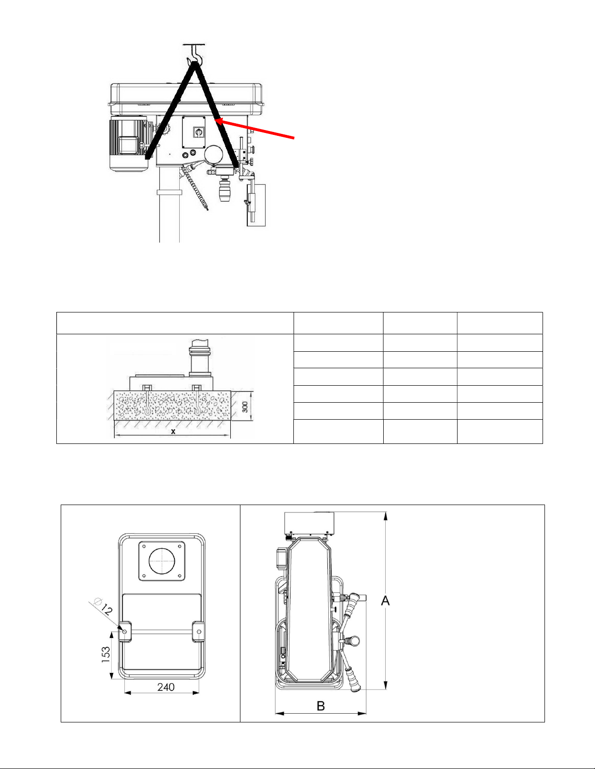
7-4. It shall be stable and securely fixed in machine installation procedure for the machine to be used safely.
7-5. The working piece must be tightly fixed on table by vise or clamp.
7-6. Use recommended cutting liquid; consult the owner’s manual for recommendation.
7-7. Feed speed should be executed under safety scope, please refer to manual 3-3.
7-8. Wear proper apparel, no loose clothing, gloves, neckties, ring, and bracelet during operation. Always
wear safety glasses, cap and specific clothes.
7-9. Check all parts are in place and securely locked before transportation. Bump and crash are prohibited.
7-10. Regular maintenance and repaired should be executed in accordance with the rules of manual.
7-11. Use the industrial suction to clean the chip is recommended.
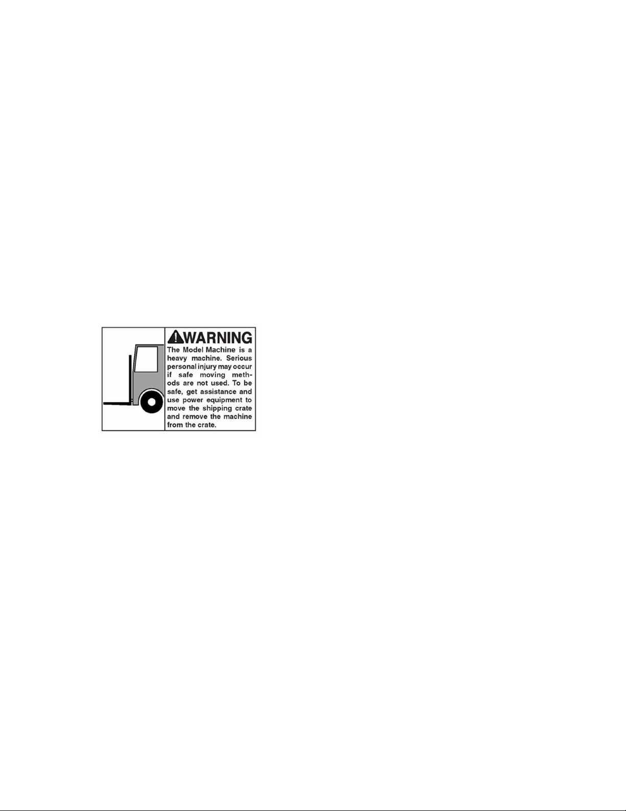
7-12. Use carrier to move the working piece which the weight is more than 10 kg is recommended.
7-13. Wear safety gloves when install the drilling bit or tooling to avoid hurting your hand is recommended.
7-14. This machine only be used following material brass, cast iron, steel, iron, aluminum.
7-15. It is prohibited to open the pulley cover during operation.
7-16. It is prohibited to use damaged or cracked parts.
7-17. It is prohibited to remove the guard cover away during operation.
7-18. It is prohibited to move the table when machine is during operation.
7-19. It is prohibited to operate this machine beyond the limit of its capacity.
7-20. Refer to this instruction for details.
7-21. It is prohibited to insert one's hand or finger into the hole of working piece during operation.
7-22. It is prohibited all visitors and children should stand near work area while the machine during operation.
7-23. It is prohibited to wear gloves, neckties, ring, bracelet and loose clothing during operation.
7-24. It is prohibited to use plastic and wooden working.
7-25. Check again before switch on power:
A- Make sure the power voltage is for the machine.
B- Make sure the machine is completely assembled and installed
C- Make sure chuck, working table, working piece are completely secured or tightly fixed.
D- Make sure the chuck key is removed from chuck.
E- Make sure drill bit or tooling need to be fixed in the chuck.
7-26. Switch off power at once:
A- When fix or remove working piece.

9
B- When the normal maintenance, service, adjustment or repairing.
C- When the operator leaves the machine.
D- When correct work table adjustment and depth position.
E- When change or remove the drilling bit or tooling.
7-27. Working temp.5 --- 40℃, Humidity 40--- 50, Elevation 0 ---1000 M
Storage temp -25--- 55℃
7-28. Operate location diagram for reference.
Diagram 1 Diagram 2
MODEL Ultimate loading
378VTE 30 kg

10
8. Control panel instruction
A. min-1 or /min (R.P.M.) Indicator
B. Drill / Tap Switch
C. Speed Control Switch
D. Emergency Stop Button
E. Feed Depth Indicator
F. Fault Light
G. Start Button
H. Power Light
I. Stop Button
J. LED Work Lamp Switch (Option)
1. Check the power source
Push the start button to judge the motor and spindle shaft is in normal condition or not.
2. Spindle speed adjustment is controlled by the speed control switch. The speed will be showed out
in the electronic digital meter.
3. If it needs to stop urgently, just push the emergency stop switch.
4. Drill / Tap switch: For changing the machine to Drill Mode or Tap Mode.
J

11
9. Operation illustration and procedure
9-1. There are four T grooves in the worktable. It is used to fix the work piece.
9-2.There is a T grooves in the base, too. It is convenient for fixing the longer, heavier and larger working
piece.
(Option)
9-3.
These machines have special design for tapping, a quick change device. During tapping, if you want
spindle to turn reversely and withdraw tapping tip, just pull up grip handle only (as shown in Figure 12.) If you
want to continue to operate, just press down grip handle. (as shown in Figure 13.)
9-4.Protect safety guard shall be allocated in a proper position in operation. It is controlled by a micro witch.
Figure 12 (For CE)
Figure 12 Figure 13
Lock Loose

12
9-5. Adjustment of feeding limit
To prevent unwanted penetration to work piece, the feeding limit shall
be set by adjusting the appropriate position of feeding depth fixing button
as long as the
distance between the end of tool and top surface if work
piece is measured.
A. Setting of feeding depth Feed Depth Adjustment
9-6. Adjust work table position
(1)Firstly, loose the clamp handle in left hand (Figure 19)
(2)Then swing the table handle to properly position. (Figure 20)
(3)Finally tight the clamp handle. (Figure 19)
A
Figure 19 Figure 20

13
10. Operation tips and sound pressure
Speed Selection
Opening the pulley cover is for Hi-Lo speed change only.
The spindle speed is adjusted by speed control switch ”C”.
Recommended
Drill
m/m
Material
Cast Iron Steel Iron Aluminum Alloy Copper
2 4780
2390
1275
635
3980
1910
7960
3980
4460
2230
3 3185
1590
850 425
2650
1275
5310
2655
2970
1485
4 2390
1195
640 320
1990
955 3980
1990
2230
1115
5 1910
955 510 255
1590
765 3185
1590
1785
890
6 1590
795 425 210
1330
640 2655
1330
1485
745
7 1365
680 365 180
1140
545 2275
1140
1275
635
8 1195 600 320 160
995
480 1990
995
1115
555
9 1060
530 285 140
885
425 1770
885
990 495
10 955 480 255 125
800
380 1590
800
890 445
11 870 435 230 115 725
350 1450
725
910 405
12 795 400 210 105
665
320 1330
665
745 370
13 735 365 195 100
610
295 1225
610
685 340
14 680 340 180 90 570
270 1135
570
635 320
15 640 320 170 85 530
255 1060
530
600 300
16 600 300 160 80 500
240 995
500
560 280
17 560 280 150 75 470
225 935
470
525 260
18 530 265 140 70 440
210 885
440
495 250
19 500 250 135 67 420
200 835
420
470 235
20 480 240 130 65 400
190 795
400
445 225
25 380 190 100 50 320
155 640
320
355 180
30 320 160 85 45 265
130 530
265
300 150
40 240 120 65 30 200
95 400
200
225 110
note Processing is adjustable on the cutting materials as well as the material of the cutting to real cutting conditions.
A- weighted sound pressure level measuring under no load
Drilling-series Operator position Lpa= 62 dB(A)

14
378VTE
1. Loosen knob B on both sides of headstock.
2. Push handle A forward as arrow sign to get belt tension.
3. Lock knob B firmly to fix belt tension.
When speed change is required. Loosen lead bolt (parts no. 22-S2) on both side of headstock. Pull belt handle
(parts no. 26) to allow belts repositioning and then move belts to correct groove to acquire desired speed. The
speed chart is above this instruction in the manual.
For proper belt tension, use 10 lbs pressure or hand pressure on the belt as shown as bellow. The
recommended distance is about 70mm.
Models belt model tables
Machine model Belt specifications Quantity
378VTE 6PJ 430 1
B
A
70mm

15
11. Withdraw drill bit
6
1. Bracket bar.
4. Completely insert bracket bar and ready for operating.
2. Setting hole for bracket bar 4-1. Rotate the spindle until the inner drift-
key slot is aligned with the
outer slot, as shown in (Figure 4-1
). You will see through the
spindle when the slot is properly aligned.
3. Insert bracket bar into setting hole 5. Recommend to use special designed wedge for withdrawing tooling
6. Don't push spindle stroke too long to avoid spindle stick.
4
-
1
Both Slots
Aligned

16
12. Trouble – Shooting
Warning: Switch off power and remove plug from power source outlet before trouble
shooting.
NO.
SYMPTOM DISPOSITION
1
Drill insert in working piece and
spindle shaft stop
1. Push emergency button
2. Turn off the power
3. Use hand to turn the spindle shaft countermarch.
Let the tool withdraw from the working piece.
4. Suction the chip on the hole.
5. Turn on power again.
6. Adopt slowly feed make sure in normal condition
then recovery the normal feed.
2
Cutting liquid in abnormal
condition and can not supply
the adequate quantity.
1. Check the pump is running or not
2. Check if the hose is leaking or not.
3 Spindle shaft can not running
completely
1. Check the belt tension condition
2. If belt tension is too loose, adjust the belt shifter,
otherwise change the aging belt.
4 Motor do not work
1. Check the power and switch
2. Check the power cable is damaged or not if cable
is broken, change it directly.
5 Spindle shaft has noise
1. Check bearing
2. Check V – belt, if tightly degree over specific
tension will cause noise.
6 Drill oscillation 1. Check chuck condition
2. Make sure the drill is properly fixed in the chuck.
7 Pump stop suddenly or slow
down
1. Impeller is clogged.
2. Overloading protection device of motor starts.
3. Motor failure.

17
13. Maintenance
Warning: Switch off power and remove plug from power source outlet before
maintenance.
`
NLGI #2 grease
oil
ISO 68 LUBRICANT
Everyday
1 week
1 Month
1 Month

18
14. Feed Shaft Spring Tension
The feed shaft return spring is adjusted at the factory; however, during the life of the drill press you may want to
adjust the feed shaft return spring so the feed shaft return pressure suits your operating needs.
To adjust the feed shaft spring tension:
1. UNPLUG THE DRIL PRESS !
2. Wipe off any oil on the spring lock cover so it does not slip in your fingers when you hold the cover from
spinning (see Figure 28).
While holding the spring lock cover against the side of the head stock so the cover stays splined with the
locking lug; loosen the jam nut and loosen the cover nut approximately 14" (see Figure 30).
Put on heavy leather gloves to protect your hands from possible lacerations if the spring uncoils during the
next step.
Pull the cover outward just enough to disengage the spring-cover lock slot from the locking lug. Note: It is
important to keep a good grip during this step. Letting go of the cover will cause the spring to rapidly uncoil.
Rotate the cover counterclockwise to increase spring tension, or let the cover slowly unwind in the clockwise
direction to reduce spring tension.
Engage the next available spring-cover lock slot with the locking lug and hold the spring lock cover tightly
against the side of the headstock.
Snug the cover nut against the spring cover just until the nut stops, and then back off the nut approximately
13 turn, or just enough so there is no binding at complete spindle travel.
Hold the cover nut and tighten the jam nut against the cover nut.
Figure
27
Figure 29 Figure 30
Figure 28
Lock Nut
Spring Lock
Cover
Spring Cover
Lock Slot
Screw
Wrench
Size 19mm
Table of contents
Other Promac Power Tools manuals

Promac
Promac 930ELB User manual

Promac
Promac JD-32120 User manual

Promac
Promac 213A User manual

Promac
Promac JD-3285-M User manual

Promac
Promac 212 User manual

Promac
Promac 378CLB User manual

Promac
Promac 930VLB User manual

Promac
Promac 214AB-M User manual

Promac
Promac 212VLL User manual

Promac
Promac 378VB User manual