Promac JD-3285-M User manual

3
GB - ENGLISH
Operating Instructions
Dear Customer,
Many thanks for the confidence you have shown in us with the purchase of your new PROMAC-machine. This manual has been
prepared for the owner and operators of a JD-3285-M or JD-3285-T drill press to promote safety during installation, operation
and maintenance procedures. Please read and understand the information contained in these operating instructions and the
accompanying documents. To obtain maximum life and efficiency from your machine, and to use the machine safely, read this
manual thoroughly and follow instructions carefully.
…Table of Contents
1. Declaration of conformity
2. Warranty
3. Safety
Authorized use
General safety notes
Remaining hazards
4. Machine specifications
Technical data
Noise emission
Contents of delivery
5. Transport and start up
Transport and installation
Assembly
Mains connection
Starting operation
6. Machine operation
7. Setup and adjustments
Removing the chuck and arbor
Adjusting the depth stop
Changing spindle speeds
Table tilt adjustment
Return spring adjustment
Cross Laser Adjustment
LED Work Light Adjustment
8. Maintenance and inspection
9. Trouble shooting
10. Environmental protection
11. Available accessories
1. Declaration of conformity
On our own responsibility we hereby
declare that this product complies with
the regulations* listed on page 2.
Designed in consideration with the
standards**.
2. Warranty
TOOL FRANCE SARL guarantees that
the supplied product(s) is/are free from
material defects and manufacturing
faults.
This warranty does not cover any
defects which are caused, either
directly or indirectly, by incorrect use,
carelessness, damage due to
accidents, repairs or inadequate
maintenance or cleaning as well as
normal wear
and tear.
Further details on warranty (e.g.
warranty period) can be found in the
General Terms and Conditions (GTC)
that
are an integral part of the contract.
These GTC may be viewed on the
website of your dealer or sent to you
upon request.
TOOL FRANCE SARL reserves the
right to make changes to the product
and accessories at any time.
3. Safety
3.1 Authorized use
This drill press is designed for drilling
wood and machinable metal and
plastic materials only. Machining of
other materials is not permitted and
may be carried out in specific cases
only after consulting with the
manufacturer.
Never cut magnesium-
high danger of fire!
The workpiece must allow to safely be
loaded and clamped for machining.
The proper use also includes
compliance with the operating and
maintenance instructions given in this
manual.
The machine must be operated only by
persons familiar with its operation and
maintenance and who are familiar with
its hazards.
The required minimum age must be
observed.
The machine must only be used in a
technically perfect condition.
When working on the machine, all
safety mechanisms and covers must
be mounted.
In addition to the safety requirements
contained in these operating
instructions and your country’s
applicable regulations, you should
observe the generally recognized
technical rules concerning the
operation of wood- and metal-working
machines.
Any other use exceeds authorization.
In the event of unauthorized use of the
machine, the manufacturer renounces
all liability and the responsibility is
transferred exclusively to the operator.
3.2 General safety notes
Drill press can be dangerous if not
used properly. Therefore the
appropriate general technical rules as
well as the following notes must be
observed.
Read and understand the entire
instruction manual before attempting
assembly or operation.
Keep this operating instruction close
by the machine, protected from dirt
and humidity, and pass it over to the
new owner if you part with the tool.

4
No changes to the machine may be
made.
Daily inspect the function and
existence of the safety appliances
before you start the machine.
Do not attempt operation in this case,
protect the machine by unplugging the
power cord.
Before operating the machine, remove
tie, rings, watches, other jewellery, and
roll up sleeves above the elbows.
Remove all loose clothing and confine
long hair.
Wear safety shoes; never wear
leisure shoes or sandals.
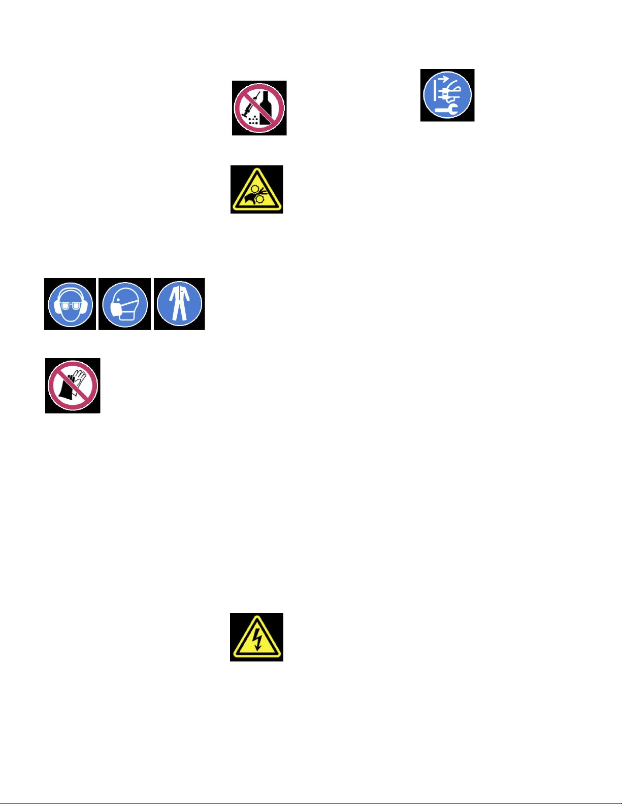
Always wear the approved working
outfit:
- safety goggles
- ear protection
- dust protection
Do not wear gloves while operating
this machine.
Install the machine so that there is
sufficient space for safe operation and
workpiece handling.
Keep work area well lighted.
The machine is designed to operate in
closed rooms and must be bolted
stable on firm and levelled table
surface or on the supplied cabinet
stand.
Make sure that the power cord does
not impede work and cause people to
trip.
Keep the floor around the machine
clean and free of scrap material, oil
and grease.
Stay alert!
Give your work undivided attention.
Use common sense. Do not operate
the machine when you are tired.
Keep an ergonomic body position.
Maintain a balanced stance at all
times.
Do not operate the machine under the
influence of drugs, alcohol or any
medication. Be aware that medication
can change your behaviour.
Never reach into the machine while it
is operating or running down.
Keep children and visitors a safe
distance from the work area.
Never leave a running machine
unattended. Before you leave the
workplace switch off the machine.
Do not operate the electric tool near
inflammable liquids or gases.
Observe the fire fighting and fire alert
options, for example the fire
extinguisher operation and place.
Do not use the machine in a dump
environment and do not expose it to
rain.
Before machining, remove any nails
and other foreign bodies from the
workpiece.
Work only with well sharpened tools.
Machine only stock which rests
securely on the table.
Always close the chuck cover before
you start the machine.
Specifications regarding the maximum
or minimum size of the workpiece must
be observed.
Do not remove chips and workpiece
parts until the machine is at a
standstill.
Do not stand on the machine.
Connection and repair work on the
electrical installation may be carried
out by a qualified electrician only.
Have a damaged or worn power cord
replaced immediately.
Make all machine adjustments or
maintenance with the machine
unplugged from the power source.
Never place your fingers in a position
where they could contact the drill or
other cutting tool if the work piece
should unexpectedly shift or your hand
should slip.
Secure workpiece against rotation.
Use fixtures, clamps or a vice to hold
the workpiece.
Never hold the workpiece with your
hands alone.
Whenever possible, position the work
piece to contact the left side of the
column. If it is too short or the table is
tilted, clamp solidly to the table. Use
the table slots or clamping ledge
around the outside of the table.
When using a drill press vice, always
fasten it to the table.
Never do any works “freehand” (hand-
holding the work piece rather than
supporting it on the table), except
when polishing.
Securely lock the head to the column
and the table bracket to the column
before operating the press.
Never move the head or the table
while the machine is running.
If a work piece overhangs the table
such that it will fall or tip if not held,
clamp it to the table or provide
auxiliary support.
Do not use wire wheels, router bits,
shaper cutters, circle cutters, or rotary
planers on this drill press.
To avoid injury from parts thrown by
the spring, follow instructions exactly
as given when adjusting the spring
tension of the quill.
To avoid injury from parts thrown by
the spring, follow instructions exactly
as given in chapter 7.5.
3.3 Remaining hazards
When using the machine according to
regulations some remaining hazards
may still exist.
The rotating drill bit can cause injury.
Thrown workpieces and workpiece
parts can lead to injury.

5
Dust, chips and noise can be health
hazards. Be sure to wear personal
protection gear such as safety goggles
and dust mask. Use a suitable dust
collection system.
The use of incorrect mains supply or a
damaged power cord can lead to
injuries caused by electricity.
4. Machine specifications
4.1 Technical data
Drilling capacity(Iron/Steel) 32/32mm
Spindle to column 215mm
Spindle travel 85mm
Spindle taper MT-3/B16
Chuck size 16mm
Column diameter 80mm
Table size 290 x 290 mm
Overall height 1050 mm
Number of speeds 16
Range of speeds 180 - 3000 rpm
Net weight 61 kg
JD-3285-M:
Mains 230V ~1/N/PE 50Hz
Output power 0.75 kW (1 HP) S1
Reference current 4.6 A
Extension cord (H07RN-F): 3x1.5mm²
Installation fuse protection 10A
JD-3285-T:
Mains 400V ~3L/N/PE 50Hz
Output power 0.75 kW (1 HP) S1
Reference current 2.4 A
Extension cord (H07RN-F): 5x1.5mm²
Installation fuse protection 10A
4.2 Noise emission
Acoustic pressure level
(according to EN ISO 11202):
Idling LpA 71,8 dB(A)
In operation LpA 84,0 dB(A)
The specified values are emission
levels and are not necessarily to be
seen as safe operating levels.
As workplace conditions vary, this
information is intended to allow the
user to make a better estimation of the
hazards and risks involved only.
4.3 Content of delivery
Head assembly
Table
Column and bracket assembly
Machine base
16mm keyless chuck
MT-3 arbor
3 downfeed handles
Table bracket lock handle
Table bracket rising handle
Drill chuck guard
Drift key
Operating tools
Assembly kit
Operating manual
Spare parts list.
5. Transport and start up
5.1 Transport and installation
The machine is designed to operate in
closed rooms and must be placed
stable on firm and levelled ground. The
machine can be bolted down if
required.
For packing reasons the machine is
not completely assembled.
5.2 Assembly
If you notice transport damage while
unpacking, notify your supplier
immediately. Do not operate the
machine!
Dispose of the packing in an
environmentally friendly manner.
Clean all rust protected surfaces with a
mild solvent.
Attach the column assembly (A, Fig. 1)
to the base (B, Fig. 1) with four M10
hex cap bolts (C, Fig 1). Tighten firmly.
Fig 1
Thread the table bracket lock handle
(A, Fig 2) into the table bracket (B, Fig
2).
Fig 2
Slide the table bracket rising handle
(B, Fig 3) onto the table bracket shaft.
Fig 3
Turn the handle until the set screw is
opposite the flat section on the shaft
and tighten the set screw (A, Fig 3).
Insert the table into the table bracket.
Tighten the table lock handle.
With the aid of a second person,
carefully lift the head onto the column
top.
Caution: The head assembly is
heavy! Use care when lifting onto
the column!
Rotate the head assembly until the
sides of the belt cover are parallel with
the sides of the base.
Tighten two set screws (A, Fig. 4).
Fig 4

6
Install three down feed handles (A,
Fig. 5) into the down feed hub (B).
Fig 5
The Drill Chuck Guard Adjustment
(Fig. 6.1).
Fig 6.1
This clear plastic shield should be
used whenever conducting a drilling or
tapping operation. Clean the safety
shield periodically to provide a clear
view of the work piece. Adjustments
can be done as follows.
1. Adjust the internal cover shield to
have better range protection.
2. If both internal and external
shields cannot provide enough
protection, loosen locking bolt (M)
to shift setting ring (N) in proper
position.
Note: Make sure the bolt (M) aligning
to the groove (aimed by the arrow),
otherwise the interlock switch would
not be triggered when the shields
being opened (Fig. 6.2).
Fig. 6.2
Raise the table to approximately
200mm below the spindle assembly.
Lock the table.
Place a piece of scrap wood on the
table.
Thoroughly clean the spindle opening,
the arbor, and the chuck.
Important:
These three pieces must be free of
any rust protection or lubricant. If they
are not clean, the arbor and chuck will
fail to seat in the spindle and will fall
out.
Place the arbor into the chuck.
Twist the chuck to retract the chuck
jaws if they are exposed.
Place the arbor and chuck assembly
into the spindle.
Turn the arbor and chuck assembly
until the tang on the arbor engages the
slot at the end of the spindle.
Lower the down feed handle so that
the chuck meets the scrap wood.
Pressure on the down feed handle
once the chuck meets the scrap wood
seats the arbor and chuck into the
spindle ( see Fig 7).
Fig 7
5.3 Mains connection
Mains connection and any extension
cords used must comply with
applicable regulations.
The mains voltage must comply with
the information on the machine licence
plate.
The mains connection must have a
10 A surge-proof fuse.
Only use power cords marked H07RN-
F
Connections and repairs to the
electrical equipment may only be
carried out by qualified electricians.
5.4 Starting operation
You can start the machine with the
green on button. The red button on the
main switch stops the machine (Fig.
8).
Fig 8
6. Machine operation
Always adjust the table and the depth
stop to prevent drilling into the table.
Use a back-up piece of scrap wood to
cover the table. This protects both the
table and the drill bit.
Secure workpiece to the table with
clamps or a vice to prevent rotating
with the drill bit.
Feed the bit into the material with only
enough force to allow the drill bit to
work. Feeding too slowly may cause
burning of the workpiece. Feeding too
quickly may cause the motor to stop
and/or the drill bit to break.
Recommended speeds for a 10mm
HSS drill:
Wood: 2000 RPM
Plastic: 1500 RPM
Aluminum: 1500 RPM
Brass: 1500 RPM
Cast iron: 1000 RPM
Mild steel: 800 RPM
High carbon steel: 600 RPM
Stainless steel: 300 RPM

7
Generally speaking, the smaller in
relation the drill bit, the greater the
RPM required.
Wood requires higher speeds than
metal.
Metal is usually drilled at slower
speeds; cutting oil is applied if
necessary.
Warning:
Always keep your hands well clear of
the rotating bit.
Do not remove chips and workpiece
parts until the machine is at a
standstill.
Always close the chuck guard and
pulley cover before you start the
machine.
When using a drill press vice, always
fasten it to the table.
Never do any works “freehand” (hand-
holding the work piece rather than
supporting it on the table), except
when polishing.
Support long workpieces with helping
roller stands.
Do not use wire wheels, router bits,
shaper cutters, circle cutters, or rotary
planers on this drill press.
Never cut magnesium-
high danger of fire!
7. Setup and adjustments
General note:
Setup and adjustment work may
only be carried out after the
machine is protected against
accidental starting by pulling the
mains plug.
7.1 Removing the Chuck and Arbor
Unplug the machine from the power
source.
Lower the quill using the down feed
handle.
Rotate the spindle to align the key in
the spindle with the key hole in the
quill.
Insert the drift key (A, Fig 9) into the
aligned slots and tap lightly. Have
another person (or a protected table)
catch the chuck and arbor assembly
as it falls away from the spindle.
Fig 9
7.2 Adjusting the Depth Stop
To drill multiple holes at the same
preset depth, use the depth stop:
With the drill bit in the chuck, lower the
down feed handle to advance the
chuck to the desired point.
Turn the depth scale collar (C, Fig. 10)
counter-clockwise until it stops moving.
Tighten the depth scale lock (D).
Fig 10
The drill bit will now advance only to
this point.
7.3 Changing Spindle Speeds
Loosen the locking screw on the pulley
cover, then open the cover.
A spindle speed and belt arrangement
chart is found on the inside of the belt
cover (Fig 11). Refer to this chart
whenever changing speeds.
Fig 11
To change spindle speeds:
Unplug the machine from the power
source.
Loosen two side bar bolts found on
each side of the head assembly. (A,
Fig 12).
Fig 12
Rotate the tension adjuster (B) to bring
the motor base as close to the head as
possible.
Change the belts location according
the speed chart and the speed you
desire.
Rotate the tension adjuster (B) to
tension the belts.
Tighten two slide bar bolts (A, Fig. 12).
Belts are properly tensioned when
finger and thumb pressure midway
between the two pulleys causes
approximately 10 mm deflection.
Close and lock the pulley cover.
7.4 Table Tilt Adjustment
Disconnect the machine from the
power source (unplug).

8
Fig 13
Loosen the hex cap bolt (C) to tilt the
table.
Caution:
Only loosen the hex cap bolt slightly,
otherwise the table assembly will
separate from the column and fall.
Tighten the hex cap bolt.
7.5 Return Spring Adjustment
Disconnect the machine from the
power source (unplug).
The return spring is adjusted at the
factory and should not need further
adjustment. If adjustment is necessary:
Unplug the machine from the power
source.
Loosen two lock nuts (A, Fig 14)
approximately 6mm.
Fig 14
Firmly hold the coil spring cover (B).
Pull out the cover and rotate until the
pin (C) on the return spring plate
engages the next notch in the coil
spring cover. Turn the cover clockwise
to decrease tension and counter-
clockwise to increase tension.
Tighten two lock nuts (A). Do not over-
tighten. Nuts should not contact the
housing when tight.
7.6 Cross Laser Adjustment
The lasers are designed for use with
twist drill bits.
There will be shadowing with wider
tools, such as Forstner bits, therefore
use will be limited.
The two laser beams need to meet at
the drill centre (Fig 15).
Fig 15
The Laser Assembly has been
installed and pre-set at the factory.
To adjust, install a small drill bit and
rotate lasers (A, Fig 16) gently with a
set of pliers.
Loosen Screw (C) for adjustment.
ATTENTION:
Class 2 Laser
Do not stare into beam of laser
Do not view directly with optical
instruments
Do not point the laser beam at people
or animals.
Do not use the laser beam on highly
reflective materials. Reflected laser
light is dangerous.
A defective laser beamer may be
replaced only, not repaired.
Fig 16
7.7 LED Work Light Adjustment
The integrated LED work light is
adjustable.
Push on the rim of the light to adjust
(B, Fig 16).
8. Maintenance and inspection
General notes:
Maintenance, cleaning and repair
work may only be carried out after
the machine is protected against
accidental starting by pulling the
mains plug.
Lubrication:
Periodically lubricate the gear and the
rack, the table elevation mechanism,
the drive splines (grooves) in the
spindle, and the teeth of the quill
gently with grease.
Clean the machine regularly.
Defective safety devices must be
replaced immediately.
Repair and maintenance work on the
electrical system may only be carried
out by a qualified electrician.
9. Trouble shooting
Motor doesn’t start
*No electricity-
check mains and fuse.
*Defective switch, motor or cord-
consult an electrician.
Chuck will not stay on spindle
*Oil or grease on contact surfaces-
clean the tapered surfaces of chuck
and spindle.
Machine vibration
*Incorrect belt tension-
Adjust belt tension.
*Dry spindle quill-
lubricate spindle quill.
*Spindle pulley loose-
tighten retaining nut.
*Motor pulley loose-
Tighten set screw.
*dull drill bit-
resharpen drill bit.
Drill bit burns
*incorrect speed-
reduce speed.
*Chips clogged-
retract drill bit frequently
*dull drill bit-
resharpen drill bit.

9
*feeding too slow-
feed faster.
Drill leads off
*cutting lips or angle not equal-
resharpen drill bit correctly.
*drilled hole off center-
drill a pilot hole first.
*bent drill bit-
use a proper drill bit.
*drill bit not properly installed-
install drill bit correctly.
10. Environmental protection
Protect the environment.
Your appliance contains valuable
materials which can be recovered or
recycled. Please leave it at a
specialized institution.
This symbol indicates separate
collection for electrical and electronic
equipment required under the WEEE
Directive (Directive 2012/19/EC) and is
effective only within the European
Union.
11. Available accessories
Refer to the PROMAC-Pricelist.
This manual suits for next models
1
Table of contents
Other Promac Power Tools manuals

Promac
Promac 212 User manual

Promac
Promac 930VLB User manual

Promac
Promac JDT-5030 User manual

Promac
Promac 387AB User manual

Promac
Promac JDT-4024 User manual

Promac
Promac JD-32120 User manual

Promac
Promac 378CLB User manual

Promac
Promac 214AB-M User manual

Promac
Promac 378VTE User manual

Promac
Promac 930ELB User manual