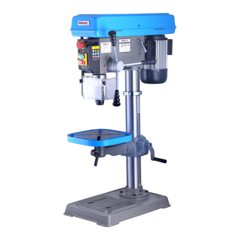
Promac PBM-1839V User manual

08-2017
Milling drilling centre PBM-1839V
Bohr- Fräsmaschine
Perceuse fraiseuse
Schweiz / Suisse
JPW (TOOL) AG
Tämperlistrasse 5
CH-8117 Fällanden Switzerland
www.promac.ch
France
TOOL France / PROMAC
57, rue du Bois Chaland, Z.I. du Bois Chaland
case postale 2935 FR-91029 Evry Cedex
ww
w
.promac.f
r

CE-Conformity Declaration
CE-Konformitätserklärung
Déclaration de Conformité CE
Product / Produkt / Produit:
Milling drilling centre / Bohr-Fräsmaschine / Perceuse fraiseuse
PBM-1839V
Brand / Marke / Marque:
PROMAC
Manufacturer / Hersteller / Fabricant:
JPW (Tool) AG, Tämperlistrasse 5, CH-8117 Fällanden
Schweiz / Suisse / Switzerland
We hereby declare that this product complies with the regulations
Wir erklären hiermit, dass dieses Produkt der folgenden Richtlinie entspricht
Par la présente, nous déclarons que ce produit correspond aux directives suivantes
2006/42/EC
Machinery Directive
Maschinenrichtlinie
Directive Machines
2014/30/EU
electromagnetic compatibility
elektromagnetische Verträglichkeit
compatibilité électromagnétique
designed in consideration of the standards
und entsprechend folgender zusätzlicher Normen entwickelt wurde
et été développé dans le respect des normes complémentaires suivantes
EN ISO 12100:2010
EN 12717:2001+AC:2010, EN 13128:2001+A1 A2
EN 60204-1:2006+A1:2009
EN 55014-1:2006+A2:2011, EN 55014-2:2015
EN 61000-3-2:2014, EN 61000-3-3:2013
Responsible for the Documentation / Dokumentations-Verantwortung / Responsabilité de Documentation:
Hansjörg Meier
Head Product-Mgmt. / Leiter Produkt-Mgmt. / Resp. Gestion des Produits
JPW (Tool) AG
2017-07-06 Alain Schmid, General Manager
JPW (Tool) AG, Tämperlistrasse 5, CH-8117 Fällanden
Schweiz / Suisse / Switzerland

3
EN Operating Instructions (Original)
1.0 About this Manual
This manual is provided by PROMAC, covering the safe operation and maintenance procedures for a PROMAC Model
PBM-1839V Milling machine. This manual contains instructions on installation, safety precautions, general operating procedures,
maintenance instructions and parts breakdown. The machine has been designed and constructed to provide consistent, long-term
operation if used in accordance with the instructions as set forth in this document.
Retain this manual for future reference. If the machine transfers ownership, the manual should accompany it.
2.0 Table of Contents
Section ......................................................................................................................................................................... Page
1.0 About this manual .................................................................................................................................................. 3
2.0 Table of contents..................................................................................................................................................... 3
3.0 Important safety instructions ............................................................................................................................. 4~5
3.1 Designated use and limitations to use ........................................................................................................... 6
3.2 Remaining hazards ......................................................................................................................................... 6
4.0 Specifications ...................................................................................................................................................... 7~8
5.0 Machine description ............................................................................................................................................... 9
6.0 Setup and assembly .............................................................................................................................................. 10
6.1 Unpacking and clean up ................................................................................................................................ 10
6.2 Shipping contents ......................................................................................................................................... 10
6.3 Assembly ...................................................................................................................................................... 10
6.4 Initial lubrication .......................................................................................................................................... 10
6.5 Installation .................................................................................................................................................... 10
7.0 Electrical connections ........................................................................................................................................... 10
7.1 Grounding instructions ................................................................................................................................. 10
7.2 Extension cords ............................................................................................................................................ 10
8.0 Setup and adjustments ......................................................................................................................................... 11
8.1 MT3 Arbour replacement ............................................................................................................................. 11
8.2 Engaging fine feed hand wheel .................................................................................................................... 11
9.0 Operating controls ................................................................................................................................................ 11
10.0 Machining operation ............................................................................................................................................ 12
10.1 Starting spindle rotation ............................................................................................................................... 12
10.2 Recommended spindle speeds ..................................................................................................................... 12
11.0 User maintenance ................................................................................................................................................. 13
11.1 Slide adjustments .......................................................................................................................................... 13
11.2 Lead screw nut adjustments.......................................................................................................................... 13
11.3 Lubrication .................................................................................................................................................... 13
12.0 Troubleshooting .................................................................................................................................................... 14
13.0 Environmental protection ..................................................................................................................................... 14
14.0 Replacement parts .......................................................................................................................................... 15~26
15.0 Wiring diagrams .............................................................................................................................................. 27~28

4
3.0 IMPORTANT SAFETY
INSTRUCTIONS
READ ALL INSTRUCTIONS BEFORE USING THIS MACHINE.
– To reduce risk of injury:
1. Read and understand entire owner’s manual before
attempting assembly or operation of this machine.
2. Read and understand the warnings posted on the
machine and in this manual.
3. Replace warning labels if they become obscured or
removed.
4. This machine is designed and intended for use by properly
trained and experienced personnel only. If you are not
familiar with the proper and safe operation of a milling
and drilling machine, do not use until proper training and
knowledge have been obtained.
5. Do not use this machine for other than its intended use. If
used for other purposes, PROMAC disclaims any real or
implied warranty and holds itself harmless from any injury
that may result from that use.
6. Always wear approved safety glasses or face shield while
using this machine. (Everyday eyeglasses only have impact
resistant lenses; they are not safety glasses.)
7. Before operating this machine, remove tie, rings, watches
and other jewellery, and roll sleeves up past the elbows.
Remove loose clothing and confine long hair. Non-slip
footwear or anti-skid floor strips are recommended. Do
not wear gloves.
8. Wear hearing protection (plugs or muffs) during extended
periods of operation.
9. Some dust created by sawing may contain chemicals
known to cause cancer, birth defects or other
reproductive harm. Some examples of these chemicals
are:
Lead from lead based paint.
Crystalline silica from bricks, cement and other
masonry products.
Arsenic and chromium from chemically treated
lumber.
Your risk of exposure varies, depending on how often you
do this type of work. To reduce your exposure to these
chemicals, work in a well-ventilated area and work with
approved safety equipment, such as face or dust masks
that are specifically designed to filter out microscopic
particles.
10. Do not operate this machine while tired or under the
influence of drugs, alcohol or any medication.
11. Make certain the switch is in the OFF position before
connecting the machine to the power supply. Turn off all
controls before unplugging.
12. Make certain the machine is properly grounded. Connect
to a properly grounded outlet only. See Grounding
instructions.
13. Make all machine adjustments or maintenance with the
machine unplugged from the power source.
14. Remove adjusting keys and wrenches. Form a habit of
checking to see that keys and adjusting wrenches are
removed from the machine before turning it on.
15. Keep safety guards in place at all times when the machine
is in use. If removed for maintenance purposes, use
extreme caution and replace the guards immediately after
maintenance is complete.
16. Check damaged parts. Before further use of the machine,
a guard or other part that is damaged should be carefully
checked to determine that it will operate properly and
perform its intended function. Check for alignment of
moving parts, binding of moving parts, breakage of parts,
mounting and any other conditions that may affect its
operation. A guard or other part that is damaged should
be properly repaired or replaced.
17. Provide for adequate space surrounding work area and
non-glare, overhead lighting.
18. Keep the floor around the machine clean and free of scrap
material, oil and grease.
19. Keep visitors a safe distance from the work area. Keep
children away.
20. Make your workshop child proof with padlocks, master
switches or by removing starter keys.
21. Give your work undivided attention. Looking around,
carrying on a conversation and “horse-play” are careless
acts that can result in serious injury.
22. Keep an ergonomic body position. Maintain a balanced
stance at all times so that you do not fall or lean against
the chuck or other moving parts. Do not overreach or use
excessive force to perform any machine operation.
23. Use the right tool at the correct speed and feed rate. Do
not force a tool or attachment to do a job for which it was
not designed. The right tool will do the job better and
safer.
24. The machine is intended for indoor use. To reduce the risk
of electric shock, do not use outdoors or on wet surfaces.
25. Do not handle plug or machine with wet hands.
26. Use recommended accessories; improper accessories may
be hazardous.
27. Maintain tools with care. Keep tools sharp and clean for
the best and safest performance. Follow instructions for
lubricating and changing accessories.
28. Turn off machine and disconnect from power before
cleaning. Use a brush or compressed air to remove chips
or debris; do not use bare hands.
29. Do not stand on the machine. Serious injury could occur if
the machine tips over.
30. Never leave the machine running unattended. Turn the
power off and do not leave the machine until it comes to
a complete stop.
31. Remove loose items and unnecessary work pieces from
the area before starting the machine.
32. Pull the mains plug if the machine is not in use.
33. Make sure the workpiece is securely clamped.
5
Familiarize yourself with the following safety notices used in this manual:
WARNING: This means that if precautions are not heeded, it may result in serious, or possibly even fatal, injury.
CAUTION: This means that if precautions are not heeded, it may result in minor injury and/or possible machine
damage.
SAVE THESE INSTRUCTIONS
WARNING:
These symbols below advise that you follow the correct safety procedures when using this machine.
Read and understand the entire user
manual before attempting assembly or
machine operation.
Always wear approved working outfit
Wear safety goggles.
Wear ear protection.
Always wear the approved working outfit
Wear safety shoes.
Remove tie, rings, watches, jewellery.
Roll up sleeves above elbows.
Remove all loose clothing and confine
long hair
Make all machine adjustments or
maintenance with the machine unplugged
from the power source.
Do not operate this machine under the
influence of drugs, alcohol or medication
Do not wear gloves while operating this
machine
Connection and repair work on the
electrical installation may be carried out by
a qualified electrician only.
Never reach into the machine while it is
operating or running down.

6
3.1 Designated use and limitations to use
The machine is designed for milling and drilling machinable metal and plastic materials only.
The workpiece must allow to safely be loaded, supported and clamped.
The machine is intended for indoor use. The protection rating of the electrical installation is IP 54.
To avoid tipping, the machine must be bolted down with four anchor bolts.
If used for other purposes, PROMAC disclaims any real or implied warranty and holds itself harmless from any injury that may result
from that use.
WARNING:
The machine is not suitable for machining magnesium…high danger to fire!
Never place your fingers in a position where they could contact any rotating parts or chips.
Check the save clamping of the work piece before starting the machine.
Check the save clamping of the cutting tool before starting the machine.
Do not exceed the speed limit of tools and tool holders.
Choose a low speed when using unbalanced tools.
Do not use wire wheels or grinding wheels on this machine.
Use the right tool at the correct speed and feed rate. Do not force a tool or attachment to do a job for which it was not designed. The
right tool will do the job better and more safely.
Use recommended accessories; improper accessories may be hazardous.
Maintain tools with care. Keep cutting tools sharp and clean for the best and safest performance.
Follow instructions for lubricating and changing accessories.
Do not attempt to adjust or remove tools during operation.
Remove cutting chips with the aid of an appropriate chip hook when the machine is at a standstill only.
Measurements and adjustments may be carried out when the machine is at a standstill only.
Maintenance and repair work may only be carried out after the machine is protected against accidental starting, pull the mains plug.
Remove loose items and unnecessary work pieces from the area before starting the machine.
Tighten all locks before operating.
3.2 Remaining hazards
When using the machine according to regulations some remaining hazards may still exist.
Rotating chuck, tool and cutting chips can cause injury.
Thrown workpieces and workpiece parts can lead to injury.
Hot work pieces and cutting chips can lead to injury.
Tipping of the workpiece due to insufficient support can lead to injury.
Dust, chips and noise can be health hazards. Be sure to wear personal protection gear such as safety goggles, dust mask and ear
protection.
The use of incorrect mains supply or a damaged power cord can lead to injuries caused by electricity.

7
4.0 Specifications
Model number ..........................................................................................................................................................................PBM-1839V
Stock number ……………………………………………………………………................................................................................................. 1000-004-068
Motor and electricals:
Motor type …………………………………………………........................................................................................................................... DC motor
Motor power ..............................................................................................................................................................................0.75 kW
Main power supply ......................................................................................................................................................1~230V, PE, 50Hz
Protection class .......................................................................................................................................................................................I
Listed load amps ..............................................................................................................................................................................3.5 A
Capacities:
Drilling capacity steel St37 ................................................................................................................................................................ 20mm
Milling capacity of face mill .............................................................................................................................................................. 50mm
Milling capacity of end mill ............................................................................................................................................................... 16mm
Spindle:
Spindle taper .....................................................................................................................................................................................MT3
Draw bar .......................................................................................................................................................................................... M12
Spindle travel ................................................................................................................................................................................68 mm
Number of spindle speeds .......................................................................................................................................................... variable
Range of spindle speeds ............................................................................................................................................... 100 ~ 2000 /min
Milling head:
Distance spindle to column .........................................................................................................................................................190 mm
Distance spindle to table ....................................................................................................................................................80 ~ 340 mm
Head travel Z-axis .......................................................................................................................................................................260 mm
Table and Slides:
Table size .......................................................................................................................................................................... 595 x 140 mm
Table travel X-axis .......................................................................................................................................................................395 mm
Table travel Y-axis .......................................................................................................................................................................180 mm
Table slots, number of slots ...................................................................................................................................................................3
Table T-slot size ............................................................................................................................................................................ 12mm
Table T-slot distance .....................................................................................................................................................................35 mm
Materials:
Milling head, table, slides ........................................................................................................................ Cast iron, precision machined
X, Y, Z slide adjustment ................................................................................................................................................... via tapered gib
Spindle bearings ...............................................................................................................................Taper roller bearing & ball bearing
Sound emission in idle 1 ..................................................................................................................................................... 74.4 dB (LpA)
Sound emission during machining 1.................................................................................................................................... 79.3 dB (LpA)
1Sound emission measured according to EN ISO 11202, in 1m distance, 1.6m above ground. The specified values are emission levels
and are not necessarily to be seen as safe operating levels. As workplace conditions vary, this information is intended to allow the user
to make a better estimation of the hazards and risks involved only.
Dimensions and Weights:
Overall dimensions, assembled (W x D x H) .............................................................................................................790 x 640 x 855 mm
Shipping dimensions (W x D x H) ............................................................................................................................ 820 x 720 x 890 mm
Net weight (approximate) ............................................................................................................................................................ 110 kg
Shipping weight (approximate) ..................................................................................................................................................... 130 kg
L = length; W = width; H= height; D= depth
The specifications in this manual were current at time of publication, but because of our policy of continuous improvement, PROMAC
reserves the right to change specifications at any time and without prior notice, without incurring obligations.

8
Table T-slot size:
Figure 4-1: Table T-slot size
Anchor bolt hole pattern:
Figure 4-2: Anchor bolt hole pattern
WARNING:
To avoid tipping, the machine must be bolted down with four anchor bolts (not provided).
7
35
20
1
5

9
5.0 Machine Description
Figure 5-1: Machine description
A ...................................................... Draw bar cover
B .................................................. Z-axis hand wheel
C .................................................Fine feeding wheel
D ................................. Fine feed engagement knob
E ................................................. Down feed handle
F ..................................................X-axis hand wheel
G .................................................... Y- axis slide lock
H .................................................... X- axis slide lock
I .................................................. Y- axis hand wheel
J ..................................................... Drill chuck guard
K .............................................Spindle control panel
L .........................................................Depth display
M ..................................................... Z-axis slide lock
N .....................................................Quill lock screw

10
6.0 Setup and Assembly
WARNING:
Read and understand the entire contents of this manual
before attempting assembly or operation. Failure to comply
may cause serious injury.
6.1 Unpacking and clean up
Remove all contents from shipping crate and compare parts to
the contents list in this manual. If shipping damage or any part
shortages are identified, contact your distributor. Do not
discard crate or packing material until drill press is assembled
and running satisfactorily.
Clean all rust protected surfaces with kerosene or a light
solvent. Do not use lacquer thinner, paint thinner or gasoline,
as these can damage plastic components and painted surfaces.
6.2 Shipping contents
1 Machine
1 Draw bar M12
1 Chuck guard
1 Operating tools
1 Operating instructions and parts manual
6.3 Assembly
The machine comes completely assembled.
Attach the crank handles to the hand wheels (B, F, I, Fig 5-1).
Inspect that all fasteners are tight.
6.4 Initial lubrication
The machine must be serviced at all lubrication points before it is
placed into service (see chapter 11.1 for lubrication).
6.5 Installation
Unbolt the machine from the shipping crate bottom.
Use heavy duty fibre belt for lifting the machine off the pallet.
WARNING:
The machine is heavy (110 kg)!
Assure the sufficient load capacity and proper condition of your
lifting devices.
Never step underneath suspended loads.
To avoid tipping, the machine must be bolted down with four
anchor bolts (not provided).
To avoid twisting the bed, make sure the setup surface is
absolutely flat and level.
Loosen anchor bolts, shim and tighten bolts if needed.
The machine must be level to be accurate!
7.0 Electrical Connections
WARNING:
All electrical connections must be done by a qualified
electrician in compliance with all local codes and ordinances.
Failure to comply may result in serious injury.
The PBM-1839V Milling Drilling Centre is rated at 1~230V,
50Hz power supply. The machine comes with a plug designed
for use on a circuit with a grounded outlet.
Mains connection and any extension cords and plugs used
must comply with the information on the machine license
plate.
The mains connection must have a 16A surge-proof fuse.
Only use extension cords marked H07RN-F, with wires 1,5mm2
or more.
The total length of cord may not exceed 18 Meter
Power cords and plugs must be free from defects.
Connections and repairs to the electrical equipment may only
be carried out by qualified electricians.
The machine is equipped with 1.8m power cord and plug.
Before connecting to power source, be sure main switch is in
off position.
7.1 Grounding instructions
This tool must be grounded. In the event of a malfunction or
breakdown, grounding provides a path of least resistance for
electric current to reduce the risk of electric shock. This tool is
equipped with an electric cord having an equipment-
grounding conductor and a grounding plug. The plug must be
inserted into an appropriate outlet that is properly installed
and grounded in accordance with all local codes and
ordinances.
WARNING:
Improper connection of the equipment-grounding conductor
can result in a risk of electric shock. Check with a qualified
electrician or service person if you are in doubt as to whether
the outlet is properly grounded. Do not modify the plug
provided with the tool.
The green/yellow conductor is the equipment-grounding
conductor. If repair or replacement of the electric cord or plug
is necessary, do not connect the equipment-grounding
conductor to a live terminal.
Use only 3-wire extension cords with grounding plugs.
Repair or replace damaged or worn cord immediately.
7.2 Extension cords
The use of extension cords is discouraged; try to position
machines near the power source. If an extension cord is
necessary, make sure it is in good condition.

11
An undersized cord will cause a drop in line voltage resulting in
loss of power and overheating.
Only use extension cords marked H07RN-F, with wires 1,5mm2
or more.
The total length of cord may not exceed 18 Meter
Extension cords and plugs must be free from defects.
8.0 Setup and Adjustments
8.1 MT3 Arbour replacement
Remove the draw bar cover (X, Figure 8-1).
Figure 8-1: MT3 Arbor replacement
Stop spindle rotation with the supplied spanner.
Loosen the draw bar with a hex socket wrench (Y).
Loosen the drawbar by 2 to max 3 full turns.
Tap the drawbar head with a rubber mallet to dislodge the
MT3 tool taper.
8.2 Engaging the fine feed hand wheel
To activate the fine feed hand wheel (C, Figure 8-2) tighten the
engagement knob (F).
Figure 8-2: Engage fine feed hand wheel
9.0 Operating Controls
Refer to Figure 9-1:
N .................................................. Speed control knob
O ...............................................
Rev / OFF/ Fwd switch
P ................................... Overload and Not-ready lamp
Q ..............................................
Emergency stop switch
R ................................................. Spindle speed display
Figure 9-1: Operating Controls
Refer to Figure 9-2:
AA ................................................ Change mm to Inch
BB ...................................................................ON/OFF
CC .................................................... set display to “0”
DD ............................................battery compartment
(slide to right to open….battery type SR 44 or LR 44 ).
Figure 9-2: Drill Depth Display

12
10.0 Machining Operation
CAUTION:
Never place your fingers in a position where they could
contact any rotating tool, chuck or cutting chips.
Remove cutting chips with the aid of an appropriate chip hook
when the machine is at a standstill only.
Never stop the rotating chuck or tool with your hands.
Always close the chuck guard before you start the machine.
Secure work piece to the table with clamps or a vice to prevent
rotating with the drill bit.
When using a vice, always fasten it to the table.
Check the save clamping of the work piece, chuck and tools
before starting the machine.
Never do any works “freehand” (hand-holding the work piece
rather than supporting it on the table).
Support long work pieces with helping roller stands.
Always adjust the depth stop to prevent drilling into the table
or into the work holding device.
Feed a drill bit into the material with only enough force to
allow the drill bit to work.
Feeding too slowly may cause burning of the work piece or
tool. Feeding too quickly may cause the motor to stop and/or
the drill bit to break.
Do not use wire wheels or grinding wheels on this machine.
Never cut magnesium - high danger to fire!
Measurements and adjustments may be carried out when the
machine is at a standstill only.
In case of danger push the emergency stop button.
10.1 Starting spindle rotation
Before starting the machine check the proper workpiece
clamping and cutting tool setup.
Close the chuck guard before you start the machine.
Make sure the Rev / Power-OFF/ Fwd switch (O, Figure 9-1) is
in OFF position before you connect the machine to the power
supply.
Digital spindle speed display (R, Figure 9-1) is illuminated when
connected.
Use the Rev / Power-OFF/ Fwd switch (O, Figure 9-1) to select
the spindle rotating direction and to energize the electrics.
Start the machine with the Speed control knob (N, Figure 9-1).
Stop the machine by turning the knob counter-clockwise until
it clicks into OFF position.
The emergency stop button (Q, Figure 9-1) stops all machine
functions.
Turn emergency stop button clockwise to reset.
Unplug the machine if not in use.
10.2 Recommended spindle speeds
CAUTION:
Generally speaking, the smaller the tool diameter, the greater the
RPM required. Soft materials require higher speeds; hard metals
slower speeds.
Metal is usually machined at slower speeds and cutting oil is
applied.
These are recommended speeds for a 10mm high speed steel
(HSS) tool (e.g. drill bit).
Plastic .................................................................... 2000 /min
Aluminium ............................................................. 2000 /min
Brass ...................................................................... 1000 /min
Cast iron ................................................................ 1000 /min
Mild steel ................................................................ 800 /min
High carbon steel .................................................... 600 /min
Stainless steel ......................................................... 300 /min
For carbide tools (HM), 5 times higher speeds can be chosen.
For example:
Milling mild steel with an end mill of 20mm allows a speed of:
With HSS tool .......................................................... 400 /min
With carbide tool .................................................. 2000 /min

13
11.0 User-Maintenance
WARNING:
Before any intervention on the machine, disconnect it from
electrical supply, pull the mains plug. Failure to comply may
cause serious injury.
An important security factor is the cleaning of the machine, of
Table and slides, of the floor and the surrounding places.
Loose objects could come into contact with the moving tool or
workpiece, creating hazards.
Check that bolts are tight and electrical cords are in good
condition. If an electrical cord is worn, cut, or damaged in any
way, have it replaced immediately.
Repair and maintenance work on the electrical system may
only be carried out by a qualified electrician.
Motor brushes:
The motor brushes are due to wear and need to be replaced
when shorter than 12mm.
Set of brushes: Article No. JMD2S-1-80-SB
11.1 Slide adjustments
All slides (X/Y/Z) are fitted with tapered gibs.
If adjustment is needed, loosen the adjust screws (33, Fig 6)
Adjust by approximately a quarter turn.
Tighten the adjust screws (33) again.
Try and repeat until slides move freely without play.
Figure 11-2: Slide and lead screw Adjustments
11.2 Lead screw nut adjustments
The X/Y lead screws are fitted with adjustable (slotted) lead
screw nuts.
Tighten the screws (32, Figure 11-2) to remove the play.
11.3 Lubrication
The spindle bearings are pre-lubricated and sealed, and
require no further lubrication.
Unpainted surfaces must be protected from corrosion; apply a
thin coat of machine tool oil regularly.
Weekly apply oil:
DIN 51502 CG ISO VG 68
(e.g. BP Maccurat 68, Castrol Magna BD 68, Mobil Vectra 2)
X/Y -axis lead screw ...................... apply oil on entire length.
X/Y/Z -axis hand wheels ..........................lubricate ball oilers.
X/Y/Z -axis ways ...................lubricate ways on entire length.
Spindle quill .................................. apply oil on entire length.
Refer to the Pricelist for various accessories.

14
12.0 Troubleshooting
Symptom Possible Cause Correction *
Motor will not start.
Machine unplugged from wall. Check all plug connections.
Fuse blown, or circuit breaker tripped. Replace fuse, or reset circuit breaker.
Cord damaged. Replace cord.
Chuck guard not closed. Close chuck guard.
Motor brushes worn Replace brushes
Spindle does not come up to
speed.
Extension cord too light or too long. Replace with adequate size and length cord.
Low current. Contact a qualified electrician.
Machine vibrates excessively.
Base on uneven surface. Locate machine on even floor.
Machine not bolted to the floor Bolt machine to the floor
Unbalanced cutting tool Reduce speed
Workpiece deflection Improve workpiece clamping
Tool deflection Reduce tool length
Slide backlash Adjust slides
Slides running dry Lubricate with oil
Dull tool tip Re-sharpen or change tool
Chip load too high Reduce depth of cut or feed
Noisy operation Spindle quill dry Lubricate with oil
Lead screw nuts have play Adjust X and Y axis nuts
Tool tip burns
Cutting speed too high Reduce spindle speed
Dull tool tip. Re-sharpen or change tool
Dry cutting. Lubricate with oil.
Feeding too slowly. Increase feed rate.
Drill leads off
Cutting lips or angle not equal Re-sharpen drill bit.
Drilled hole off centre Drill a pilot hole first
Bent drill bit. Use a proper drill bit
* WARNING: Some corrections may require a qualified electrician.
Table 1
13.0 Environmental Protection
Protect the environment.
Dispose all packaging material in an environmental friendly manner.
Dispose cutting chips and coolant in an environmentally friendly manner.
Your appliance contains valuable materials which can be recovered or recycled. Please leave it at a specialized institution.

15
14.0 Replacement Parts
PBM-1839V Assembly Breakdown -1

16
PBM-1839V Parts List for Breakdown -1 (1/2)
Index Part
No. No. Description Size Qty.
1 ........... PBM1839BDV-1-01................SPINDLE BOX ........................................................... ..................................... 1
2 ........... GB81885-4-6..........................PHILLIPS HD SCREW ................................................M4 x 6 mm ................... 2
3 ........... JMDX2S-1-03 .........................SPINDLE BELOW OIL SEAL RING I ............................ ..................................... 1
4 ........... JMDX2S-1-04 .........................B16 TAPER SHANK................................................... ..................................... 1
5 ........... TRB-32907 .............................TAPERED ROLLER BEARING .....................................32907 ........................... 1
6 ........... GB617286-5...........................HEX NUT (THIN).......................................................M5 ................................ 2
7 ........... JMDX2S-1-07 .........................FINE FEEDING HANDWHEEL.................................... ..................................... 1
8 ........... JMDX2S-1-08 .........................DISPLAY FIXED SQUARE SCREW .............................. ..................................... 1
9 ........... JMDX2S-1-09 .........................SPINDLE SLEEVE BELOW OIL SEAL RING II............... ..................................... 1
10 ......... GB81885-3-8..........................PHILLIPS HD SCREW ................................................M3 x 8 mm ................. 12
11 ......... JMDX2S-1-11A .......................BASE PLATE ............................................................. ..................................... 1
12 ......... JMDX2S-1-12 .........................DIGITAL DISPLAY MODULE...................................... ..................................... 1
13 ......... PBM1839BDV-1-13................PANEL...................................................................... ..................................... 1
14 ......... JMDX2S-1-14 .........................UP WASHER II.......................................................... ..................................... 1
15 ......... GB81985-5-25........................CROSS RECESSED FLAT HD SCREW..........................M5 x 25 ........................ 1
16 ......... JMDX2S-1-16 .........................BEVEL GEAR............................................................. ..................................... 1
17 ......... JMDX2S-1-17 .........................GEAR SHAFT ............................................................ ..................................... 1
18 ......... JMD2S-1-18............................HANDLE SEAT .......................................................... ..................................... 1
19 ......... GB8941-16.............................CIRCLIP FOR SHAFT .................................................16 ................................. 1
20 ......... JMDX2S-1-19 .........................CLOCK SPRING......................................................... ..................................... 1
21 ......... JMDX2S-1-20 .........................CLOCK SPRING COVER............................................. ..................................... 1
22 ......... PBM1839BDV-1-21................SPINDLE BOX COVER ............................................... ..................................... 1
23 ......... JMDX2S-1-22 .........................BEAR SEAT............................................................... ..................................... 1
24 ......... JMDX2S-1-23 .........................SPINDLE TIMING BELT............................................. ..................................... 1
25 ......... JMD2S-1-25............................MOTOR TIMING PULLEY.......................................... ..................................... 3
26 ......... JMD2S-1-26............................HANDLE LEVER ........................................................ ..................................... 1
28 ......... JMDX2S-1-24 .........................SMALL HANDLE ASSEMBLY ..................................... ..................................... 1
29 ......... JMD2S-1-29............................HANDLE KNOB......................................................... ..................................... 3
30 ......... JMDX2S-1-25 .........................SPINDLE SLEEVE LOCKING SHAFT............................ ..................................... 1
31 ......... JMDX2S-1-26 .........................TIGHTEN THE TOP ROD ........................................... ..................................... 1
32 ......... GB7985-6-14..........................SET SCREW (CYLINDER END) ...................................M6 x 14 mm ................. 1
33 ......... GB7785-6-8............................SET SCREW (FLAT END) ...........................................M6 x 8 mm ................... 1
34 ......... GB30889-8.............................STELL BALL...............................................................8 mm ............................ 3
35 ......... JMDX2S-1-30 .........................LOCKING SMALL SHAFT........................................... ..................................... 1
36 ......... JMDX2S-1-31 .........................WORM LOCKING HANDLE....................................... ..................................... 1
37 ......... JMDX2S-1-32 .........................SPINDLE SLEEVE ...................................................... ..................................... 1
38 ......... JMDX2S-1-33 .........................SHAFT GEAR LEFT SUPPORT FLANGE ...................... ..................................... 1
39 ......... GB7785-6-10..........................SET SCREW (FLAT END) ...........................................M6 x 10 mm ................. 1
40 ......... JMD2S-1-40............................SHAFT GEAR RIGHT SUPPORT FLANGE ................... ..................................... 1
41 ......... GB109679-4-8........................FLAT KEY..................................................................4 x 8 mm....................... 1
42 ......... JMDX2S-1-36 .........................SPINDLE UP DUST GUARD I..................................... ..................................... 1
43 ......... JMDX2S-1-37 .........................SPINDLE UP DUST GUARD II.................................... ..................................... 1
44 ......... GB7085-4-10..........................SOCKET HD SCREW..................................................M4 x 10 mm ................. 3
45 ......... JMDX2S-1-39 .........................ECCENTRIC SLEEVE LOCKING BLOCK ....................... ..................................... 1
46 ......... JMD2S-1-46............................MOTOR SUPPORT PLATE.........................................1/4" x 1/4".................... 1
47 ......... TBB-57001 .............................THRUST BALL BEARING ...........................................12 x 22 x 5 .................... 2
48 ......... JMDX2S-1-41 .........................WORM SHAFT ......................................................... ..................................... 1
49 ......... JMDX2S-1-42 .........................WORM ECCENTRIC SLEEVE ..................................... ..................................... 1
50 ......... JMDX2S-1-43 .........................LOCKING BOLT ASSEMBLY....................................... ..................................... 1
51 ......... GB11986A-3-10 .....................ROUND PIN .............................................................3 x 10............................ 1
52 ......... TBB-51106 .............................THRUST BALL BEARING ........................................... ..................................... 1
53 ......... BB-6006ZZ..............................BALL BEARING .........................................................6006ZZ.......................... 1
54 ......... JMDX2S-1-47 .........................UP WASHER............................................................. ..................................... 1
55 ......... JMDX2S-1-48 .........................SLOTTED ROUND NUT............................................. ..................................... 2
56 ......... GB7085-4-12..........................SOCKET HD SCREW..................................................M4 x 12 mm ................. 6

17
PBM-1839V Parts List for Breakdown -1 (2/2)
Index Part
No. No. Description Size Qty.
57 ......... BB-6007ZZ..............................BALL BEARING .........................................................6007ZZ.......................... 1
58 ......... GB8931-62.............................CIRCLIP FOR HOLE ...................................................62 ................................. 1
59 ......... GB8941-35.............................CIRCLIP FOR SHAFT .................................................35 ................................. 1
60 ......... GB7085-5-16..........................SOCKET HD SCREW..................................................M5 x 16 mm ................. 4
61 ......... JMDX2S-1-54 .........................SPINDLE................................................................... ..................................... 1
62 ......... JMDX2S-1-55 .........................TIMING BELT ..........................................................HTD-385 Z77 ................ 1
63 ......... GB97185-6.............................WASHER ..................................................................6 ................................... 4
64 ......... GB7085-6-14..........................SOCKET HD SCREW..................................................M6 x 14 mm ................. 4
65 ......... JMD2S-1-65............................MAGNET..................................................................6 ................................... 1
66 ......... GB87986-3-8..........................ROLL PIN..................................................................3 x 8 mm....................... 2
67 ......... JMDX2S-1-59 .........................ASSIST SMALL HANDLE............................................ ..................................... 1
68 ......... GB11986A-3-14 .....................ROUND PIN .............................................................3 x 14 mm..................... 1
69 ......... GB81985-3-10........................CROSS RECESSED FLAT HD SCREW..........................M3 x 10 mm ................. 5
70 ......... JMD2S-1-70............................WASHER .................................................................. ..................................... 1
71 ......... JMDX2S-1-63 .........................SPINDLE SLEEVE POSITION SHAFT........................... ..................................... 1
72 ......... GB8941-20.............................CIRCLIP FOR SHAFT .................................................20 ................................. 2
73 ......... JMDX2S-1-65 .........................DISPLAY FIXED BRACKET ......................................... ..................................... 1
74 ......... JMDX2S-1-66 .........................ROUND GEAR SHAFT ADJUST WASHER................... ..................................... 1
76 ......... GB7085-10-16........................SOCKET HD SCREW..................................................M10 x 16 mm ............... 1
77 ......... JMDX2S-1-68 .........................BEVEL WEDGE ......................................................... ..................................... 1
78 ......... JMDX2S-1-69 .........................WEDGE SCREW........................................................ ..................................... 2
79 ......... JMDX2S-1-70 .........................SLEEVE LIMTED WASHER ........................................ ..................................... 1
80 ......... JMD2S-1-80............................DC MOTOR ..............................................................750W............................ 1
............. JMD2S-1-80-SB ......................SET OF BRUSHES for DC MOTOR (not shown) ........ ..................................... 1
81 ......... GB8941-12.............................CIRCLIP FOR SHAFT .................................................12 ................................. 1
82 ......... GB109679-4-25......................FLAT KEY..................................................................4 x 25 mm..................... 1
83 ......... GB7085-4-6............................SOCKET HD SCREW..................................................M4 x 6 mm ................... 2
84 ......... GB81985-6-14........................CROSS RECESSED FLAT HD SCREW..........................M6 x 14 mm ................. 4
85 ......... JMD2S-1-85............................PROBE BRACKET...................................................... ..................................... 1
86 ......... JMDX2S-1-71 .........................ATACHMENT BRACKET............................................ ..................................... 1
87 ......... GB7085-4-40..........................SOCKET HD SCREW..................................................M4 x 40 mm ................. 4
88 ......... GB578186-5-12......................HEX HD SCREW........................................................M5 x 12 mm ................. 3
89 ......... JMD2S-1-89............................PROBE ASSY............................................................. ..................................... 1
90 ......... JMD2S-1-90............................PLUG ....................................................................... ..................................... 2

18
PBM-1839V Assembly Breakdown -2

19
PBM-1839V Parts List for Breakdown -2
Index Part
No. No. Description Size Qty.
1 ........... JMDX2S-2-01 .........................COLUMN ................................................................. ..................................... 1
2 ........... JMDX2S-2-02 .........................METRIC RISE AND DOWN LEADSCREW................... ..................................... 1
3 ........... JMDX2S-2-03 .........................METRIC RISE AND DOWN LOCKING NUT ................ ..................................... 1
4 ........... JMDX2S-2-04 .........................METRIC RISE AND DOWN LEADSCREW NUT ........... ..................................... 1
5 ........... JMDX2S-2-05 .........................COLUMN NUT SUPPORT ......................................... ..................................... 1
6 ........... JMDX2S-2-06 .........................LEADSCREW SUPPORT ............................................ ..................................... 1
7 ........... GB11886-6-16........................TAPER PIN WITH INTERNAL THREAD ......................6 x 16 mm..................... 2
8 ........... GB7085-6-12..........................SOCKET HD SCREW..................................................M6 x 12 mm ................. 2
9 ........... JMDX2S-2-09 .........................RISE AND DOWN SUPPORT SEAT ............................ ..................................... 1
10 ......... JMDX2S-2-10 .........................HANDLE................................................................... ..................................... 1
11 ......... GB617286-8...........................HEX NUT (THIN).......................................................M8 ................................ 1
12 ......... JMDX2S-2-12 .........................HANDLE WHEEL....................................................... ..................................... 1
13 ......... JMDX2S-2-13 .........................SPRING PIECE .......................................................... ..................................... 1
14 ......... JMDX2S-2-14 .........................METRIC RISE AND DOWN SCALE DIAL..................... ..................................... 1
15 ......... GB87986-3-20........................ROLL PIN..................................................................3 x 20 mm..................... 1
16 ......... BB-6001 .................................BALL BEARING .........................................................6001 ............................. 4
17 ......... GB6585-8-55..........................SLOTTED LARGE CHEESE HD SCREW .......................M8 x 55 mm ................. 1
18 ......... GB88986-8.............................HEX LOCKING NUT ..................................................M8 ................................ 1
19 ......... GB109679-4-16......................FLAT KEY..................................................................4 x 16 mm..................... 1
20 ......... JMDX2S-2-20 .........................RISE AND DOWN SHAFT.......................................... ..................................... 1
21 ......... GB87986-3-16........................ROLL PIN..................................................................3 x 16 mm..................... 1
22 ......... GB7085-5-30..........................SOCKET HD SCREW..................................................M5 x 30 mm ................. 4
23 ......... GB578186-5-16......................HEX HD SCREW........................................................M5 x 16 mm ................. 3
24 ......... GB7785-6-10..........................SET SCREW (FLAT END) ...........................................M6 x 10 mm ................. 1
25 ......... JMDX2S-2-25 .........................LOCKING NUT.......................................................... ..................................... 4
26 ......... JMDX2S-2-26 .........................BIG BEVEL GEAR WHEEL.......................................... ..................................... 1
27 ......... JMDX2S-2-27 .........................SMALL BEVEL GEAR WHEEL .................................... ..................................... 1
28 ......... GB7885-5-8............................SET SCREW (CONE END)..........................................M5 x 8 mm ................... 1
29 ......... GB7885-5-5............................SET SCREW (CONE END)..........................................M5 x 5 mm ................... 1
30 ......... GB578086-10-40....................HEX HD SCREW........................................................M10 x 40 mm ............... 4
31 ......... GB97185-10...........................WASHER ..................................................................10 ................................. 4
32 ......... GB85987-10 ...........................SPRING WASHER (LIGHT) ........................................10 ................................. 4
33 ......... GB11886-6-24........................TAPER PIN WITH INTERNAL THREAD ......................6 x 24 mm..................... 2
34 ......... GB97185-8.............................WASHER ..................................................................8 ................................... 1
35 ......... GB7085-8-30..........................SOCKET HD SCREW..................................................M8 x 30 mm ................. 2

20
PBM-1839V Assembly Breakdown -3
This manual suits for next models
1
Table of contents
Languages:
Other Promac Power Tools manuals

Promac
Promac JDT-5030 User manual

Promac
Promac JD-32120 User manual

Promac
Promac 378VLB User manual

Promac
Promac BX-840VADT User manual

Promac
Promac 387AB User manual

Promac
Promac 930ELB User manual

Promac
Promac 378CLB User manual

Promac
Promac 378VTE User manual

Promac
Promac JDT-4024 User manual

Promac
Promac 930VLB User manual