QDI K7VM400M Pro Series User manual

Chapter1
K7VM400MPro1
Chapter1
Introduction
K7VM400MProseriesofmainboardsutilizeVIAKM266PRO+VIA8235or
8237 chipset, providing afullycompatible,high performanceand cost-
effectivemATXplatform.The newintegratedtechnologies,togetherwith
AC’97audio(2/6-channel),IntegratedUnichromeTMGraphics,AGP4X,6/
8(with8237 only)USB 2.0,2SATA(with8237only),andATA133/100/66/
33,givecustomersanadvanced,multimediasolutionatreasonableprice.
Itprovides200/266/333MHzhostbusspeedtosupportAMDAthlon/Athlon
XP/DuronsocketAprocessorsandtheDDR200/266/333memory.Italso
providesadvanced featuressuchasWakeup byUSB devicesfunction.
SuspendingtoRAM,theoptimalimplementationoftheAdvancedConfigu-
ration and PowerInterface(ACPI)specification,makesthe PC’spower
consumption drop tothe lowestpossibleleveland enablequick wakeup.

Introduction
K7VM400MPro
2
Formfactor
mATXformfactorof244mmx200mm
Microprocessor
SupportsAMDAthlon/AthlonXP/DuronsocketAprocessorsof200/266/333MHzhost
busspeed
Supports200/266/333MHzhostbusspeed
Systemmemory
SupportsDDR200/266/333SDRAM
Supports64/128/256/512Mbtechnologyupto2GB
Providestwo184-pinDDR SDRAMinterfaces
OnboardIDE
SupportsIndependenttiming ofup to4drives
SupportsUltraATA33/66/100/133,PIOmode
TwofastIDEinterfacessupportingfourIDEdevicesincludingIDEharddisksandCD
ROMdrives
OnboardLAN(optional)
10/100Mbit/secEthernetsupport
10/100MLANinterfacebuilt-inon board
USB2.0
USB2.0compliant,operatesat480Mbps,about40XtimesfasterthanUSB1.1which
currentlyworks atasnailspaceofjust12Mbps
Provides6/8(with8237 only)USB 2.0ports
OnboardI/O
Onefloppyportsupportinguptotwo3.5″or5.25″floppydriveswith360K/720K/1.2M/
1.44M/2.88Mformat
Onehighspeed16550compatibleCOMswith16bytesend/receiveFIFO
OneparallelportsupportsSPP/EPP/ECPmode
SupportsPS/2mouseandPS/2keyboard
Providesone IrDAconnector
AllI/Oportscanbe enabled/disabledinthe BIOSsetup
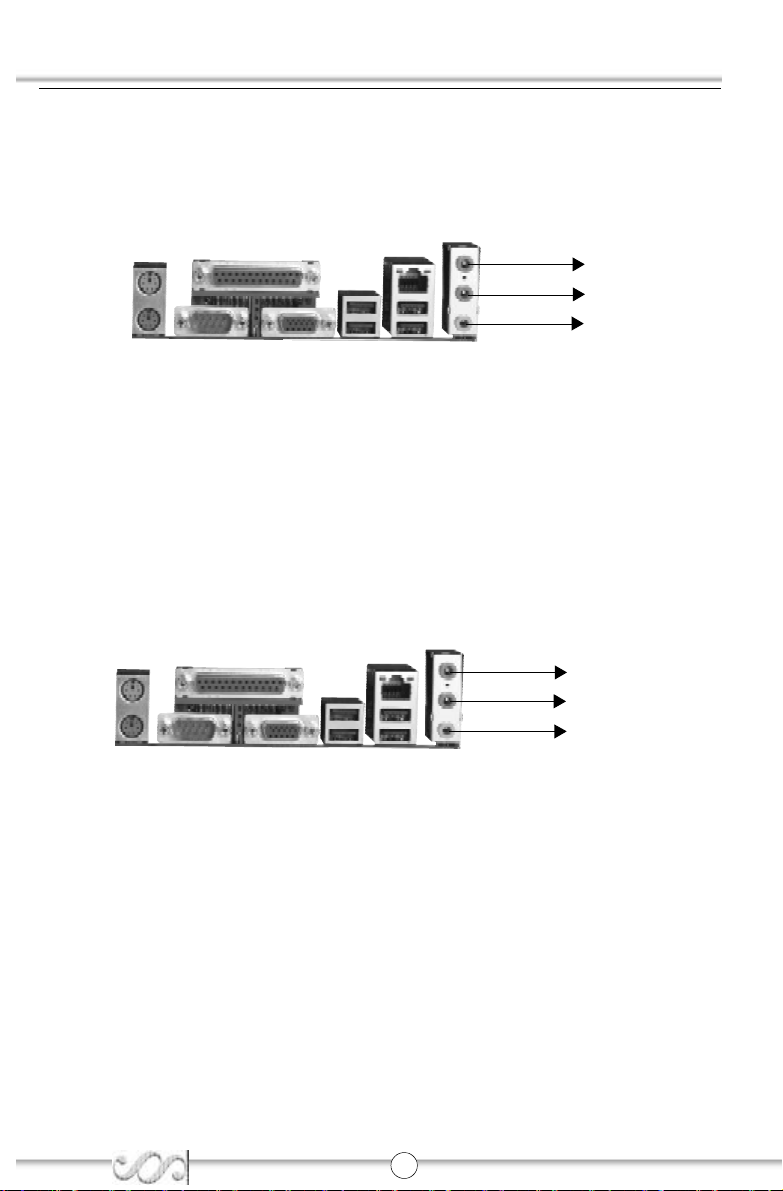
OnboardAudio
AC’972.3SpecificationCompliant
ProvidesonboardLine-inJack,Microphone-inJackandSpeaker-outJack
6-channelOnboardAudio
AC’972.3SpecificationCompliant
ProvidesFrontleft&right,Rearleft&right/Line-inJackandCenter&Woofer/Microphone-
inJack,whichcan be specified bysoftware
AGPInterface And IntegratedGraphics
Providesone standardVGAconnectorand integratedunichromeTMGraphics
AGPslotsupportsAGP2.0including AGP4Xdatatransfers

Chapter1
K7VM400MPro3
Advancedfeatures
PCI2.2SpecificationCompliant
ProvidesTrend ChipAwayVirusOnGuard
SupportsWindows98/2000/ME/XPsoft-off
SupportsKeyboardPasswordPower-on function(optional)
OnboardSATA(with8237 only)
TwoSATAdevicesincludingSATAHDDandCDROM/DVDROMdevices
Supports150Mbpstransferrate.
BIOS
LicensedadvancedAWARD(Phoenix)BIOS,supportsflashROM,plugandplayready
SupportsIDECDROM/USBbootup.
Greenfunction(optional)
SupportsACPI(AdvancedConfigurationandPowerInterface)andODPM(OSDi-
rectedPowerManagement)
SupportsACPIpowerstatus:S0(full-on),S1(poweron suspend),S3(suspend to
RAM),S4(suspend toDisk,dependson OS)and S5(soft-off)
MainExpansion Slotsand Connectors
Slot/Port(Quantity)Description
PCI(3)PCIslots
IDE(2)IDEports
FLOPPY(1)FloppyDriveport
DDR(2)DIMMsocket
USB(6/8)USBconnectors
AGP(1)AGPslot
LAN(1)(option)LANconnector
COM(1)COMconnector
PARALLEL(1)Parallelconnector

InstallationInstructions
K7VM400MPro
4
Chapter2
Installation Instructions
ThissectioncoversExternalConnectorsandJumperSettings.Refer
tothe mainboardlayoutchartforlocationsofall jumpers,external
connectors,slotsand I/Oports.Furthermore,thissection listsall
necessaryconnectorpinassignmentsforyourreference.The par-
ticularstateofthejumpers,connectorsandportsareillustratedinthe
following figures.Beforesetting the jumpersorinserting these
connectors,pleasepayattention tothe direction.

Chapter2
K7VM400MPro
5
ExternalConnectors
PS/2Keyboard/Mouse Connector
PS/2keyboardconnectorisforthe usage ofPS/2keyboard.If using astandardATsize
keyboard,anadaptershouldbeusedtofitthisconnector.PS/2mouseconnectorisforthe
usageofPS/2mouse.
USB1,USB2;USB3,USB4and LAN Connectors(optional)
FourUSB portsareforconnecting USB devices.The RJ-45 connectorisforonboard
LAN.
ParallelPort,SerialPortConnector(COM)and VGAPort
Theparallelportconnectorcanbeconnectedtoaparalleldevicesuchasaprinter.Theserial
portCOM1connectorcanbeconnectedtoaserialportdevicesuchasaserialportmouse.
Youcanenable/disablethemandchoosetheIRQorI/Oaddressin“Integrated Peripherals”
fromAWARDBIOSSETUP.TheVGAconnectorisforoutputtoaVGA-Compatibledevice.
BesuretounplugtheACpowersupplybeforeaddingorremoving
expansion cardsorothersystemperipherals,otherwiseyour
mainboardandexpansioncardsmightbeseriouslydamaged.
MWarning:
USB1USB3
LAN(optional)
USB2USB4
ParallelPort
COM
PS/2Mouseconnector
PS/2Keyboardconnector
VGAPort

InstallationInstructions
K7VM400MPro
6
Line-injack,Microphone-injack and Speaker-outjack
The Line-injack can be connected todevicessuchasacassetteorminidisc playerto
playback orrecord.The Microphone-injack can be connected toamicrophone forvoice
input.TheSpeaker-outjackallowsyoutoconnectspeakersorheadphonesforaudiooutput
fromtheinternalamplifier.
6-ChannelAudio
ThismainboardutilizesALC655 chipproviding 6-channelAudio,whichconsistsofFront
Left,FrontRight,RearLeft,RearRight, CenterandWooferforacompletesurroundsound
effect.When6-Channelaudioisavailable,thefrontLeft&Rightjackcanbeconnectedtothe
Frontspeskers,the Back Left&Rightjack can be connected tothe rearspeakersand the
Center&Wooferjack canbeconnectedtothe centerspeakerand woofer.
MicrophonefunctionisofferedbyF_AUDIOConnectoronthemainboardnow.
Ifset2-ChannelAudiomodeon-6Aor-6ALmainboard,youcanconnecttwospeakersto
theFrontLeft&Rightjack,atthesametimeusetheRearLeft&RightjackasLineinjack,and
usetheCenter&WooferjackasMicrophoneinjack.
Speakerout
Line in
Microphone in
FrontLeft&Right
RearLeft&Right
Center&Woofer

Chapter2
K7VM400MPro
7
HardDisk LEDConnector(HD_LED)
Theconnectorconnectstothecase’sIDEindicatorLEDindicatingtheactivitystatusofIDE
harddisk.The connectorhasan orientation.If one waydoesn’twork,trythe otherway.
ResetSwitch(RESET)
The connectorconnectstothe case’sresetswitch.Press the switchonce,the system
resets.
If you change “Soft-off byPWR-BTTN”fromdefault“Instant-off”
to“Delay4Sec”inthe “POWERMANAGEMENTSETUP”section
ofthe BIOS,the powerswitchshouldbe pressed formorethan
4secondsbeforethe systempowersdown.
ANote:
ATXPowerSupplyConnector&PowerSwitch(POWERSW)
The powerswitch(POWERSW)shouldbe connected toamomentaryswitch.When
powering up yoursystem,firstturnon themechanicalswitchofthe powersupply(ifone
isprovided),then pushoncethe powerswitch.When powering off the system,you
needn’tturnoff the mechanicalswitch,justpushoncethe powerswitch.
POWERSW
1
ATXPowerSupplyConnector
20
1
12V
5VSB
5V
GND
3.3V
GND
5V
GND
PS-OK
3.3V
5V5V
-5V
GND
PS-ON
-12V
3.3V
GND
GND
GND

InstallationInstructions
K7VM400MPro
8
PowerLEDConnector(PWR_LED)
WhenthesystemisinS0status,the LEDison.WhenthesystemisinS1status,theLED
isblink;When the systemisinS3,S4,S5status,the LEDisoff. The connectorhasan
orientation.
FanConnectors(CPUFAN,SYSFAN)
The fan speed ofthesethree fanscan be detected and viewed in“PCHealth”section of
theCMOSSETUP.
SYSFAN
CPUFAN+12V
GND
SENSE
+12V
GND
SENSE
POWER LED
HDD LED
HDD LED(+)
HDD LED(-)
GND
POWER
EMPTY
REVERSE
GND
POWER
PWRLED(+)
RESET
PWRLED(-)
POWER SW
HD LED
POWER
LED
PowerSW
RESET
Reserved

Chapter2
K7VM400MPro
9
USB5,6;USB7,8(with8237 only)
BesidesUSB1,2,3,4onthebackpanel,K7VM400MProseriesofmainboardsalsohave10-
pinheaderson boardwhichmayconnecttofrontpanelUSB cable(optional)toprovide
additionalfourUSBports.
InfraredHeader(IrDA)
Thisconnectorsupportswireless transmitting and receiving device.Beforeusing this
function,configurethe settingsforIRAddress,IRMode and IRIRQfromthe “INTE-
GRATEDPERIPHERALS”sectionoftheCMOSSETUP.
IrDA
1
VCC
IRRX
GND
IRTX
CUT
USB5_6
USB7_8(with8237 only)
1
+5V
GND
GND
+5V
GND
USB+
USB-
CUT
USB+
USB-
1
+5V
GND
GND
+5V
GND
USB+
USB-
CUT
USB+
USB-

InstallationInstructions
K7VM400MPro
10
AudioConnectors(CD_IN,AUX_IN(optional))
CD_INisSonystandardCD audioconnector,itcan be connected toaCD-ROMdrive
through aCD audiocable.AUX_INallowyou toreceivestereo audioinputfromsound
sourcessuchasaTVtuner,orMPEGcard.
CD_INCD RightChannel
GND
CD Left Channel
AUX_IN
(optional)
RightAudioChannel
GND
LeftAudioChannel
AudioInterface(F_AUDIO)(Optional)
The audiointerfaceprovidestwokindsofaudiooutputchoices:the FrontAudioand the
RearAudio.Theirprioritylevelisassequence.When the FrontAudioisavailable,the
RearAudiowill be cutoff. Anonboardamplifierisprovided forthe earphone.When the
FrontAudioisabsent,Pin5andPin6,Pin9 andPin10mustbeshortconnected.
F_AUDIO
(AudioInterface)
Pin
No. Symbol Pin
No. Symbol
1AUD_MIC 2AUD_GND
3AUD_MIC_BIAS
4AUD_VCC
5AUD_FPOUT_R
6AUD_RET_R
7NC 8(Cut away)
9AUD_FPOUT_L
10 AUD_RET_L
2
4
6
8
10
1
3
5
7
9

Chapter2
K7VM400MPro
11
Wake-UpOnInternalModem(WOM)(optional)
Through thisfunction,the systemwhichisinthe suspend orsoft-off statuscan be
waked upbyaring signalreceivedfromthe internalmodem.Whenthisfunctionisused,
be surean internalmodemcardwhichsupportsthisfunction isused.Then connectthis
headertothe relevantconnectoron the modemcard,set“Poweron byRing/LAN”as
Enabledinthe“PowerManagementSetup”sectionoftheCMOSSETUP.Saveandexit,
then bootthe operating systemoncetomakesurethisfunction takeseffect.
OnboardSATA(with8237 only)
The mainboardprovidestwoSerialATAconnectors,SATAisastorage interfacethatis
compliantwithSATA1.0Specification.Withspeed ofup to150Mbps.you can connect
SerialATAcabletoSerialATAharddisk.
SATA1/SATA2
RX-
TX-
GND
GND
GND
RX+
TX+
WOMSignalforwakingup(activelow)
+5Vstandby
GND
1

InstallationInstructions
K7VM400MPro
12
SPDIFOUTConnector(optional)
TheSPDIFoutputallowyourdigitalaudioinputfromdigitalaudiodevices.
SPDIFout
GND
Cutaway
SPDIF
JSPEAK Connector(optional)
SPK_DATA
GND
NC
SPK_VCC
1
1

Chapter2
K7VM400MPro
13
JumperSettings
Jumpersarelocated on the mainboard,the clearCMOSjumperJCC,enablekeyboard
passwordpower-on functionjumperJKBetc.Pin1forall jumpersarelocatedon the side
withathickwhiteline(Pin1→),referringtothemainboard’ssilkscreen.Jumpers
withthree pinswill be shownastorepresentpin1 &pin2 (“1-2”)closed and
torepresentpin2 &pin3 (“2-3”)closed.
JumperSymbolDescription Represent
1-2setpin1and pin2closed
2-3setpin2and pin3closed
closesetthe pinsclosed
open setthe pinsopened
ClearCMOS(CLR_CMOS)
If youwanttoclearCMOS,unplug theACpowersupplyfirst, closeCLR_CMOS(pin2 &
pin3)once,setCLR_CMOSback tothe normalstatuswithpin1&pin2connected,then
poweron the system.
ClearCMOS
Normalstatus
(Unplug the AC
powersupply)
1
3
2
1
3
2

InstallationInstructions
K7VM400MPro
14
Overclocking JumperSetting (JFSB1,JFSB0)(optional)
JumpersJFSB0andJFSB1providesuserswithCPUoverclockingfeature.Thehostbus
speed can be setas200/266/333MHz.The tablebelowisforyourreference.
Whetherornotyoursystemcanbeoverclocked dependsonthecapabilityofyourproces-
sorandmemory.Whetherthe processorisbusratiolocked orunlocked shouldalsobe
taken intoaccount. Forbusratiounlocked processor,thisoverclocking featurecan be
implemented bysetting FSB as200/266/333MHz,meanwhileadjusting the busratio
(multiplier)in“QDIInnovationfeatures”inAWARDBIOSCMOSSetupandmemorry.
Besureyourselection isright. CPUoverspeeding isdangerous!We
will notbe responsibleforanydamagescaused.
MWarning:
CPU 100MHz
133 MHz
166 MHz
JFSB0 OPEN OPEN SHORT
JFSB1 SHORT
OPEN OPEN
JFSB1/JFSB0

Chapter2
K7VM400MPro
15
BIOS-Protection Jumper(BIOS_WP)
TheBIOSofthemainboardisinsidetheFWH.IfthejumperBIOS_WPissetasclosed,the
systemBIOSisprotected frombeing attacked byseriousvirussuchasCIHvirus,you
will be unabletoflashthe BIOStothe mainboardinthisstatus.
Setting thejumperBIOS_WPasopen(default),meanwhiledisablingthe“FlashWritePro-
tect”itemfrom“QDIInnovation features”inAWARD BIOSCMOSSetup,allowsyou to
flashtheBIOStotheFlashROM.
Underspecialconditions,thejumper“BIOS_WP”shouldbesetasOPEN.
EnableFront/BackPanelUSBDeviceWake-upFunction(JUSB1/JUSB2)
(optional)
ThemainboardprovidestheadvancedUSBdevicewake-upfunction.Thesystemcanbe
waked up fromitspowersaving statusincluding ACPIS3byactivating USB device.
Beforeusing thisfunction,setJUSB1/JUSB2withpin1 &pin2 closed.Otherwise,set
JUSB1/JUSB2withpin2&pin3closedfordisabling.
BIOS_WP
FlashWrite
Disabled
FlashWrite
Enabled
JUSB1
JUSB2
Enable
Disable
123123
Enable
Disable
12312 3

InstallationInstructions
K7VM400MPro
16
Enablekeyboardpasswordpower-on function (JKB)(optional)
The mainboardprovidesthe advanced keyboardpasswordpower-on function.Before
usingthisfunction,setJKB withpin1&pin2 closed.Otherwise,setJKBwithpin2 &pin3
closed fordisabling.
Furthermoreinordertoimplementthisfunction,set“POWERONFunction”to“Password”
andenterthekeyboardpower-onpasswordinthe“INTEGRATEDPERIPHERALS”sec-
tion ofthe CMOSSETUP.Saveand exit, then poweroff yoursystem.Inthiscase,the
powerbutton’spower-on function isdisabled.
1.If using thisfunction,5VSB line ofthe powersupplyshouldbe
capableofdelivering enough currentforall the devicescon-
nected tothe keyboardport, ifnot, you will be unabletopower
up the systemusing the keyboard.
2.If yousetJKB withpin2&pin3 closed,set“POWERONFunc-
tion”toBUTTONONLY,don’tsetittoPassword,oryou’ll be
unabletopowerup yoursystembythe keyboardorthe power
button.
3.If you encounterthe aboveproblems,clearCMOSand set
the jumperpin2 and pin3closed todisablethefunction,them
poweron the systembypushing the powerbutton,and set
“poweron Fuction”back to“Button Only”.
4.When the systemisinS5(soft-off)status,the mainboard
suppportskeyboardpasswordpower-on function.
ANote:
JKB
Disable
Enable
123
123

Chapter3
K7VM400MPro
17
Chapter3
BIOSDescription
ThemainboardusesAWARDBIOSSetupprogramthatprovidesa
Setup utilityforuserstomodifythe basicsystemconfiguration.
The information isstored inCMOSRAMsoitretainsthe Setup
information when the poweristurned off. Thischapterprovides
you withthe overviewofthe BIOSSetup.

BIOSDescription
K7VM400MPro
18
AWDFLASH.EXE
Thisisaflashmemorywrite/read utilityused forthe purposeofupgrading yourBIOS
when necessary.Beforedoing so,pleasenote:
Westronglyrecommend you onlyupgradeBIOSwhenencounterproblems.
Beforeupgrading yourBIOS,reviewthedescription belowtoavoidmaking
mistakes,destroying theBIOSand resulting inanon-working system.
When youencounterproblems,forexample,youfind yoursystemdoesnotsupportthe
latestCPUreleased afterourcurrentmainboard,you maythereforeupgradethe BIOS,
pleasedon’tforgettosetBIOS_WPasopen anddisablethe“FlashWriteProtect”itemin
AWARDBIOSCMOSSetupfirst.
Followthe stepsexactlyforasuccessfulupgrade.
1.CreateabootablesystemfloppydiskettebytypingFormatA:/sfromtheDOSprompt
underDOS6.xx orWindows9xenvironment.
2.CopyAWDFLASH.EXE(version>=8.24)fromthe directory\Utilitylocated on QDI
DriverCD toyournewbootablediskette.
3.DownloadtheupdatedBIOSfilefromtheWebsite(http://www.qdigrp.com).Please
be suretodownload the suitableBIOSfileforyourmainboard.
4.Decompress the filedownload,copythe BIOSfile(xx.bin)tothe bootablediskette,
and notethe checksumofthisBIOSwhichislocated inreadmefile.
5.Rebootthe systemfromthe bootablediskettecreated.
6.Then run the AWDFLASHutilityatthe A:\promptasshownbelow:
A:\AWDFLASHxxxx.bin
Followthe instructionthroughthe process.Don’tturnoffpowerorresetthe systemuntil
theBIOSupgradehasbeencompleted.
IfyourequiremoredetailedinformationconcerningAWDFLASHUtility,forexample,the
differentusage ofparameters,pleasetype A:\>AWDFLASH/?
ANote:BecausetheBIOSSoftwarewillbeupdatedconstantly,thefollow-
ingBIOSscreensanddescriptionsareforreferencepurposesonly
and maynotreflectyourBIOSscreensexactly.

Chapter3
K7VM400MPro
19
AWARD BIOSDescription
Entering Setup
Poweron the computer,when the following message brieflyappearsatthe bottomof
the screen during the POST(PowerOnSelfTest),press <Del>keytoenterthe
AWARDBIOSCMOSSetupUtility.
Press <Del>toenterSETUP
When you haveentered,the MainMenu appearson the screen.Usethe arrowkeys to
selectamongtheitemsandpressthe<Enter>keytoacceptorenterthe sub-menu.
MainMenu
StandardCMOSFeatures Setup
The basicCMOSsettingsincluded in“StandardCMOSFeatures”areDate,Time,Hard
Disk DriveTypes,FloppyDisk DriveTypesetc.Usethe arrowkeystohighlightthe item,
thenusethe<PgUp>or<PgDn>keystoselectthe valuedesired ineachitem.
QDIInnovation Features
ThissectiondescribesQDIinnovationEASY technology.
AdvancedBIOSFeatures
Thissection allowsyou toconfigureyoursystemforbasicoperation.You havethe
opportunitytoselectthesystem’sdefaultspeed,boot-upsequence,keyboardoperation,
shadowing and security.
AdvancedChipsetFeatures
The chipsetfeaturessetup isused tochange the valuesofthe chipsetregisters.The
registerscontrolmostofthe systemoptionsinthe computer.
PowerManagementSetup
The powermanagementsetup menu allowsyou toconfiguresystemtomostsaveen-
ergywhileoperating inamannerconsistentwithyourownstyleofcomputeruse.
PnP/PCIConfigurations
Thissection describeshowtoconfigurethe PCIbussystem.Thissection coverssome
verytechnicalitemsanditisrecommendedthatonlyexperiencedusersshouldmakeany
changestothe defaultsetting.

BIOSDescription
K7VM400MPro
20
IntegratedPeripherals
The integrated peripheralssetup allowsusertoconfigurethe onboardIDEcontroller,
floppydisk controller,the printerportand the serialportsetc..
PCHealthStatus
ThePChealthstatusdisplayCPUandcasefanspeed.
LoadFail-SafeDefaults
The BIOSdefaultshavebeen setbythe manufacturerand representsettingswhich
providethe minimumrequirementsforyoursystemtooperate.
LoadOptimizedDefaults
The Optimized Defaultsarecommon and efficient. It isrecommended usersload the
optimized defaultsfirst, then modifythe needed configuration settings.
SetSupervisor/UserPassword
Changes,sets,ordisablespassword.Itallowsyou tolimitaccess tothe systemand the
setup program.When thisfunction isselected,the following message appearsatthe
centerofthe screen toassistyou increating apassword.
ENTERPASSWORD
Type thepassword,up toeightcharacters,and press <Enter>.The passwordtyped now
will clearanypreviouslyentered passwordfromCMOSmemory.You will be asked to
confirmthe password.Type the passwordagainand press <Enter>.You mayalsopress
<Esc>toaborttheselection.
Todisablepassword,justpress <Enter>when you areprompted toenterpassword.A
message will confirmthe passwordbeing disabled.Oncethe passwordisdisabled,the
systemwill bootandyou canenterBIOSSetup freely.
PASSWORD DISABLED
If you haveselected “System”in“SecurityOption”of“BIOSFeaturesSetup”menu,you
will be prompted forthe passwordeverytimethe systemrebootsoranytimeyou tryto
enterBIOSSetup.
Ifyouhaveselected“Setup”at“SecurityOption”from“BIOSFeaturesSetup”menu,youwill
beprompted forthepasswordonlywhenyouenterBIOSSetup.
SupervisorPasswordhashigherprioritythan UserPassword.You can useSupervisor
Passwordwhen booting the systemorentering BIOSSetup tomodifyall settings.Also
youcanuseUserPasswordwhenbootingthesystemorenteringBIOSSetupbutcannot
modifyanysetting ifSupervisorPasswordisenabled.
Save &ExitSetup
Savesvalue changestoCMOSand exitssetup.
ExitWithoutSaving
Abandonsall CMOSvalue changesand exitssetup.
Note:ifyou needdetailedinformation aboutBIOS,please viewthemintheCD.
Other manuals for K7VM400M Pro Series
1
Table of contents
Other QDI Motherboard manuals

QDI
QDI SynactiX 5EP User manual

QDI
QDI Superb 4LE Series User manual

QDI
QDI Pentium P5I430TX/IIB TITANIUM IIB User manual

QDI
QDI CenturieX 1 User manual

QDI
QDI Advance 6T User manual

QDI
QDI Advance 5 User manual

QDI
QDI P6I440BX/B1S User manual

QDI
QDI PlatiniX 4X User manual

QDI
QDI KinetiZ 7A User manual

QDI
QDI Advance 5/133E User manual

QDI
QDI Advance 10TM User manual

QDI
QDI P2S User manual

QDI
QDI PlatiniX 1D Series User manual

QDI
QDI P5I915PL User manual

QDI
QDI XT4500 Series User manual

QDI
QDI LEGEND-V User manual

QDI
QDI P4I865G User manual

QDI
QDI Advance 12 Series User manual

QDI
QDI PlatiniX 2E/333 User manual

QDI
QDI PlatiniX P8/333 Series User manual