QDI PlatiniX 2D User manual

Declaration of Conformity
QUANTUM DESIGNS(HK) LTD.
20th Floor, Devon Hou e, Taikoo Place, 979 King Road,
Quarry Bay, Hong Kong
declares that the product
Mainboard
PlatiniX 2D
is in conformity with
(reference to the specification under which conformity is declared in
accordance with 89/336 EEC-EMC Directive
!"EN 55022 Limits and methods of measurements of radio disturbance
characteristics of information technology equipment
!"EN 50081-1 Generic emission standard art 1:
Residential, commercial and light industry
!"EN 50082-1 Generic immunity standard art 1:
Residential, commercial and light industry
European Representative:
QDI COM UTER( UK ) LTD. QDI COM UTER( SCANDINAVIA )A/S
QDI SYSTEM HANDEL GMBH QDI EURO E B.V
QDI COM UTER( FRANCE ) SARL QDI COM UTER HANDELS GMBH
LEGEND QDI S AIN S.L. QDI COM UTER( SWEDEN )AB
Signature : lace / Date : HONG KONG/2001
rinted Name : Xu Wenge osition/ Title : Assistant resident

Declaration of Conformity
Trade Name: QDI Computer ( U. S . A. Inc.
Model Name: PlatiniX 2D
Responsible Party: QDI Computer ( U. S. A. Inc.
Address: 41456 Christy Street
Fremont, CA 94538
Telephone: (510 668-4933
Facsimile: (510 668-4966
Equipment Classification: FCC Class B Subassembly
Type of Product: Motherboard
Manufacturer:Quantum Designs (HK) Inc.
Address: 20th Floor, Devon House, Taikoo Place
979 Kings Road, Quarry Bay, HONG
KONG
Supplementary Information:
This device complies with Part 15 of the FCC Rules. peration is subject
to the following two conditions : (1) this device may not cause harmful
interference, and (2) this device must accept any interference received,
including interference that may cause undesired operation.
Tested to comply with FCC standards.
Signature : Date : 2001

II
CONTENTSCONTENTS
CONTENTSCONTENTS
CONTENTS
1. Introduction ............................................... 1
Overview ........................................................................ 1
Key Features .................................................................. 1
2. In tallation In truction ............................. 4
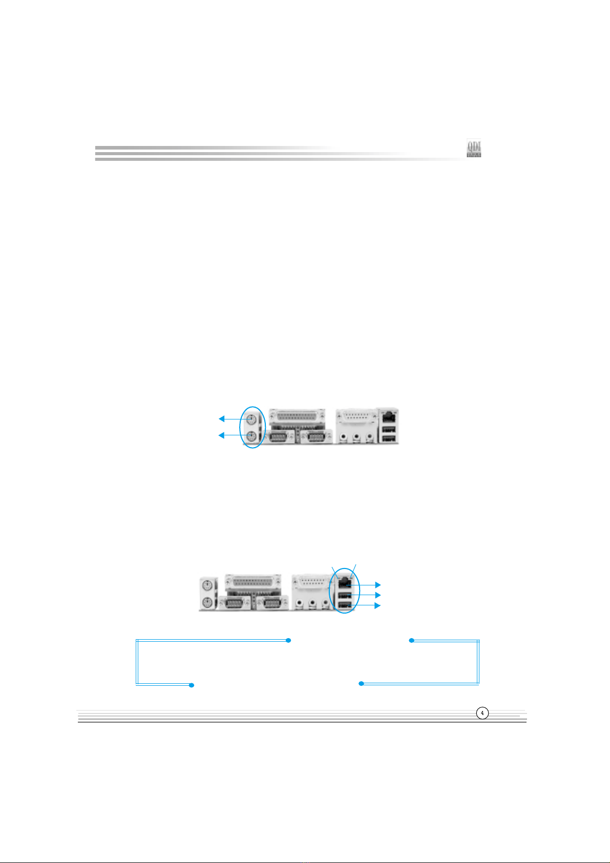
External Connectors .............................................. 4
PS/2 Keyboard /Mouse Connector ................................... 4
USB1, USB2 and AN Connectors ................................... 4
Parallel Port, Serial Port Connectors................................... 5
ine-in jack, Mic-in jack, Speaker-out jack and
MIDI/Joystick Connector........................... .... ......................5
Chassis Security Switch(CHSSEC).....................................5
ATX 12V Power Supply Connectors & Power Switch ...... 6
Hard Disk ED Connector ( HD_ ED ) ............................... 6
Reset Switch ( RESET ) ................................................... 6
Speaker Connector ( SPEAKER ) ..................................... 7
Power ED Connector( PWR_ ED ) ................................. 7
Green ED Connector( GREEN_ ED ) .............................. 7
ACPI ED Connector( ACPI_ ED ) .................................... 7
Hardware Green Connector ( S EEP SW ) ...................... 7
Key ock Connector( KEY K ) ........................................ 7
USB3, 4 Connector .......................................................... 8
Infrared Header ( IrDA ) ................................................... 8
Sound Connector( PC-PCI ) .............................................. 8
Fan Connectors( CPUFAN , CHSFAN, PWRFAN ) .............. 9
Intruder Detect Switch( JINTR ) ........................................ 9
Wake-Up On AN ( WO ) ................................................10
Wake-Up On Internal Modem ( WOM )................................10
Audio Connectors ( AUXIN, CD_IN, MODEM ).....................11
4-pin SMBus Connector( SMBUS ).....................................11
Diagnosis ED ....................................................................12
Communication and Networking Riser Slot( CNR )..............12
Audio Interface...................................................................13
Main Expqnsion slot and Connectors.........................13
Jumper Settings......................................... ..................14
BIOS-Protection Jumper( JAV )................. .........................14
Overclocking Jumper Setting( JFS0,JFS1 ).........................15

II
CONTENTSCONTENTS
CONTENTSCONTENTS
CONTENTS
Clear CMOS(JCC)..................................................16
CPU Core Voltage Setting( JVID0~4 ).....................16
Enable Front/Back Panel USB Device
Wake-up Function( JUSB, JFUSB )........................18
Enable/Disable onboard Audio( JSD )....................18
Enable keyboard password power-on
function(JKB).........................................................19
3. BIOS De cription.............................20
Utility Support.....................................................20
AWDF ASH.EXE ....................................................20
AWARD IOS Description...............................21
Entering Setup .......................................................21
oad Optimized Defaults .......................................21
Standard CMOS Features Setup............................21
CPU SpeedEasyII Setup..........................................25
Advanced BIOS Features Setup............................26
Advanced Chipset Features Setup........................28
Power Management Setup.....................................30
PnP/PCI Configurations Setup.................................33
Integrated Peripherals.............................................34
PC Health Status.....................................................37
Password Setting...................................................39
Boot with BIOS defaults.........................................39
Appendix...........................................................40
DI Driver CD......................................................40
ManageEasy........................................................41
BIOS-ProtectEasy...............................................41
Norton AntiVirus..................................................41
LogoEasyII...........................................................42
BootEasy..............................................................43
RecoveryEasy......................................................46
StepEasyII............................................................54
SpeedEasyII........................................................56
Platinix2D(French).............................................58
Platinix2D(Spanish)............................................62
Layout

Manual for latiniX 2D series
Chapter 1
Chapter 1
Introduction
Overview
PlatiniX 2D series of mainboards utilize Intel® 845DDR chipset consisting of two compo-
nents: the Intel® i845DDR Memory Controller Hub(Brookdale MCH) and the 82801BA I/O
Controller Hub2(ICH2), providing a fully compatible, high performance and cost-effective
PC/ATX platform. The new integrated technologies, together with AGP 4X support, AC97
audio, integrated AN(optional), 4 USB ports, and ATA66/100/33, give customers an
advanced, multimedia solution at reasonable price. It provides 400MHz host bus speed to
support Intel®
Pentium 4 socket 478 processors and the largest DDR memory capacity is
up to 2GB. It also provides advanced features such as Wake up by USB devices, Wake-
on- AN, Wake-on-Modem, ACPI and Keyboard Password Power-on functions. Suspend
to RAM, the optimal implementation of the Advanced Configuration and Power Interface
(ACPI) specification, makes the PCs power consumption drop to the lowest possible level
and enable quick wakeup. BootEasy, QDI innovation, lets the PC boot freely and rapidly.
StepEasyII, our new innovation is also supplied to enable you to adjust CPU frequency
step by step easily to utilize CPUs potential ability.
Key Features
Form factor
#"ATX form factor of 305mm x 224mm
Microprocessor
#"Supports Intel® Pentium 4 (Willamette) socket 478 processors at 1.4/1.5/1.6/1.7/1.8/1.9
2.0GHz and above
#"Supports Intel® Pentium 4 (Northwood) socket 478 processors at 2.0/2.2GHz and
above
#"Supports 400MHz host bus speed
System memory
#"Provides two 184-pin DDR SDRAM interfaces
#"Supports DDR200/DDR266 SDRAM
#"Supports 64/128/256/512Mb technology up to 2GB
Onboard IDE
#"Supports Independent timing of up to 4 drives
#"Supports Ultra ATA 33/66/100, PIO mode
#"Two fast IDE interfaces supporting four IDE devices including IDE hard disks and CD
ROM drives

Manual for latiniX 2D series
Introduction
Onboard LAN (available on PlatiniX 2D-L/-AL, PlatiniX 2DI-L/-AL)
#"10/100 Mbit/sec Ethernet support
#"10/100M AN interface built-in on board
4 US
#"USB 1.1 compliant
#"Supports wake-up from S1 (power on suspend), S3(depends on device)
Onboard I/O
#"One floppy port supporting up to two 3.5″ or 5.25″ floppy drives with 360K/720K/1.2M/
1.44M/2.88M format
#"Two high speed 16550 compatible UART (COM1/COM2/COM3/COM4 selective) with
16 byte send/receive FIFO
#"One parallel port supports SPP/EPP/ECP mode
#"Infrared interface
#"All I/O ports can be enabled/disabled in the BIOS setup
Onboard Audio(available on PlatiniX 2D-A/-AL, PlatiniX 2DI-A/-AL)
#"AC97 2.1 Specification Compliant
#"16bit stereo codec
#"Multiple stereo input mixer
#"Mono and stereo volume control
#"Provides onboard ine-in Jack, Microphone-in Jack, Speaker-out Jack with onboard
amplifier and MIDI/Joystick Connector
AGP Interface
#"AGP Connector supports AGP 2.0 including AGP 4x data transfers
Advanced features
#"PCI 2.2 Specification Compliant
#"Provides Trend ChipAwayVirus On Guard
#"Supports Windows 98/2000/ME soft-off
#"Supports Wake-on- AN and Wake-on-Modem
#"Supports Keyboard Password Power-on function
#"Supports system monitoring(monitors CPU and system temperatures, system
voltages, fan speed)
#"Providing QDI innovations: RecoveryEasy, BIOS-ProtectEasy, ogoEasyII,
ManageEasy(optional), BootEasy, StepEasyII, SpeedEasyII.

Manual for latiniX 2D series
Chapter 1
IOS
#"icensed advanced AWARD(Phoenix) BIOS, supports flash ROM, plug and play ready
#"Supports IDE CDROM/SCSI boot up
Green function
#"Supports ACPI (Advanced Configuration and Power Interface) and ODPM (OS
Directed Power Management)
#"Supports ACPI power status: S0 (full-on), S1 (power on suspend), S3 (suspend
to RAM), S4(suspend to Disk,depends on OS) and S5 (soft-off)
New Feature
#"CPU,AGP,DDR Voltage adjusting function
Adjusting CPU core voltage in BIOS to improve system stability and overclocking ability.
Adjusting AGP voltage in BIOS to improve system stability and overclock ability.
Adjusting DDR voltage in BIOS to improve system stability and overclock ability.
#" Diagnosis LED
The mainboard provides Diagnosis ED function to indicate CPU, chipset, memory,
PCI device, clockgen and Video status during system booting up.This function may
make maintance of your computer more convenient and simple.During POST, if CPU is
burned out or the BIOS chip is damaged or CPU is absent, ED1 will blink at a frequency
of 1Hz, when the POST comes to CPU checking and chipset initializing, memory testing,
PCI detecting, clockgen initializing and Video initializing, the EDs will light up in turn.
When the POST finishes all the 5 EDs will turn off. Otherwise the coresponding ED
will remain light up to indicate a problem occurs.
#" Po er supply flexibility
Users are strongly recommanded to use an ATX12V power supply. However, the
PlatiniX 2D mainboard can also work with a legacy ATX power supply as long as its
+12V rail can deliver enough current(at least 8 Amperes).
NOTE: System stability with an ATX power supply is not guaranteed here and we are
not responsible for any damage caused.

T-- This page is intentionally left blank --his

Manual for latiniX 2D series
Chapter 2
PS/2 Mouse
Connector
PS/2 Keyboard
Connector
@
Chapter 2
Installation Instructions
This section covers External Connectors and Jumper Settings. Refer to the mainboard
layout chart for locations of all jumpers, external connectors, slots and I/O ports.
Furthermore, this section lists all necessary connector pin assignments for your refer-
ence. The particular state of the jumpers, connectors and ports are illustrated in the
following figures. Before setting the jumpers or inserting these connectors, please
pay attention to the direction.
External Connectors
PS/2 Keyboard/Mou e Connector
PS/2 keyboard connector is for the usage of PS/2 keyboard. If using a standard AT size
keyboard, an adapter should be used to fit this connector. PS/2 mouse connector is for
the usage of PS/2 mouse.
USB1, USB2 and LAN Connector
( AN connector is only available on PlatiniX 2D- /-A , PlatiniX 2DI- /-A )
Two USB ports are for connecting USB devices. The RJ-45 connector is for onboard AN.
Be sure to unplug the AC po er supply before adding or removing expansion
cards or other system peripherals, other ise your mainboard and expansion
cards might be seriously damaged.
USB1
USB2
LAN(optional)
L NK ACT VE

Manual for latiniX 2D series
Parallel Port, Serial Port Connector (UART1, UART2)
The parallel port connector can be connected to a parallel device such as a printer.
The serial port UART1,2 connectors can be connected to a serial port device such as a
serial port mouse. You can enable/disable them and choose the IRQ or I/O address in
Integrated Peripherals from AWARD CMOS SETUP.
Line-in jack, Microphone-in jack, Speaker-out jack and MIDI/Joy tick
Connector (available on PlatiniX 2D-A/-AL, PlatiniX 2DI-A/-AL)
The ine-in jack can be connected to devices such as a cassette player or minidisc player to
playback or record. The Microphone-in jack can be connected to a microphone for voice
input. The Speaker-out jack allows you to connect speakers or headphones for audio
output from the internal amplifier.The MIDI/Joystick connector allows you to connect a
game joystick or a MIDI device.
Installation Instructions
MIDI/Joystick
Speaker out Line in Microphone in
Parallel Port
UART1 UART2
Cha i Security Switch (CHSSEC)
The connector connects to the chassis security switch on the case. The system can
detect the chassis intrusion through the status of this connector. If the connector has
been closed once, the system will record the status and indicate the chassis has been
opened. You can monitor or check this information from QDI ManageEasy(optional) soft-
ware.
GND
ndicate signal
CHSSEC

Manual for latiniX 2D series
ATX12V Power Supply Connector & Power Switch (POWER SW)
The PlatiniX 2D series mainboards prefer an ATX12V power supply. Be sure to connect the
ATX 12V power supply plugs to the connectors in their proper orientation. The difference
between ATX12V power supply and ATX power supply is that ATX12V power supply
provides two additional power connectors: AUX power connector and +12V power
connector.However,the PlatiniX 2D series mainboard provide an unique design especially
for those who still use legacy ATX power supply(without AUX and +12V connector) as
long as their ATX power supplies can provide enough current on +12V rail(at least 8
Amperes). System stability with an ATX power supply is not guaranteed and we are not
responsible for any damage caused.
The power switch (POWER SW) should be connected to a momentary switch. When
powering up your system, first turn on the mechanical switch of the power supply (if one
is provided), then push once the power switch. When powering off the system, you
neednt turn off the mechanical switch, just Push once* the power switch.
Note: * If you change soft-off by PWR-BTTN from default Instant-off to Delay
4 Sec in the POWER MANAGEMENT SETUP section of the CMOS SETUP, the
po er button should be pressed for more than 4 seconds before the system
po ers do n.
Hard Di k LED Connector (HD_LED)
The connector connects to the cases IDE indicator ED indicating the activity status of
IDE hard disk. The connector has an orientation. If one way doesnt work, try the other
way.
Re et Switch (RESET)
The connector connects to the cases reset switch. Press the switch once, the system
resets.
Chapter 2
POWER
SW
GND
GND
12V
12V
+12V Power Supply Connector
ATX Power Supply Connector
5V5V -5V
GND GND PS-ON -12V 3.3V GND
12V 5VSB 5V GND
3.3V GND 5V GND PS-OK 3.3V
GND
AUX Power Supply Connector
GND
3.3V 3.3V GND GND
5V

Manual for latiniX 2D series
Speaker Connector (SPEAKER)
The connector can be connected to the speaker on the case.
Power LED Connector (PWR_LED)
When the system is in S0 status, the ED is on. When the system is in S1 status, the
ED is blink; When the system is in S3,S4, S5 status, the ED is off. The connector has
an orientation.
GREEN LED Connector (GREEN_LED)
When the system is in S0,S1,S4 ,S5 status, the ED is off,When the system is in S3
status, the ED is on.
ACPI LED Connector (ACPI_LED)
The ACPI ED is a dual-color light with three pins. Pin1and Pin2 drive different color
lights. If Pin1 drives the orange light , then, Pin2 drives the green light, the following
status will come out. When the system is in S0 status, the ED is green on. When the
system is in S1 status, the ED is green blink. When the system is in S3 status, the
ED is orange on. When the system is in S4, S5 status, the ED is off.
Hardware Green Connector (SLEEP SW)
Push once the switch connected to this header, the system enters suspend mode.
Key Lock Connector (KEYLK)
The connector can be connected to the keyboard lock switch on the case for locking
the keyboard.
SPEAKER RESET GREEN_LED KEYLK
PWR_LED
ACP _LED
HD_LED
SPEAKER RESET GREEN_LEDKEYLK
ACP _LED SLEEP
SW PWR_LED
HDD LED(+) HDD LED(-)
ORANGE(-)
GREEN(-)
LED+
POWER
GND
EMPTY
EMPTY
SLEEP
GND
LED+
LED-
LED- KEYLOCK
GND
LED-
LED-
LED+
EMPTY
GND
RESET
SPKDATA
NC
GND
VCC
POWER
SW
POWER
SW
SLEEP
SW
Installation Instructions

Manual for latiniX 2D series
USB3,4 Connector
Besides USB1,2 on the back panel, PlatiniX 2D series of mainboards also have a 10-pin
header on board which may connect to front panel USB cable( optional ) to provide addi-
tional two USB ports.
Infrared Header (IrDA)
This connector supports wireless transmitting and receiving device. Before using this
function, configure the settings for IR Address, IR Mode and IR IRQ from the INTE-
GRATED PERIPHERA S section of the CMOS SETUP.
Sound Connector (PC-PCI)
This connector provides a bridge between the mainboard and PCI sound card to de-
liver sound compatibility under DOS real-mode environment.
PC-PCI
+5V
D3+
D3-
GND
GND
GND
GND
D4+
D4-
+5V
USB3,4
VCC
RRX
GND
RTX
NC
IrDA
Chapter 2
1
GND
SERIAL INTERRUPT REQUEST
PC-PCI DMA REQUEST
PC-PCI DMA ACKNOWLEDGE
GND
NC

Manual for latiniX 2D series
Fan Connector (PWRFAN, CPUFAN, CHSFAN)
The fan speed of these three fans can be detected and viewed in PC Health section
of the CMOS SETUP. These three fans will be automatically turned off after the sys-
tem enters suspend mode.
Intruder Detect Switch(JINTR)(Re erved)
The connector connects to the chassis security switch on the case. The system can
detect the chassis intrusion through the status of this connector. If the connector has
been closed once, the system will send a message over the network to alert the net-
work manager through the on board AN controller within ICH2.
C SFAN
CPUFAN
PWRFAN
SENSE
+12V
GND
GND
SENSE
SENSE
+12V
GND
GND
ndicate signal
JINTR
Installation Instructions
+12V

Manual for latiniX 2D series
Wake-Up On Internal Modem (WOM)
Through this function, the system which is in the suspend or soft-off status can be
waked up by a ring signal received from the internal modem. When this function is
used, be sure an internal modem card which supports this function is used. Then
connect this header to the relevant connector on the modem card, set Wake-Up by
Ring/ AN as Enabled in the Power Management Setup section of the CMOS SETUP.
Save and exit, then boot the operating system once to make sure this function takes
effect.
Wake-Up On LAN (WOL)
Through the Wake-Up On AN function, a wake event occurring from the network can
wake up the system. If this function is to be used, please be sure an ATX12V power
supply of which 5VSB line is capable of delivering current at least720mA, and a AN
adapter which supports this function is used. Then connect this header to the relevant
connector on the AN adapter, set Wake-Up by Ring/ AN as Enabled in the POWER
MANAGEMENT SETUP section of the CMOS SETUP. Save and exit, then boot the operat-
ing system once to make sure this function takes effect.
+5V standby
GND
Signal for waking up (active
high)
WOL
+5V standby
GND
Signal for waking up (active low)
WOM
Chapter 2

Manual for latiniX 2D series
Audio Connector (CD_IN, MODEM, AUXIN)
(Available on PlatiniX 2D-A/-AL, PlatiniX 2DI-A/-AL)
CD_IN is a Sony standard CD audio connector, it can be connected to a CD-ROM
drive through a CD audio cable. The MODEM connector allows the onboard audio to
interface with a voice modem card with a similar connector. It allows connecting the
mono_in (such as a phone) or mono_out (such as a speaker) between the onboard
audio and the voice modem card. AUXIN allows you to receive stereo audio input from
sound sources such as a TV tuner,or MPEG card.
4-pin SMBu Connector(SMBUS)
This connector allows you to connect SMBus devices. SMBus devices communicate
through the SMBus with a SMBus host and/or other SMBus devices. The SMBus or
System Management Bus is a specific implementation of I2C bus, which is a multi-
master bus, that is, multiple devices can be connected to the same bus and each one
can act as a master by initiating data transfer.
Installation Instructions
Phone- n (from Modem)
CD_ N
Common
CD Right Channel
CD Left Channel
AUX N
Left AudioChannel
Right Audio Channel
GND
GND
Mono-Out (to Modem)
MODEM
SMBDATA
SMBCLK
5VSB
GND
SMBUS

Manual for latiniX 2D series
Communication and Networking Ri er Slot(CNR)
The mainboard provides Communication and Networking Riser(CNR) interface which can
support audio and/or modem functions . Furthermore, it provides a AN interface for network-
ing functions. What its superiority compared with AMR is being able to support plug-and-play
function. Mechanically the CNR shares a PCI slot, thus if a CNR card is not used,users can an
additional PCI slot which shares the same position on back panel with CNR.
By using an audio codec, the AC97 digital link on CNR provides for cost-effective, high-
quality, integrated audio on the platform. AC97 digital link also allows several external
codecs to be connected to the ICH2. The digital link can be expanded to support two or three
audio codecs for up to 6 channels of PCM audio output (full AC-3 decode) or a combination
of an audio and modem codec.
Chapter 2
LED1
LED2LED4
LED5
LED3
Diagno i LED
During the POST ,the ED1~ ED5 representing POST steps will light up in turn, please
refer to the following table to learn the POST status:
CNR Slot
ED1 ED2 ED3 ED4 ED5 status
blink off off off off CPU damaged , BIOS chip absent or damaged
on off off off off system detect CPU and initialize chipset
off on off off off system detect memory
off off on off off system initialize PCI
off off off on off system initialize clockgen
off off off off on system detect Video and invokeVideoBIOS

Manual for latiniX 2D series
Audio Interface-BLSPK(Re erved)
The audio interface provides three kinds of audio output choices: the FrontAudio, the
RearAudio and the ActiveAudio. Their priority level is as sequence. When the
FrontAudio is available, the RearAudio and the ActiveAudio( in-case speakers ) will
be cut off. When the RearAudio is available, the ActiveAudio will be cut off. An onboard
amplifier is provided for the earphone. When the FrontAudio is absent, Pin11 and Pin12,
Pin13 and Pin14 must be short connected.
Pin
No.
Symbol Pin
No.
Symbol
1 Active LINE Out(R) 2 Active LINE Out(L)
3 GND (ALO) 4 GND (ALO)
GND(+12) 6 GND(+12)
7 +12V(1A) 8 (Cut away )
9 MIC 10 GND ( MIC )
11 Front LINE Out ( R ) 12 LINE Next( R )
13 Front LINE Out( L ) 14 LINE Next( L )
1 GND (FLO) 16 (Cut awa y )
BLSPK
(Audio Interface)
Installation Instructions
Main Expansion Slots and Connectors
FrontLineOutR
FrontLineOutL
LineNextR
LineNextL
GND
Front Audio jack
Speaker Out
Line in
Microphone in
Speaker
Earphone
4 6 810121416
2
1 3579111315
Slot/Port ( Quantity ) Description
IDE( 2 ) IDE ports
F OPPY( 1 ) Floppy drive port
DDR( 2 ) DDR SDRAM slots
USB( 4 ) USB connectors
AGP( 1 ) AGP slot
IrDA( 1 ) IrDA connector
CNR(1) CNR slot
PCI( 5+1( optional )) PCI slots
ISA( 1 )( optional ) ISA slot
AN( 1 )( optional ) AN connector
MIDI/Joystick( optional ) MIDI/Joystick connector

Manual for latiniX 2D series
BIOS-Protection Jumper (JAV)
The BIOS of the mainboard is inside the FWH. If the jumper JAV is set as closed, the
system BIOS is protected from being attacked by serious virus such as CIH virus,you will
be unable to flash the BIOS to the mainboard. However in this status .
Setting the jumper JAV as open(default), meanwhile disabling the Flash Write Protect item
from Advanced BIOS Features in AWARD BIOS CMOS Setup, allows you to flash the
BIOS to the Flash ROM.
The DMI (Desktop Management Interface) system information such as the CPU type/
speed, memory size, and expansion cards will be detected by the onboard BIOS and
stored in the flash ROM. Whenever the system hardware configuration is changed, DMI
information will be updated automatically. However, setting jumper JAV as closed makes
flashing BIOS and updating DMI information impossible. Therefore, set JAV as open
when changing the system hardware configuration, or the error message Unknown
Flash Type will be displayed on the screen, and DMI information may not be updated.
Under special conditions, the jumper JAV should be set as OPEN. For further details, refer
to the BootEasy part of appendix.
Chapter 2
Flash Write
Disabled
Flash Write
Enabled
(default)
JAV
JAV
Jumper Settings
Jumpers are located on the mainboard, the yare, clear CMOS jumper JCC, enable keyboard
password power-on function jumper JKB, and enable/disable onboard audio jumper JSD
etc. Pin 1 for all jumpers are located on the side with a thick white line (Pin1→ ),
referring to the mainboards silkscreen. Jumpers with three pins will be shown as
to represent pin1 & pin2 (1-2) closed and to represent pin2 & pin3 (2-3) closed.
Jumper Symbol Description Represent
set pin1 and pin2 closed
set pin2 and pin3 closed
close set the pins closed
open set the pins opened

Manual for latiniX 2D series
1-2: pin1 & pin2 closed
2-3: pin2 & pin3 closed
Installation Instructions
JFS1
1
2
3
JFS0
1
2
3
Overclocking Jumper Setting (JFS0,JFS1)(optional)
Jumpers JFS0 and JFS1 provides users with CPU overclocking feature. The host bus
speed can be set as 66x4/100x4/133x4/200x4MHz or AUTO. If CPU FSB(front side bus)
is set as auto, the system detects the CPU FSB automatically. The table below is for your
reference.
Whether or not your system can be overclocked depends on your processors and memorys
capability. Whether the processor is bus ratio locked or unlocked should also be taken into
account. For bus ratio unlocked processor, this overclocking feature can be implemented
by setting FSB as 66x4/100x4/133x4/200x4MHz, meanwhile adjusting the bus ratio (mul-
tiplier) in CPU SpeedEasyII Setup in AWARD BIOS CMOS Setup and memorry.
You can also adjust the CPU frequency by running StepEasyII. We do not guarantee the
stability of the overclocking system.
Warning: Be sure your selection is right. CPU over speeding is dangerous! We
ill not be responsible for any damages caused.
133x4MHz
66x4MHz 200x4MHz
(default)
CPU FSB 100x4MHz
AUTO
OPEN
(default)
OPEN
2-3
2-32-3
1-21-2
1-2
2-3JFS0
JFS1
OPEN
This manual suits for next models
4
Table of contents
Other QDI Motherboard manuals

QDI
QDI BrillianX 8V User manual

QDI
QDI PlatiniX 1 User manual

QDI
QDI P6I440BX/B1S User manual

QDI
QDI J6A User manual

QDI
QDI P6I440LX/DP User manual

QDI
QDI Advance 6T User manual

QDI
QDI Advance 10TM User manual

QDI
QDI BrillianX 1S/2000 User manual

QDI
QDI PlatiniX 7B User manual

QDI
QDI K7VM400M Pro Series User manual

QDI
QDI P6I440LX/L6 User manual

QDI
QDI X8800 Series User manual

QDI
QDI CenturieX 1 User manual

QDI
QDI Advance 10T Series User manual

QDI
QDI P6I440BX User manual

QDI
QDI P5MVP3/A3 User manual

QDI
QDI P4I865G User manual

QDI
QDI K8N4 Series User manual

QDI
QDI PlatiniX 4N Series User manual

QDI
QDI K8V800 User manual