QDI Superb 3L User manual

Declaration of conformity
QUANTUMDESIGNS(HK)LTD.
20th Floor, Devon House, TaiKoo Place 979 King’s Road,
Quarry Bay, Hong Kong
declares that the product
Mainboard
Superb 3L
is in conformity with
(reference to the specification under which conformity is declared in
accordance with 89/336 EEC-EMC Directive)
þ EN 55022 Limits and methods of measurements of radio disturbance
characteristics of information technology equipment
þ EN 50081-1 Generic emission standard Part 1:
Residential, commercial and light industry
þ EN 50082-1 Generic immunity standard Part 1:
Residential, commercial and light industry
European Representative:
QDICOMPUTER(UK)LTD QDI COMPUTER ( SCANDINAVIA ) A/S
QDISYSTEMHANDELGMBH QDICOMPUTER(NETHERLANDS)B.V.
QDICOMPUTER(FRANCE)SARL QDICOMPUTERHANDELSGMBH
QDICOMPUTER(ESPANA)S.A. QDICOMPUTER(SWEDEN)AB
Signature : Place / Date : HONG KONG/2000
Printed Name : Lv Yan Position/ Title : Assistant President

Declaration of conformity
Trade Name: QDI Computer ( U. S . A. ) Inc.
Model Name: Superb 3L
Responsible Party: QDI Computer ( U. S. A.) Inc.
Address: 41456 Christy Street
Fremont, CA 94538
Telephone: (510) 668-4933
Facsimile: (510) 668-4966
Equipment Classification: FCC Class B Subassembly
Type of Product: Mainboard
Manufacturer:Quantum Designs (HK) Inc.
Address: 20th Floor, Devon House, TaiKoo Place
979 King’s Road, Quarry Bay, HONG
KONG
Supplementary Information:
This device complies with Part 15 of the FCC Rules. Operation is subject to
the following two conditions : (1) this device may not cause harmful interfer-
ence, and (2) this device must accept any interference received, including
interference that may cause undesired operation.
Signature : Date : 2000

I
CONTENTS
SpeedEasyQuickSetup(English)......................................................... 1
SpeedEasy ............................................... 3
Facilitédevitesse Initialisation(Francais) ............................................. 5
1. Introduction................................................................. 9
Overview............................................................................................ 9
KeyFeatures ...................................................................................... 9
Introduction toNew Features ............................................................ 12
I
2. Installation Instructions .............................................15
External Connectors ............................................................... 15
PS/2Keyboard&PS/2MouseConnector........................................... 15
USB1& USB2................................................................................... 15
ParallelPortConnector,SerialPortConnector
MonitorOutputconnector .................................................................. 15
UART2 .............................................................................................. 16
USB3,USB4 ...................................................................................... 16
Line-injack,Microphone-injack,Speaker-outjackandMIDI/Joystick
connector ......................................................................................... 16
ATX Power Supply Connector & Power Switch ................................. 17
HardDiskLEDConnector(HD_LED) .................................................. 17
ResetSwitch(RESET)....................................................................... 17
SpeakerConnector(SPEAKER)......................................................... 17
PowerLEDConnector(PWR_LED) ..................................................... 17
ACPILEDConnector(ACPI_LED) ........................................................ 18
Green LEDConnector(GREEN_LED) ................................................ 18
HardwareGreenConnector(SLEEP)................................................. 18
InfraredHeader (IrDA)....................................................................... 18
Fan Connector(CPUFAN,BAKFAN,CPUFAN) ................................... 19
Wake-UpOnLAN(WOL) ................................................................... 19
Wake-UpOnInternalModem(WOM) .................................................. 20
Audio/ModemRiserInterfaceConnector(AMR).................................. 20
InternalAudioConnector(CDLIN,MODEM)......................................... 21
BLSpeakerConnector(BLSPK) ........................................................ 21

CONTENTS
ExpansionSlots &I/O Portsdescription ................................................. 21
OverclockingJumperSetting(JFSB1,JFSB2) .......................................... 22
ClearCMOS(JCC) .................................................................................. 23
Enable Keyboard password power-on function(JKB)............................23
BIOS-ProtectEasyJumper(JAV)............................................................. 24
Memory Configuration................................................................. 24
3.BIOS Description ..................................................................25
UtilitySupport .............................................................................. 25
AWDFLASH.EXE ................................................................................... 25
AWARD BIOS Description ........................................................... 27
EnteringSetup....................................................................................... 27
LoadSetup Defaults............................................................................ 27
StandardCMOSSetup ......................................................................... 27
SpeedEasyCPUSetup ........................................................................ 30
AdvanceBIOS FeaturesSetup ............................................................ 31
AdvanceChipsetFeatures Setup ........................................................ 33
IntegratedPeripherals.......................................................................... 36
PowerManagementSetup................................................................... 39
PNP/PCIConfigurationSetup ................................................................ 41
PCHealthStatus.................................................................................. 42
Password Setting.................................................................................. 43
Appendix A QDI Driver CD 2000 ............................................ 44
Appendix B Boot Logo .................................................... 46
RecoveryEasy....................................................................47
Introducton ............................................................................................ 47
OperationProcess ................................................................................ 47
FAQ ...................................................................................................... 51
II

Manual for Superb 3L
Superb 3L
SpeedEasy Quick Setup
Procedures :
1. CorrectlyinserttheIntelPentium®
IIIFC-PGA,CeleronTMPPGA orCyrix-IIIprocessor.
2. Plug in other configurations and restore the system.
3. Switch on power to the system and press the <Del> key to enter BIOS Setup.
4. Enter“SpeedEasyCPUSETUP”menutosetuptheCPUspeed.
Note: If you do not set the CPU speed, your system will run at the default
setting.
5. Save and exit BIOS Setup, your system will now boot successfully.

Manual for Superb 3L
SpeedEasy Type Introduction
SpeedEasy CPU Setup Menu
Select<SpeedEasyCPUSETUP>itemfromthemainmenuandenterthesub-menu:
Figure-1SpeedEasyCPUSetupMenu
BIOS provides you with a set of basic values for your processor selection instead of the
jumpersettings. Theprocessor speedcan bemanually selectedonthe“SpeedEasyCPU
SETUP”menu screen.
Warning:
Dot not set CPU frequency higher than its working frequency. If you do, we will not
be responsible for any damages caused.

Manual for Superb 3L
SpeedEasy
Intel Pentium®
III FC-PGA CeleronTMPPGA Cyrix-III
<Del>
SpeedEasy CPU SETUP
BIOS
Superb 3L

Manual for Superb 3L
SpeedEasy
SpeedEasy
SpeedEasy CPU SETUP
SpeedEasy
BIOS (jumper)
SpeedEasy CPU SETUP”

Manual for Superb 3L
Installation de la carte mère Superb 3L
1. Assurez-vous que votre ensemble est complet: carte mère, câbles IDE et FLOPPY,
noticed’utilisationetCD-ROMd’installation.
2. Vérifiez que l’alimentation est débranchée et reliez-vous à la terre par une courroie
à votre poignet. A défaut, maintenez le contact de vos deux mains avec un objet lui-
même relié à la terre, ou une partie en métal de votre système.
3. Fixez la carte mère dans le boîtier grâce aux vis fournies avec celui-ci.
4. Si votre carte mère est munie de cavaliers, placez les en fonction des options que
vous souhaitez utiliser: réglage de la fréquence du processeur si votre carte n’est
pas SpeedEasy, fonction allumage par saisie du mot de passe…(voir le manuel,
rubrique «configuration des cavaliers» pages 13 à 17)
5. Insérez le processeur dans son logement avec son ventilateur que vous
brancherezauconnecteur«CPUFAN».
6. Insérezla/lesbarrette(s)mémoiredans lesslots DIMM.
7. Installez vos éventuelles cartes PCI et AMR dans les slots prévus à cet effet (voir
pagecentrale dumanuel).
8. Branchez vos périphériques IDE et FLOPPY sur les connecteurs prévus à cet effet
grâce aux nappes fournies avec la carte. Vérifiez que le sens de branchement est
correct (liseré rouge du câble sur la broche 1 du connecteur).
9. Reliez les câbles du boîtier aux connecteurs prévus à cet effet (Connecteur
d’alimentation,LEDdemarche/arrêt,disquedur,haut-parleur…voirmanuel pages9
à12). Refermez leboîtier.
10. Branchez les périphériques externes sur les sorties du fond de panier: clavier,
sourisPS/2,périphériquesUSB,moniteur,imprimante…(voirmanuelpages7-8)
11. Lorsque tous les éléments du système sont installés physiquement, rebranchez
l’unitécentrale.
Installation du système.
1. Démarrezvotre systèmeen pressantle bouton«POWER».
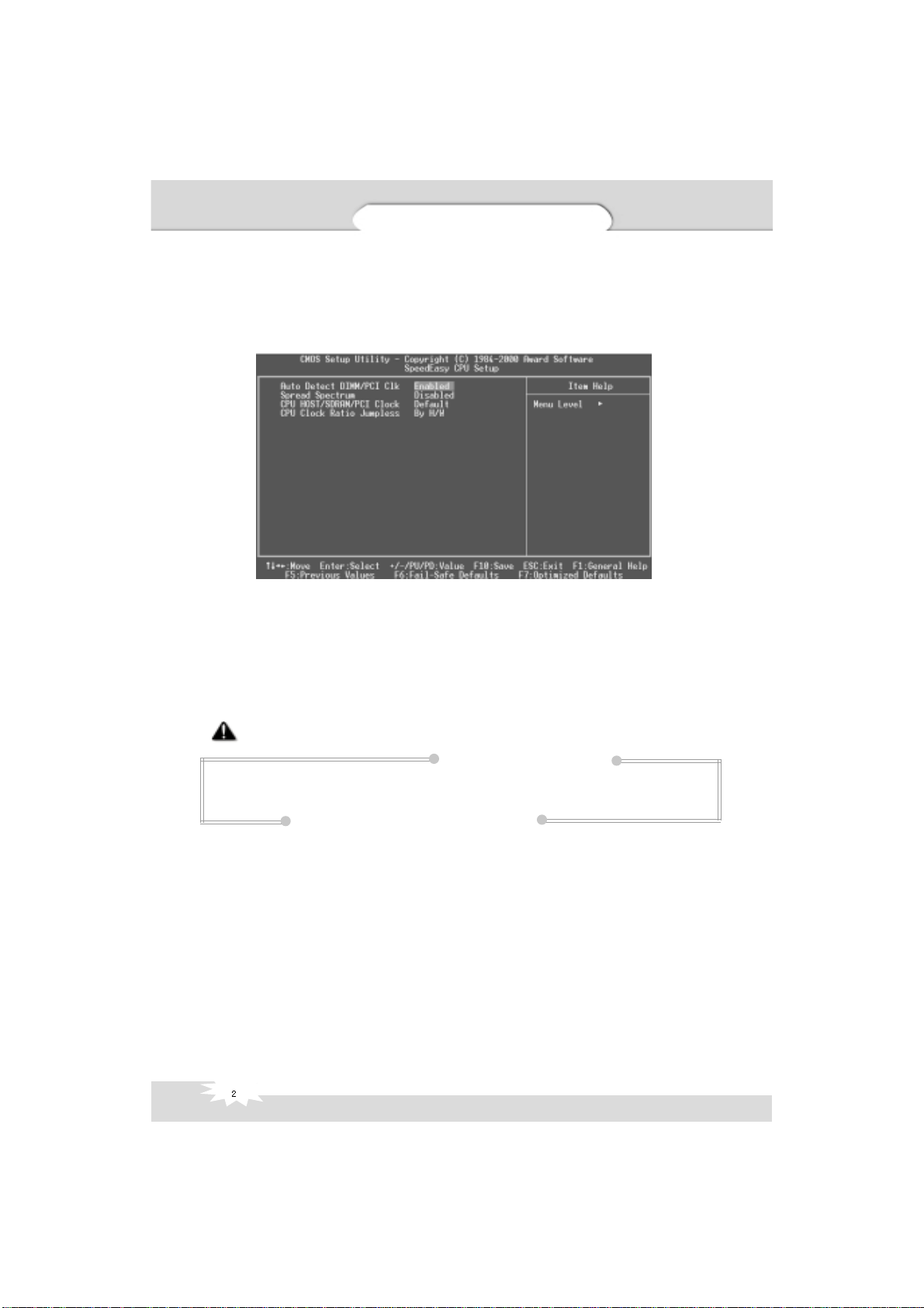
2. Pressez la touche «Suppr» pour entrer dans le setup du BIOS.
3. Dans le menu «SpeedEasy CPU Setup», réglez la vitesse de votre processeur (AT-
TENTION:il estrecommandé denepassélectionnerune fréquencesupérieure à
celle de votre processeur, nous déclinons toute responsabilité pour les dommages
quienrésulteraient)
4. Effectuez les autres réglages du BIOS selon votre configuration (nous vous
conseillons fortement de maintenir les réglages par défaut afin d’éviter toute manipu-
lation hasardeuse pouvant résulter en un dysfonctionnement). Pour plus
d’informations sur les fonctions du BIOS, vous pouvez consulter la version
françaisedu manuelsurle CD-ROM.
Superb 3L

Manual for Superb 3L
5. Pressez la touche F10 ou choisissez «Save and exit» pour enregistrer vos
paramètreset relancer lamachine.
6. Installezvotre systèmed’exploitation
7. Après installation, assurez-vous qu’il ne subsiste aucun conflit ou périphérique
inconnu dans votre système.
8. Installationdespilotes:
1. Express install
Ilest recommandé queles utilisateursinstallent ceprogrammeavec lesoptions debase
A. PiloteVGA
B. PiloteAudio codecAC97
2. Accessory
Les logiciels contenus dans ce répertoire sont :
A. DirectX7.0
B. QDIManageEasy
C. PC-Cillin
3. Browse CD
Vouspouvez voirle contenu duCD-ROM
Dansle répertoireUtility :
A. AWDFLASH.EXE
B. LF.EXE
C. CBLOGO
Dansle répertoireDocuments :
A. Adobe Acrobat Reader V3.0 – Ar32e301.exe
B. Manuels français *.doc
PC-Cillin98
De nouveaux virus apparaissent régulièrement, accroissant les chances que votre
PC soit infecté, aussi les anti-virus deviennent-ils essentiels. PC-Cillin 98 vous offre
une protection active permanente ainsi que des possibilités de scan manuel et de
nettoyage de virus. Rester à jour en terme de protection reste une partie cruciale de
la défense contre les virus, PC-Cillin vous offre la possibilité de mises à jour
régulières des listes de virus connus à partir du site de Trend Micro:
http://www.trend.com/download.pattern.htm ou
http://www.antivirus.com/download/pattern.htm
Installation du Superb 3L système

Manual for Superb 3L
Installation de PC-Cillin 98
PourWindows 95/98,lancer Setup.exedepuis lerépertoire duCD-ROM \Pccillin
\Win9x
PourWindows NT4.0, lancezSetup.exe depuisle répertoiredu CD-ROM\Pccillin
\WinNT4.0
Lenuméro desérie duproduitestPNEF-9991-6558-5857-5535
QDIManageEasy
Il est bien connu que garantir la sécurité et la fiabilité du PC est essentiel.
Spécialement de nos jours, gérer et surveiller le matériel est encore plus important
car les opérations et les échanges de données critiques entre ordinateurs et
réseaux sont monnaie courante.
Avec le développement de l’ordinateur, le système devient de plus en plus
complexe,enmême tempsle contrôle dumatériel doit êtrerenforcé. Aujourd’huiil
est possible de surveiller et contrôler votre matériel sous Windows 9x ou NT. QDI
ManageEasyest unoutil système,comme unpont entrel’OS etlematériel,utilisé
pour accéder au statut du matériel et exécuter des fonctions de contrôle. Ces
fonctions vous permettent de voir plus d’une centaine d’informations basiques sur
votre ordinateur et de surveiller des données clés sur la santé du PC en temps réel.
QDIManageEasyvous aideégalement à contrôlerà distance desmachines sous
réseau local. Avec QDI ManageEasy, vous améliorez votre niveau de gestion.
Installation de QDI ManageEasy v2.0
LancezSetup.exedepuislerépertoireduCD-ROM\QME2 pourinstallerQDI
ManageEasy2.0. L’assistant d’installationvous guiderapourle restede l’installation.
Pourplusd’informations surl’utilisationde QDIManageEasy v2.0, référez-vousà
l’aideenlignedeQDIManageEasyv2.0.
Le menu SpeedEasy
I. Insérez le processeur correctement.
II. Connectez les autres éléments du système (voir Installation).
III. Au démarrage du système, pressez la touche <Suppr> pour entrer dans le
Bios
IV. Entrezdanslemenu«CPUSpeedEasysetup»
Note: si vous ne déterminez pas la vitesse de votre unité centrale, votre
système fonctionnera par défaut ( 200MHz pour les CPU avec une
fréquence de Bus de 100MHz et 133MHz pour les CPU à 66MHz).
V. Sauvegardez et quittez le Bios.
Superb 3L

Manual for Superb 3L
CMOS Setup Utility – Copyright© 1984-1999 Award Software
SpeedEasy CPU Setup
Auto detect DIMM/PCI Clk : Enabled ItemHelp
SpreadSpectrum :Disabled
CPUHOST/SDRAM/PCIClk :Default MenuLevel>
CPUClockRatioJumpless : By H/W
Prévenir :
Le menu SpeedEasy vous fournit un ensemble de valeurs. Vous pouvez
sélectionnermanuellement lavitessedeCPUdans cemenu soitenmode
«SpeedEasy»soitenmode«JumperEmulation»(voirmanuel).
ATTENTION: Ne pas sélectionner une fréquence de fonctionnement du CPU
supérieure à celle indiquée par le constructeur. Nous déclinons toute
responsabilité pour tout dégât qui en résulterait.
Installation du Superb 3L système

Manual for Superb 3L
Chapter 1
Introduction
Chapter 1
Chapter 1
Introduction
Overview
The Superb 3L green mainboard utilizes the SiS630E chipset which integrates Ultra AGP
VGA for hardware 2D/3D video, provides highly integrated solution for fully compatible,
highperformance and cost-effectivePC/MATXPlatform. Thenew integratedtechnologies,
together with the software configurable AC’97 audio give customers an advanced, multi-
media solution at an extremely low price, It provides 66/100/133MHz system bus, Socket
370 CPU type support for all Intel Pentium®
III, Celeron(include medocina and Coppermine
128K/256K) and Cyrix-III processors. 66/100/133MHz SDRAM memory and NEC Virtual
channel memory are supported. It also provides advanced features such as wake-up on
LAN,wake-uponinternal/externalmodem,suspendtoRAMandkeyboardpasswordpower-
on function. The green function is in compliance with the ACPI specification. With QDI
innovations such as SpeedEasy, RecoveryEasy, LogoEasy , ManageEasy and BIOS-
ProtectEasy.
Key Features
Form factor
l MATX form factor of 244mm x188mm.
Microprocessor
l SupportsallIntel®PentiumIII(Coppermine)FC-PGAprocessorsat533/600EB/667/733/
800EB/866/933MHz/1000MHzand future processorswith 133MHzbus speed.
l Supports all Intel®Pentium III(Coppermine) FC-PGA processors at 500/550/600/650/
700/750/800/850MHz and future processors with 100MHz bus speed.
l SupportsallIntel®Celeron™ FC-PGAprocessorsat533/566/600/633/667/700/733MHz
and future processors with 66MHz bus speed.
l Supports all Intel®
Celeron™ PPGA processors at 300/300A/333/366/400/433/466/
500/533MHzwith 66MHzbusspeed.
l Supports later processors Cyrix-IIIat 500/533/550/600/667MHzand future processors
l Supports 66/100/133MHz host bus speed.
l CPU core frequency = Bus speed x3, x3.5, x4, x4.5, x5, x5.5, x6, x6.5, x7, x7.5,
x8, x8.5, x9, x9.5, x10, x10.5, x11, x11.5, x12.
l CPU core voltage adjustable from 1.3V to 3.5V through on-board swithcing voltage
regulator with VID (voltage ID)
Chipset
l SiS630E: Integrated AGP VGA for 2D/3D graphicsand video accelerators.

Manual for Superb 3L
Introduction
System memory
l Provides two 168 pin 3.3V buffered/unbuffered 66/100/133MHz DIMM sockets.
l Supports66/100/133MHz SDRAMand66/100/133MHzVCM(VirtualChannel
Memory)SDRAM
l Minimummemorysizeis 8MB,maximummemory sizeis1GB.
On-board IDE
l Supports two PCI PIO and Bus Master IDE ports.
l Two fast IDE interfaces supporting four IDE devices including IDE hard disks and
CD - ROM drives.
l Supports up to mode 4 timing.
l Supports “Ultra DMA/33”Synchronous DMA modetransferringupto 33 Mbytes/sec.
l Supports “Ultra DMA/66”Synchronous DMA modetransferringupto 66 Mbytes/sec.
l Integrated 16x32bit buffer for IDE PCI Burst Transfers.
On-chipI/O
l Use ITE 8705 super I/O chip.
l One floppy port supporting up to two 3.5” or 5.25” floppy drives with
360K/720K/1.2M/1.44M/2.88Mformat.
l Twohighspeed 16550fastcompatibleUARTs(COM1/COM2/COM3/COM4
selective) with 16-byte send/receive FIFOs.
l One enabled parallel port at the I/O address 378H/278H/3BCH with additional
bi-directionI/Ocapabilityandmulti-modeasSPP/EPP/ECP(IEEE1284compliant).
l Circuit protection provided, preventing damage to the parallel port when a
connected printer is powered up or operates at a higher voltage.
l Supports LS-120 floppy disk drive and Zip drive.
l All I/O ports can be enabled/disabled in the BIOS setup.
On-board Graphics
l Supports AGP 4 x 128 bits mode and AGP 2.0 compliant.
l Based on the onchip AGP graphics controller, integrated 2D/3D graphics and video
accelerators.
l Display memory share from DIMM memory up to 64M.
l Supports a maximum resolution of 1920X1200 at 80Hz.
On-chipAudio
l High quality Audio and AC’97/98 support.
l Compatible with Sound BlasterTM, Sound Blaster ProTM and Windows Sound
systemTM.
l Supports software-based Wavetable Synthesizer.
l Provides on-board Line-in jack, speaker-out jack and microphone-in jack.

Manual for Superb 3L
Chapter 1
Advanced features
l Provides on-board PS/2 mouse and PS/2 keyboard ports.
l Four USB ports supported.
l Provides infrared interface.
l Support PC99 color- coding connector Specification
l Supports Windows 98/Windwos 2000 software power-down.
l Supports wake-up on LAN and wake-up on external modem.
l Supports keyboard password power-on function.
lsupportssystemmonitoring(monitorssystemtemperature,CPUtemperature,voltages,
chassis intrusion and fan speed).
lProtects the system BIOS from being attacked by severe virus such as CIH, by
enabling“FlashWriteProtect” in CMOSsetup or closingtheJumper “JAV”.
BIOS
lLicensed advanced AWARD BIOS, supports flash ROM with 2M bit memory size,
plug and play ready.
lSupportsQDIinnovation:RecoveryEasy
lSupportsIDECD-ROMorSCSIbootup.
Green function
l Supports ACPI (Advanced Configuration and Power Interface).
l Supports three green modes: Doze, Standby and Suspend.
l Supports ACPI power status: S0, S1, S3(STR), S4(STD), S5(Soft-off).
Expansion slots
l 3 PCI slots.
l 1 AMR

Manual for Superb 3L
Introduction to New Features
BIOS Write Protection
The BIOS of the mainboard is contained inside the Flash ROM. Severe viruses such as
CIH virus are so dangerous that it may overwrite the BIOS of the mainboard. If the BIOS
has been damaged, the system will be unable to boot. We provide the following solution
which protects the system BIOS from being attacked by such viruses.
There are two choices which implements this function.
1. Set the jumper (JAV) as close, the BIOS can not be overwritten.
2. Set the jumper (JAV) as open, meanwhile set “Flash Write Protect” as Enabled in
AWARD BIOS CMOS Setup. In this way, the BIOS can not be overwritten, but the DMI
informationcan beupdated.
Ultra ATA/66
According to the previous ATA/IDE hard drive data transfer protocol, the signaling way to
send data was in synchronous strobe mode by using the rising edge of the strobe
signal. The Ultra ATA/33 protocol doubles the burst transfer rate from 16.6MB/s to
33.3MB/s, by using both the rising and falling edges of the strobe signal, this time Ultra
ATA/66 doubles the Ultra ATA burst transfer rate once again (from 33.3MB/s to 66.6MB/
s) by reducing setup times and increasing the strobe rate. The faster strobe rate
increases EMI, which cannot be eliminated by the standard 40-pin cable used by ATA
and Ultra ATA. To eliminate this increase in EMI, a new 40-pin, 80-conductor cable is
needed. This cable adds 40 additional ground lines between each of the original 40
groundand signal lines.The additional40 lineshelp shield thesignal fromEMI, reduce
crosstalk and improves signal integrity.
Ultra ATA/33 introduced CRC (Cyclical Redundancy Check), a new feature of IDE that
provides data integrity and reliability. Ultra ATA/66 uses the same process. The CRC
value is calculated by both the host and the hard drive. After the host-request data is
sent, the host sends its CRC to the hard drive, and the hard drive compares it to its
own CRC value. If the hard drive reports errors to the host, then the host retries the
commandcontainingtheCRCerror.
Ultra ATA/66 technology increases both performance and date integrity. However there
are basically five requirements for your system to run in Ultra ATA/66 mode:
1. The system board must have a special Ultra ATA/66 detect circuit, such as
Superb3Lmainboard.
2. The system BIOS must also support Ultra ATA/66.
3. The operating system must be capable of DMA transfers. Win95 (OSR2) and
Win98arecapable.
4. An Ultra ATA/66 capable, 40-pin, 80-conductor cable is required.
5. Ultra ATA/66 compatible IDE device such as a hard drive or CD-ROM drive.
Introduction

Manual for Superb 3L
Suspend to RAM
Suspend to RAM is a cost-effective, optimal implementation of the Advanced Configura-
tion and Power Interface (ACPI) 1.0 specification, which makes a PC’s power consump-
tion drop to the lowest possible level and enables quick wakeup. When the system is in
Suspend-to-RAMstatus,the systemcontextis maintainedin system memory,the system
consumes only a small fraction of the power used for full operation. Instead of shutting
down the system to save power when not in use and then having to reboot later, Sus-
pend-to-RAM solution enables the system to quickly wake up, restoring all applications
and features, enabling operation in a few seconds.
Toimplement thisfunction, thefollowing requirmentsareessential:
1. Power supply requirements: The current of 5VSB line of the power supply should be
morethan0.75A.
2. TheBIOS option“ACPIfunction”shouldbe enabled,and“ACPI SuspendType”should
be set as S3 in AWARD BIOS CMOS setup. Refer to page 35 for detail
3. An ACPI-enabled operating system such as Windows 98 or Windows 2000 family is
needed.
a.InordertoinstallACPI-enabledWindows98operatingsystem,thesetupcommand
should be typed as shown below:
D:\SETUP /P J
(This manual assumes that your CD-ROM device driver letter is D:).
4. Three ways to enter Suspend-to-RAM status under ACPI-enabled Windows 98:
lClick Start -> Shut down -> Standby to enable the system to enter Suspend-to-
RAMstatus.
lClick Start -> Setup -> Control Panel -> Power Management -> Advanced and
choose Standby item, the system will enter Suspend-to-RAM status when you
press power button.
lFrom Power Management Properties in Control Panel, set the latency time in
System Standby, the system will enter Suspend-to-RAM status when time out.
The same ways used to power up the system can be used to wake up the system from
Suspend-to-RAM status. For example, pushing the power button, through the Wake-on-
LAN,Wake-on-Modemfunction orRTCAlarm.
Chapter 1

Manual for Superb 3L
PC-133 Memory
PC133SDRAMUnbuffered DIMMdefinesthe electricalandmechanicalrequirementsfor
168-pin,3.3 Volt, 133MHz,64/72-bit wide, UnbufferedSynchronousDRAM DualIn-Line
MemoryModules (SDRAMDIMMs). Relatively, the peakbandwidthof PC-133memoryis
the 33% higher than PC-100 memory. These latest SDRAMs are necessary to meet the
enhanced133MHzbusspeedrequirement.
Introduction

Manual for Superb 3L
Chapter 2
Installation Instructions
chapter 2
Chapter 2
Installation Instructions
Thissection coversExternalConnectors, JumperSettings andMemory Configuration.Re-
ferto the mainboardlayout chartfor locations ofall jumpers, externalconnectors, slotsand
I/O ports. Furthermore, this section lists all necessary connector pin assignments for your
reference. The particular state of the jumpers, connectors and ports are illustrated in the
following figures. Before setting the jumpers or inserting these connectors, please pay
attention to the directions.
Be sure to unplug the AC power supply before adding or removing expansion
cards or other system peripherals, otherwise your mainboard and expansion
cards might be seriously damaged.
External Connectors
PS/2 Keyboard Connector, PS/2 Mouse Connector
PS/2 keyboard connector is for the usage of PS/2 keyboard. If using a standard AT size
keyboard, an adapter should be used to fit this connector. PS/2 mouse connector is for the
usageof PS/2mouse.
USB1,USB2
Two USB ports are available for connecting USB devices.
Parallel Port Connector, Serial Port Connector, Monitor Output Con-
nector (Parallel, UART1, VGA Monitor)
The parallel port connector can be connected to a parallel device such as a printer, while
the serial port connector can be connected to a serial port device such as a serial port
mouse. The monitor output connector is for output to a VGA-compatible device. You can
enable/disable them and choose the IRQ or I/O address in “Integrated Peripherals” from
AWARD BIOS SETUP.
Parallel Port
UART1
PS/2MouseConnector
PS/2KeyboardConnector
VGA
USB2
USB1

Manual for Superb 3L
UART2
Theserialport UART2isnot locatedontheback panel.Therefore,weprovidea9-pinribbon
cable with bracket for UART2 port. (manufacturing option)
USB3,USB4
Two USB ports are not available on the back panel. Therefore, we provide a 10-pin ribbon
cable with bracket to connect Built-in on-board USB header. ( manufacturing option)
Line-in jack, Microphone-in jack, Speaker-out jack and
MIDI/Joystick connector
The Line-in jack can be connected to devices such as cassette or minidisc player for
playbackor recording.TheMicrophone-in jackcan beconnected toamicrophone forvoice
input. The Speaker-out jack allows you to connect speakers or headphones for audio
outputfrom theinternal amplifier.
The MIDI/Joystick connector allows you to connect a game joystick or a MIDI device.
Installation Instructions
MIDI/Joystick
Speaker-out Line-in Microphone-in
UART2
1
1
+5v
T1-
T1+
GND
GND
GND
GND
T0+
T0-
+5v
Table of contents
Other QDI Motherboard manuals

QDI
QDI K7VM400M Pro Series User manual

QDI
QDI Brilliant IV User manual

QDI
QDI PlatiniX 2E/333 User manual

QDI
QDI Pentium P5I430TX/IIB TITANIUM IIB User manual

QDI
QDI Advance 5 User manual

QDI
QDI PlatiniX 4X User manual

QDI
QDI LegenX 8 User manual

QDI
QDI P5I865PE User manual

QDI
QDI Advance 6T User manual

QDI
QDI P5I945P User manual

QDI
QDI SynactiX 1E User manual

QDI
QDI XT4500 Series User manual

QDI
QDI PlatiniX 1 User manual

QDI
QDI Legend-III P6I440LX/AV User manual

QDI
QDI GeniuX 1 User manual

QDI
QDI XV915 Series User manual

QDI
QDI P51437/250a User manual

QDI
QDI Advance 10TM User manual

QDI
QDI CenturieX 1 User manual

QDI
QDI K8N4 Series User manual