MAINTENANCE - TECHNICAL DATA
TECHNICAL DATA
(1)
Maximum rated value at normal use or in short circuit.
(2)
With battery charger not supplied by the AC network.
(3)
At 50% of the maximum rated output current on resistive load.
(4)
Each output can supply the maximum value of nominal current. The sum of the currents supplied from each output can not exceed the maxi-
mum nominal value of the equipment.
(5)
With supply voltage equal to 230 Vac and output current equal to the maximum nominal value.
(6)
With supply voltage equal to 120 Vac and output current equal to the maximum nominal value.
(7)
Protection may be inefficient in some operative conditions.
MAINTENANCE
The battery charger does not need any maintenance. To ensure optimum performance from the equipment, once a year
check the cables and the electrical connections.
QUICK®RESERVES THE RIGHT TO MODIFY THE TECHNICAL CHARACTERISTICS OF THE EQUIPMENT AND THE CONTENTS OF THIS MANUAL WITHOUT PRIOR NOTICE.
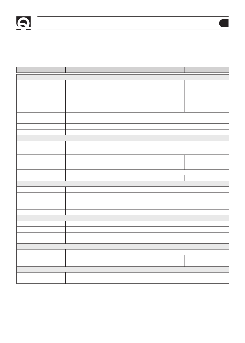
MODEL SBC 140 NRG+ FR SBC 250 NRG+ FR SBC 300 NRG+ FR SBC 500 NRG+ FR SBC 365 NRG+ FR
OUTPUT CHARACTERISTICS
Maximum output current
(1)
12 A 25 A 30 A 40 A 15 A
Charge ABSORPTION voltage
• 14,1 Vdc EL open
• 14,4 Vdc EL sealed / Gel / AGM
• 14,7 Vdc Optima®
• 28,2 Vdc EL open
• 28,8 Vdc EL
sealed
/ Gel / AGM
• 29,4 Vdc Optima®
Charge FLOAT voltage
• 13,4 Vdc EL open
• 13,6 Vdc AGM
• 13,8 Vdc EL sealed / Gel / Optima®
• 26,8 Vdc EL open
• 27,2 Vdc AGM
• 27,6 Vdc EL sealed / Gel / Optima
®
DC absorption from the batteries
(2)
< 3,5 mA
Residual ripple
(3)
< 100 mV RMS
Charging characteristics Automatic in three stages IUoU
Number of outputs (4) 2 3
INPUT CHARACTERISTICS
Supply voltage 264 ÷ 83 Vac,
with power reduction under 108 Vac
Frequency 45÷66 Hz
Maximum absorption
(230/240 Vac) (5) 0,9 A 1,8 A 2,2 A 2,7 A 2,0 A
Maximum absorption (120 Vac) (6) 1,7 A 3,4 A 4,2 A 5,3 A 4,0 A
Power factor (cos ϕ) (5) 1,00
Efficiency (5) ≥83% ≥84% ≥85% ≥87% ≥86%
PROTECTIONS
Reverse polarity (7) Yes, through fuse
Overload Yes
Output short circuit Yes
Overvoltage in output Yes
Overheating Yes
AMBIENT CHARACTERISTICS
Operating temperature -15 ÷ +70 °C, with linear power reduction over +45 °C
Noise level < 43 dbA @ 1 m < 45 dbA @ 1 m
Cooling Variable fan speed
Humidity Max. 95% RV without condensation
CASE
Material Aluminium
Dimensions (WxHxD) 114 x 187 x 71 mm 114 x 252 x 71 mm 114 x 252 x 71 mm 114 x 275 x 71 mm 114 x 252 x 71 mm
Weight 1,1 kg 1,6 kg 1,6 kg 1,8 kg 1,6 kg
GENERAL
Safety standard EN 60335-2-29
EMC Standard EN 55022/B - FCC TITLE 47 PART 15 SUBPART B CLASS B