RADWAG TWM4 User manual


2
MARCH 2021

3
PRECAUTIONS
Prior to installation, operation or maintenance activities, carefully read this user
manual. Follow the instructions strictly.
Prior to the first use, carefully read this user manual. Use the device only
as intended.
Place loads in the centre of the weighing pan.
Load the weighing pan with loads of gross weight which does not exceed
the maximum capacity.
Mind not to leave heavy loads on the weighing pan for longer periods
of time.
Protect the scale against considerable temperature variation, solar and UV
radiation, substances causing chemical reactions.
The scale must not be operated in hazardous areas endangered with
explosion of gases, and in dusty environments.
In the case of damage, immediately unplug the device from the mains.
The scale to be decommissioned must be decommissioned in accordance
with valid legal regulations.
If the scale is to be operated in conditions that are difficult due to
electrostatics (e.g. printing house, packing centre, etc.), you must connect
it to the earth wire. To enable this, the device features functional earthing
terminal, marked with symbol.

4
CONTENTS
1. INTENDED USE .................................................................................................................................................5
2. WARRANTY CONDITIONS ...............................................................................................................................5
3. MAINTENANCE..................................................................................................................................................5
3.1. Cleaning Powder-Coated Components.......................................................................................................6
3.2. Cleaning Stainless Steel Components........................................................................................................6
3.3. Cleaning ABS Components.........................................................................................................................6
4. SERVICE AND REPAIR.....................................................................................................................................6
5. RECYCLING.......................................................................................................................................................7
6. MECHANICAL DESIGN..................................................................................................................................... 7
6.1. 1-Load-Cell Scales......................................................................................................................................7
6.2. Multiple-Load-Cell Scales............................................................................................................................7
6.3. Scales with Load-Cell Modules...................................................................................................................8
6.4. Dimensions..................................................................................................................................................8
6.5. Models.........................................................................................................................................................8
6.6. Connectors ..................................................................................................................................................8
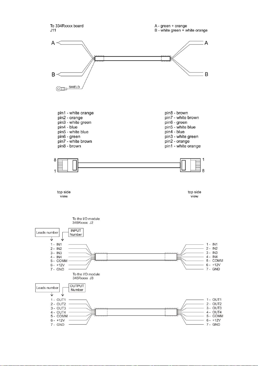
6.6.1. Pin Arrangement...............................................................................................................................9
6.6.2. Diagrams of connection cables........................................................................................................9
6.7. Inputs / Outputs .........................................................................................................................................11
6.7.1. Technical Specifications.................................................................................................................11
6.7.2. Schematic Diagrams ......................................................................................................................11
6.7.3. Input / Output Signals.....................................................................................................................11
7. INSTALLATION................................................................................................................................................ 12
7.1. Unpacking and Installation........................................................................................................................12
7.1.1. 1-Load-Cell Plstform Scales of TWM4-x Series.............................................................................12
7.1.2. Platform Scales of TWM4-x.4.xx.C, TWM4-x.4.xx.H, TWM4-x.4.xx.H/Z Series ..........................12
7.1.3. Ramp Scales of TWM4-x.4N Series ..............................................................................................12
7.2. Levelling: 1-Load-Cell Platform Scales.....................................................................................................13
7.3. Levelling: 4-Load-Cell Platform Scales.....................................................................................................14
7.4. Start-Up .....................................................................................................................................................14
8. MwManager HOME SCREEN .........................................................................................................................15
9. OPERATING THE MENU................................................................................................................................. 16
10. WEIGHING .....................................................................................................................................................16
10.1. Good Weighing Practice: 1-Load-Cell Platform Scales..........................................................................17
10.2. Good Weighing Practice: Custom Scales...............................................................................................17
10.3. Zeroing ....................................................................................................................................................18
10.4. Taring ......................................................................................................................................................19
10.5. Dual Range Devices................................................................................................................................ 19
11. TECHNICAL SPECIFICATIONS....................................................................................................................19
12. ERROR MESSAGES .....................................................................................................................................20

5
1. INTENDED USE
The scales are a response to growing market demands for an instrument
offering simplicity of operation and weighing process automated to the
maximum. Due to use of the MW-04 mass converter, the scales are a perfect
solution for numerous industry applications. The converter features a metal
housing, this enables operation in high humidity and vast temperature range,
from -10C to +40C. It communicates with various devices via the following
interfaces: RS232, RS485, Ethernet, Profibus, and Modbus protocol.
The TWM4 scale is equipped with 4 optoisolated inputs and 4 Opto MOS
outputs. It is powered by 100-240VAC mains voltage.
Operation of the TMW4 scale via PC is carried out using ’MwManager’
software. For more information on the ‘MwManager’software read MwManager
manual.
2. WARRANTY CONDITIONS
A. RADWAG is obliged to repair or exchange all elements that appear to be
faulty by production or by construction.
B. Defining defects of unclear origin and means of their elimination can only
be realized with the assistance of the manufacturer and the user
representatives.
C. RADWAG does not bear any responsibility for damage or losses
resulting from unauthorized or inadequate performing of production or
service processes.
D. The warranty does not cover:
mechanical damage caused by product exploitation other than
intended, damage of thermal and chemical origin, damage caused by
lightning, overvoltage in the power network or other random event,
inappropriate cleaning habits.
E. Loss of warranty takes place if:
a repair is carried out outside RADWAG authorized service point,
service claims intrusion into mechanical or electronic construction by
unauthorized people,
the scale does not bear security seal stickers.
F. Warranty conditions outline the warranty period for rechargeable
batteries attached to the device for 12 months.
G. For detailed warranty conditions read the service card.
H. Contact with the central authorized service: +48 (48) 386 63 30.
3. MAINTENANCE
In order to clean the weighing instrument risk-free, it is necessary to disconnect
the device from the mains.

6
With this condition met, uninstall the weighing pan and other detachable
components.
Cleaning the weighing pan while still installed may cause
damage of the measuring system.
3.1. Cleaning Powder-Coated Components
Avoid using cleansers containing any corrosive chemicals, e.g. bleach
(with chlorine). Do not use cleansers containing abrasive substances.
Always remove the dirt using microfiber cloth, do it in order to avoid damage
of protective coating. In the case of a daily maintenance:
1. Remove the dirt using cloth dipped in warm water.
2. For best results, add a little bit of dishwashing detergent.
3.2. Cleaning Stainless Steel Components
Avoid using cleansers containing any corrosive chemicals, e.g. bleach
(with chlorine). Do not use cleansers containing abrasive substances.
Always remove the dirt using microfiber cloth, do it in order to avoid damage
of protective coating. In the case of a daily maintenance:
1. Remove the dirt using cloth dipped in warm water.
2. For best results, add a little bit of dishwashing detergent.
3.3. Cleaning ABS Components
To clean dry surfaces and avoid smudging, use clean non-colouring cloths
made of cellulose or cotton. You can use a solution of water and detergent
(soap, dishwashing detergent, glass cleaner). Gently rub the dirty surface and
let it dry. Repeat the cleaning process if necessary.
In the case of hard to remove contamination, e.g. residues of adhesive, rubber,
resin, polyurethane foam etc., you can use special cleaning agents based on
a mixture of aliphatic hydrocarbons that do not dissolve plastics. Before using
the cleanser for all surfaces we recommend carrying out tests. Do not use
cleansers containing abrasive substances.
4. SERVICE AND REPAIR
In the case of any sign of damage, it is necessary
to disconnect the device form the mains immediately.
The damaged component must be replaced or repaired by
RADWAG service directly.

7
In the case of any problems with correct operation of the scale, contact the
closest manufacturer's service point. In the case of defects, deliver the faulty
product to the manufacturer's service point. If the product cannot be delivered
to the manufacturer's service point, call the service and report the defect.
Repair scope and method will be set up.
The user is NOT ALLOWED to carry out any kind of repair
of the device himself/herself. Any attempt of scale
modification, repair etc., by unauthorized persons, will result
with loss of validity of manufacturer-issued certificates,
declarations and warranty.
5. RECYCLING
TWM4 scales must be recycled, they are not to be treated as a regular
household waste. Scales to be decommissioned must be decommissioned
in accordance with valid legal regulations.
6. MECHANICAL DESIGN
6.1. 1-Load-Cell Scales
1-load-cell TWM4 scale is intended to carry out fast and precise mass
measurement of up to 300 kg loads. Its characteristic feature is a platform with
one load cell only. The platform is equipped with a stainless steel weighing
pan. Depending on a scale model, the cross and base are made of either
stainless steel or powder-coated steel.
6.2. Multiple-Load-Cell Scales
Multiple-load-cell TWM4 scale is intended to carry out fast and precise mass
measurement of large loads.
Its characteristic feature is a platform equipped with numerous load cells,
usually four. The platform, depending on a scale model, is made of stainless
steel or powder-coated steel, it features customized mechanical design suiting
particular customer's requirements (pallet, beam, platform scales).

8
6.3. Scales with Load-Cell Modules
TWM4 scale with load cell modules is intended to carry out mass measurement
of silos. Modules are built into construction of ground-fixed silo's support.
In most cases, the scale design includes 3-4 load cell modules. The modules,
depending on the model, are made of stainless or galvanized steel.
6.4. Dimensions
For overall dimensions read product card of a respective scale, the product
cards are to be found on RADWAG website www.radwag.pl.
6.5. Models
TWM4 models:
MODEL
TWM4-1
TWM4-2
TWM4-3
Communication interface
RS232, Ethernet
RS232, RS485
RS232, PROFIBUS
4IN/4OUT module*
1
1
-
RS485 module
-
1
-
PROFIBUS module*
-
-
1
DP-5 platform module
2
2
2
*) - PROFIBUS and 4IN/4OUT modules are installed interchangeably (the device is equipped with
one of them).
6.6. Connectors
MW-04 mass converter connectors

9
1
PG11 cable gland for platform 1.
2
PG11 cable gland for platform 2.
3
PG11 cable gland for platform 3.
4
PG11 cable gland for platform 4.
5
M12 8P connector for RS232.
6
M16 cable gland for Ethernet/RS485 cable (conditioned by the scale model).
7
M16 cable gland for 4IN cable (option: PROFIBUS IN connector).
8
M12 cable gland for power cord 230VAC.
9
M16 cable gland for 4IN cable (option: PROFIBUS OUT connector).
6.6.1. Pin Arrangement
RS232
Pin2 –RxD
Pin3 –TxD
Pin5 –GND
PROFIBUS IN
(male)
Pin1 –NC
Pin2 –A
Pin3 –NC
Pin4 –B
Pin5 –NC
PROFIBUS OUT
(female)
Pin1 - +5V
Pin2 –A
Pin3 –GND
Pin4 –B
Pin5 –NC
6.6.2. Diagrams of connection cables
'Mass converter' –,computer' cable (PT0020)

10
'Mass converter' –'RS485' cable (PT0012)
'Mass converter' –,Ethernet' cable (PT0224)
'Mass converter' –,4IN/4OUT' cable (PT0209)

11
6.7. Inputs / Outputs
6.7.1. Technical Specifications
Output parameters
Output quantity
4
Output type
OptoMOS
Maximum output current
0.2 A DC
Maximum output voltage
50 V DC
Input parameters
Input quantity
4
Input type
Optoisolated
Input voltage range
5 - 24 V DC
6.7.2. Schematic Diagrams
4 inputs
4 outputs
6.7.3. Input / Output Signals
The signals are transmitted on two cables (cable one for inputs, cable two for
outputs). See the table below for distribution of signals on cable wires.
INPUTS
OUTPUTS
Wire number
Signal
Wire number
Signal
1
IN1
1
OUT1
2
IN2
2
OUT2
3
IN3
3
OUT3
4
IN4
4
OUT4
5
COM
5
COM
6
+12V
6
+12V
7
GND
7
GND
+12VDC and GND signals are connected to the power supply of the MW-04 mass converter.

12
7. INSTALLATION
7.1. Unpacking and Installation
Mind not to damage cable connecting the mass converter
and a weighing platform.
7.1.1. 1-Load-Cell Plstform Scales of TWM4-x Series
Take the scale out of the packaging.
Place the scale on a flat and even surface. Keep it far away from any
sources of heat.
Remove transport locks and install the weighing pan:
7.1.2. Platform Scales of TWM4-x.4.xx.C, TWM4-x.4.xx.H,
TWM4-x.4.xx.H/Z Series
Take the scale out of the packaging (pallet).
Place the scale on a flat and even surface. Keep it far away from any
sources of heat.
Remove transport locks (if installed):
Fix the feet (if not installed):
7.1.3. Ramp Scales of TWM4-x.4N Series
Take the scale out of the packaging (pallet).
Prior to installation, mount a steel bracket (2) onto a foot base (1), do it
using an expanding ring (3), next screw the foot base (1) onto a foot pin
(4).

13
Place the scale on an even surface, install ramps onto the steel brackets.
Remove ramps, looking through bracket holes mark spots where openings
for anchor bolts are to be made.
Drill openings, mount steel brackets to the ground.
7.2. Levelling: 1-Load-Cell Platform Scales
It is necessary to level the scale, do it by turning its feet. Keep turning the feet
until the air bubble takes central position.
5 - nut
6 - washer
7 - centring cone
8 - anchor bolt

14
7.3. Levelling: 4-Load-Cell Platform Scales
To level the scale use the levelling feet and the level indicator. Each foot can
be turned left and right, turning causes tilt. Adjustment span of the scale level is
narrow therefore the correct level is obtained using steel washers which are to
be put under the feet.
Keep turning the feet until the air bubble takes central position:
7.4. Start-Up
Plug the power cord to the mains.
Wait for connection to be established between the scale and the
‘MwManager’software, read the weighing result.
Weighing result window
Symbols:
Zero indication.
Stable weighing result.
Net
Tare function has been used.
Weighing unit.
Weighing platform number.

15
Keys:
Press to zero the scale
Press to tare the scale
Press to select a weighing platform if the mass converter communicates
with more than one platform.
Zero and tare functions are available for the currently
selected platform.
8. MwManager HOME SCREEN
The procedure of communication establishing and a detailed
description of connection between the scale and the
’MwManager’software is to be found in the ‘MwManager’ user
manual.

16
9. OPERATING THE MENU
In order to operate the ’MwManager’software use a mouse and a PC
keyboard.
All temporary parameters that are not saved to the mass converter are marked
red.To confirm the entered parameter values press <ENTER> key on the
keyboard.
Buttons:
MW-01 mass converter, TWM4 scale.
MW-04 mass converter, TWM4 scale.
Exit button. Press to close the program. The following message is displayed:
<Close program?> (where: <Yes> - press to stop the program; <No> -
press to go to the program menu back).
Connect button. Press to connect with the scale. Upon establishing
connection, the button changes its function to „Disconnect” and the colour
to green.
Disconnect button. Press to disconnect with the scale. Upon disconnection,
the button changes its function to „Connect” and the colour to red.
Refresh button. Parameter structure readout. In the case of no unsaved
modifications, at the readout of parameter structure, the following message
is displayed: <Readout successful>. In the case of some unsaved
modifications, at the readout of parameter structure, the following information
is displayed: <Unsaved modifications will be lost. Continue?> (where:
<Yes> - press to read parameter structure wherein the unsaved
modifications are lost; <No> - press to go to the program menu back).
Parameter import. For detailed information read the software user manual.
Parameter export. For detailed information read the software user manual.
Save button. Press to save parameter values. The following message is
displayed: <Save parameters?> (where: <Yes> - record of the parameters
confirmed with <Changes saved> message; <No> - press to go to the
program menu back).
10. WEIGHING
Load the weighing pan. Read the result when stability marker is displayed.

17
10.1. Good Weighing Practice: 1-Load-Cell Platform Scales
In order to guarantee a long-term operation, wherein correct measurements are
provided, the following principles must be adhered to:
Load the weighing pan steadily, avoid
applying mechanical shocks.
Place the loads centrally on the
weighing pan (eccentricity errors are
specified by EN 45501 standard, point
3.6.2).
Do not apply concentrated force (total
load in one point).
Avoid side loading, in particular side
shocks.
10.2. Good Weighing Practice: Custom Scales
It is forbidden to apply load other than intended for a particular scale:
beam scales; self-supporting, rigid load or load placed in rigid load-
transferring packaging:

18
pallet scales (load placed on EUR-pallet loaded using pallet truck); middle
block of pallet placed on the scale must remain unsupported:
ramp scales (trucks used in meat plants); it is necessary to select platform
matching the span of truck casters, this is to make sure that in the case
of trucks of weight close to the maximum capacity, the load is transferred
onto the platform close to load-carrying sections (profiles):
10.3. Zeroing
To zero mass indication press key. Zero indication and the following
pictograms are displayed: and .
Zeroing operation means determining new zero point, recognized by
the weighing device as precise zero. The instrument can be zeroed only when
the indication is stable.
Indication can be zeroed only within ±2% range of the
maximum capacity. If the zeroed value is greater than ±2%
of the maximum capacity, then the software displays
a respective error message: <Err2>.

19
10.4. Taring
To determine net weight value, load the weighing pan with a packaging, wait
for a stable indication and press key. Zero indication and the following
pictograms are displayed: Net and . The scale has been tared.
Remember not to exceed the maximum capacity, i.e. sum of tare weight value
and load weight value must be lower than the maximum capacity value.
Upon unloading of the weighing pan, the sum of tared masses with minus sign
is displayed.
It is impossible to tare zero or negative values. When you tare
zero or negative values the scale responds with the following
message: <Err3>.
10.5. Dual Range Devices
N/A in case of single range scales
Switching from weighing with the accuracy of the 1 weighing range to
weighing with the accuracy of the 2 weighing range takes place automatically
upon exceeding Max of the 1 weighing range.
In case of dual range scales:
upon switching to weighing with the accuracy of the 1 weighing range,
pictogram/marker is displayed on the left,
upon switching to weighing with the accuracy of the 2 weighing range,
pictogram/marker is displayed on the left.
Switching from weighing with the accuracy of the II weighing range
to weighing with the accuracy of the I weighing range takes place
automatically upon unloading of the weighing pan and returning to AUTOZERO
–( pictogram/marker is displayed).
11. TECHNICAL SPECIFICATIONS
For technical specifications of respective scales go to RADWAG website
www.radwag.pl.

20
12.ERROR MESSAGES
Err2
Value out of zero range.
Err3
Value out of tare range.
Err4
Calibration mass or start mass beyond the acceptable range (1% for weight, 10
for start mass).
Err8
Taring/zeroing time out of range.
NULL
Zero value from converter.
FULL
Weighing range exceeded.
HI
Display capacity out of range.
LH
Start mass error, indication out of range (-5% –+15% of start mass).
This manual suits for next models
3
Table of contents
Other RADWAG Scale manuals

RADWAG
RADWAG APP 35.R2 User manual

RADWAG
RADWAG AS R2 User manual

RADWAG
RADWAG PM 4Y User guide

RADWAG
RADWAG AS series User manual

RADWAG
RADWAG WPT/4 User manual

RADWAG
RADWAG WLC/C2 User manual

RADWAG
RADWAG PS 5Y.M User guide

RADWAG
RADWAG WLC A1 User guide

RADWAG
RADWAG AS series User manual

RADWAG
RADWAG AS R2.PLUS User manual

RADWAG
RADWAG R Series User manual

RADWAG
RADWAG HX5.EX User manual

RADWAG
RADWAG WLC User manual

RADWAG
RADWAG WLC A1 User guide

RADWAG
RADWAG TMC 0,3/0,6 KTPS/H1 User manual

RADWAG
RADWAG WLC/A1/C/2 User manual

RADWAG
RADWAG ITKU-20-02-01-12-A User manual

RADWAG
RADWAG WLY Series User manual

RADWAG
RADWAG AS X2 PLUS User guide

RADWAG
RADWAG AS R2 PLUS User guide