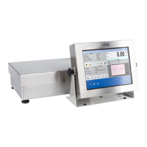
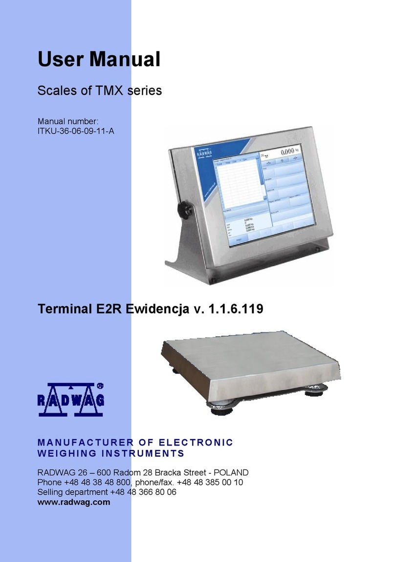
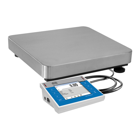
RADWAG WPW/E User manual

Manual number
ITKU-11-03-11-11-A
Labelling scales:
•WPW/E
•WPW/E/H
MANUFACTURER OF ELECTRONIC
WEIGHING INSTRUMENTS
RADWAG 26 – 600 Bracka 28 Street - POLAND
Radom,tel.+48483848 800, tel/fax +4848 385 00 10,
sales department +4848 366 80 06
www.radwag.com

- 2 -
NOVEMBER 2011

- 3 -
TABLE OF CONTENT
1. NTENDED USE .......................................................................................................................................7I
2. PRECAUTIONARY MEASURES..............................................................................................................8
2.1. Precautions.................................................................................................................................................................8
2.2. Accumulator / battery pack..........................................................................................................................................8
2.3. Operation in a strong electrostatic field.......................................................................................................................9
2.4. Washing scales intended for meat processing industry..............................................................................................9
3. WARRANTY CONDITIONS....................................................................................................................11
4. MAIN DIMENSIONS ...............................................................................................................................12
5. DESCRIPTON OF CONNECTORS.........................................................................................................12
6. UNPACKING AND MOUNTING..............................................................................................................13
7. GETTING STARTED ..............................................................................................................................13
8. KEYBOARD............................................................................................................................................14
9. PICTOGRAMS........................................................................................................................................14
9.1. Battery charge indication...........................................................................................................................................15
10. FUCTIONS OF KEYS...........................................................................................................................15
11. MENU - PARAMETERS .......................................................................................................................16
11.1. Overview of parameters..........................................................................................................................................16
11.2. Navig ting within the menu level ............................................................................................................................20a
11.2.1. Keyboard .....................................................................................................................................................20
1.2.2. Quick access ...............................................................................................................................................211
11.3. Return to weighing..................................................................................................................................................21
12. WEIGHING ...........................................................................................................................................22
12.1. Operating conditions...............................................................................................................................................22
12.2. Tarring ....................................................................................................................................................................23
12.3. Inscribing tare value................................................................................................................................................23
12.4. Zeroing....................................................................................................................................................................24
12.5. Weighings in two ranges.........................................................................................................................................25
12.6. Toggli g between weight units................................................................................................................................25n
12.6.1. Selection of basic unit..................................................................................................................................25
2.6.2. Toggling between weight units.....................................................................................................................261
12.7. Switching between platforms..................................................................................................................................26
13. MAIN PARAMETERS...........................................................................................................................27
13.1. Filtering level...........................................................................................................................................................27
13.2. Median filter............................................................................................................................................................28
13.3. Dosing filter setting.................................................................................................................................................28
13.4. Minimal mass parameter ........................................................................................................................................30
13.5. Tare function...........................................................................................................................................................31
13.6. Autozero .................................................................................................................................................................32
14. PORTS PARAMETERS........................................................................................................................33
14.1. RS 232, RS 485 setting..........................................................................................................................................33
14.1.1. Baud rate of RS 232....................................................................................................................................33
14.1.2. Baud rate of RS 485....................................................................................................................................34
14.1.3. RS 232 parameters......................................................................................................................................35
4.1.4. Setting of RS 485 parameters .....................................................................................................................361
14.2. ETHERNET setting.................................................................................................................................................37
15. EXTERNAL DEVICES..........................................................................................................................38
15.1. Coop ation with a computer..................................................................................................................................38er
15.1.1. Select the communication port scale-computer...........................................................................................38
15.1.2. Type of printout scale – computer ...............................................................................................................39
15.1.3. Address setting............................................................................................................................................40
15.1.4. Commands operating of communication protocol .......................................................................................40
15.1.5. Cooperation with „E2R System”...................................................................................................................41
15.1.5.1. ing „E2R System”........................................................................................................................41Enabl
15.1.5.2. uffer for weighings .............................................................................................................................42B
15.1.5.3. The lock of product change..................................................................................................................43
15.2. Coop ation with printers........................................................................................................................................43er
5.2.1. Communication port scale - printer..............................................................................................................431
15.3. Coop ation with a barcode scanner......................................................................................................................44er
15.3.1. Select a communication port for the scanner ..............................................................................................44
15.3.2. Setting the START parameter .....................................................................................................................45
15.3.3. Setting the LENGTH parameter...................................................................................................................46

- 4 -
15.4. Coop ation with a transponder card reader..........................................................................................................46er
15.4.1. Selecting of communication port..................................................................................................................47
5.4.2. Procedure of ascribing card numbers to operators......................................................................................471
15.5. Coop ation with an additional display...................................................................................................................48er
15.5.1. Selecting a communication port...................................................................................................................48
15.5.2. Selecting an additional display type.............................................................................................................49
16. DATE / TIME SETTING ........................................................................................................................50
16.1. Time view................................................................................................................................................................50
16.2. Time setting............................................................................................................................................................50
16.3. Date format.............................................................................................................................................................51
17. PRINTOUTS.........................................................................................................................................52
17.1. Printout type............................................................................................................................................................52
17.2. Printout of stable / unstable data............................................................................................................................53
17.3. Checkweighing mode .............................................................................................................................................54
17.4. Non-standard printouts...........................................................................................................................................55
17.5. Designing non-standard printouts...........................................................................................................................55
17.6. Texts non-standard printouts..............................................................................................................................56in
17.6.1. Code format.................................................................................................................................................56
17.6.2. Variables appearance in all modes..............................................................................................................57
17.6.3. Variables for the labelling mode only...........................................................................................................58
17.6.4. Variables for printing out weighings from the database...............................................................................59
17.6.5. Variables for printouts of reports from weighing..........................................................................................60
17.6.6. Special characters that can be used in non-standard printouts...................................................................61
18. DAT BASES........................................................................................................................................62A
18.1. Logging procedure..................................................................................................................................................62
18.2. Access level............................................................................................................................................................63
18.2.1. Access level to edition of databases............................................................................................................63
8.2.2. Access level for disabled logging.................................................................................................................641
18.3. Password type........................................................................................................................................................65
18.4. Type of codes.........................................................................................................................................................65
18.5. Access to edition of databases...............................................................................................................................66
18.6. Quick searching in databases.................................................................................................................................67
18.6.1. Quick code search.......................................................................................................................................67
18.6.2. Quick name search......................................................................................................................................68
8.6.3. Quick number search...................................................................................................................................691
18.7. Database of operators............................................................................................................................................69
18.8. Assortment database..............................................................................................................................................71
18.9. atabase of weighings ...........................................................................................................................................73D
18.10. atabase of tare values..........................................................................................................................................74D
18.11.General purpose variables......................................................................................................................................75
18.11.1. Editing general purpose variables.............................................................................................................76
18.11.2. General purpose variables in printouts......................................................................................................77
18.12. atabase of materials.............................................................................................................................................77D
18.13.Database of contractors..........................................................................................................................................79
19. REPORTS FROM WEIGHINGS ...........................................................................................................81
19.1. Editing of reports.....................................................................................................................................................81
19.2. Printout of reports...................................................................................................................................................82
20. CONFIGURATION OF EXTERNAL INPUTS / OUTPUTS....................................................................83
20.1. Configuration of external buttons............................................................................................................................83
20.2. Configuration of outputs .........................................................................................................................................84
21. STA ISTICS.........................................................................................................................................85T
21.1. Updating statistics...................................................................................................................................................85
21.2. Printouts of statistics...............................................................................................................................................86
21.3. Zeroing statistics.....................................................................................................................................................87
22. OTHER PARAMETERS........................................................................................................................88
22.1. Language setting....................................................................................................................................................88
22.2. LED power setting ..................................................................................................................................................89
22.3. Work modes for LEDs ............................................................................................................................................89
22.4. Automatic power down ...........................................................................................................................................91
22.5. Backlight.................................................................................................................................................................92
22.5.1. Backlight – power supply from mains..........................................................................................................92
2.5.2. Backlight - power supply from the accumulator..........................................................................................932
22.6. “Beep” sound – key-press reaction.........................................................................................................................93
22.7. Keypad modes........................................................................................................................................................94
22.8. Software version view.............................................................................................................................................95
23. SCA E CALIBRATION.........................................................................................................................95L
23.1. Calibration procedure .............................................................................................................................................96

- 5 -
23.2. Start mass adjustment............................................................................................................................................97
24. WORK MODES ....................................................................................................................................98
24.1. Setting accessibility of work modes........................................................................................................................98
24.2. Programmable keys................................................................................................................................................99
24.3. +/- control according to an inscribed standard mass............................................................................................101
24.4. Maximal force latch...............................................................................................................................................103
24.5. Count g pieces....................................................................................................................................................103in
24.5.1. Enabling work modes ................................................................................................................................104
24.5.2. Setting standard mass by inscribing the mass of a single piece................................................................104
4.5.3. Setting the standard mass by declaring the quantity of a sample..............................................................1052
24.6. Devia on in percents in relation to a standard mass............................................................................................106ti
24.6.1. Starting weighing in per cents....................................................................................................................106
24.6.2. Weighing a standard mass........................................................................................................................106
4.6.3. Inscribing a standard mass........................................................................................................................1072
24.7. Weighing animals.................................................................................................................................................108
24.7.1. Weighing time setting ................................................................................................................................108
24.7.2. Starting the work mode..............................................................................................................................109
4.7.3. Procedure of weighing animals..................................................................................................................1092
24.8. Dosin ...................................................................................................................................................................110g
24.8.1. Dosing mode setting..................................................................................................................................110
24.8.2. Time interval between changing dosage thresholds..................................................................................111
24.8.3. Time interval completing process ..............................................................................................................111
24.8.4. Mode for OUTPUTS ..................................................................................................................................112
24.8.5. Tarring mode setting..................................................................................................................................113
24.8.6. Corr ctions ................................................................................................................................................113e
24.8.6.1. rrection mode.................................................................................................................................114Co
24.8.6.2. itial correction value ........................................................................................................................114In
24.8.6.3. aximum correctional value...............................................................................................................115M
24.8.6.4. Averaging from subsequent dosing cycles.........................................................................................116
4.8.7. Starting work modes..................................................................................................................................1162
24.9. Labelling ...............................................................................................................................................................118
24.9.1. Triggering off „C LABEL” ...........................................................................................................................118
24.9.2. Triggering off „CC LABELS” ......................................................................................................................119
24.9.3. Setting „N1” counter...................................................................................................................................120
24.9.4. Setting „M1” mass value...........................................................................................................................120
24.9.5. Setting „N2” counter...................................................................................................................................121
24.9.6. Setting „M2” mass value............................................................................................................................121
24.9.7. Point in mass form in EAN-13 code...........................................................................................................122
24.9.8. Setting of the number of labels to print......................................................................................................122
24.9.9. etting of the number of cumulative labels to print....................................................................................123S
24.9.10. Setting of the number of cc labels to print...............................................................................................124
24.9.11. Choosing the labelling work mode ..........................................................................................................124
24.9.12. Description of labelling procedure...........................................................................................................125
24.9.13. Printing cumulative labels........................................................................................................................126
24.9.14. Printing cumulative labels of cumulative labels.......................................................................................127
25. DIAGRAMS OF CONNECTION CABLES ..........................................................................................128
26. CONNECTORS ..................................................................................................................................130
26.1. 3IN/3OUT connector.............................................................................................................................................130
26.2. RS232, RS485 connector.....................................................................................................................................131
27. SPECIFICATION OF ADDITIONAL MODULES.................................................................................132
27.1. Ether t module - ET ...........................................................................................................................................133ne
27.1.1. Mounting way in PUE C41H ......................................................................................................................134
7.1.2. Drawings of sockets and cables for Ethernet.............................................................................................1362
27.2. Analo ue output module.......................................................................................................................................136g
27.2.1. Technical specification...............................................................................................................................137
27.2.2. The way of installing inside PUE C41H ....................................................................................................137
27.2.3. Configuration of work modes of analogue modules...................................................................................138
7.2.4. Connections to AN module........................................................................................................................1392
27.3. Relay odule - PK1..............................................................................................................................................140m
27.3.1. Technical specification...............................................................................................................................140
27.3.2. Installing in PUE C41H indicators..............................................................................................................140
7.3.3. Drawing of cables and outputs ..................................................................................................................1422
27.4. WE 4 4 inputs / 4 outputs module ......................................................................................................................142-
27.4.1. Technical specification...............................................................................................................................142
27.4.2. Colours of cables for I/O............................................................................................................................143
7.4.3. Installing method in PUE C41H indicators.................................................................................................1432
27.5. WE 8 8 inputs / 8 outputs module ......................................................................................................................144-
27.5.1. Technical specification...............................................................................................................................145
27.5.2. Installing method in PUE C41H indicators.................................................................................................145

- 6 -
27.5.3. I/O diagram................................................................................................................................................146
7.5.4. Description of input output wires................................................................................................................1472
27.6. DP1 – module for an additional platform ..............................................................................................................147
27.6.1. Technical specification...............................................................................................................................148
27.6.2. Colours of wires.........................................................................................................................................148
27.6.3. Connecting additional platforms ................................................................................................................149
7.6.4. Installing in PUE C41H housing.................................................................................................................1512
27.7. RS485 led out via RS 1D gland............................................................................................................................153
27.7.1. Installing inside the PUE C41H housing....................................................................................................153
27.7.2. RS 485 - PT0012 cable drawing................................................................................................................154
28. COM UNICATION PROTOCOL........................................................................................................155M
28.1. General information..............................................................................................................................................155
28.2. A set of commands for RS interfaces...................................................................................................................155
28.3. Respond message format.....................................................................................................................................156
28.4. Command’s description........................................................................................................................................156
28.4.1. Zeroing.......................................................................................................................................................156
28.4.2. Tarring .......................................................................................................................................................157
28.4.3. Get tare value............................................................................................................................................157
28.4.4. Set tare value.............................................................................................................................................158
28.4.5. Send the stable result in basic unit............................................................................................................158
28.4.6. Send the result immediately in basic unit ..................................................................................................159
28.4.7. Get immediate results from both platforms in basic units..........................................................................159
28.4.8. Send the stable result in current unit.........................................................................................................160
28.4.9. end the result immediately in current unit................................................................................................161S
28.4.10. Switch on continuous transmission in basic unit.....................................................................................161
28.4.11. Switch off continuous transmission in basic unit.....................................................................................162
28.4.12. Switch on continuous transmission in current unit ..................................................................................162
28.4.13. Switch off continuous transmission in current unit ..................................................................................162
28.4.14. Lock the scale keyboard .........................................................................................................................163
28.4.15. Unlock the scale keyboard......................................................................................................................163
28.4.16. Initiating of dosing/filling..........................................................................................................................163
28.4.17. Stop of dosing/filling................................................................................................................................163
28.4.18. Set lower threshold .................................................................................................................................163
28.4.19. Set upper threshold.................................................................................................................................164
28.4.20. Read lower threshold ..............................................................................................................................164
28.4.21. Read upper threshold..............................................................................................................................164
8.4.22. Send all implemented commands...........................................................................................................1652
28.5. Manual printouts / automatic printouts..................................................................................................................165
28.6. Continuous transmission ......................................................................................................................................166
28.7. Configuring printouts.............................................................................................................................................166
29. ERROR MESSAGES..........................................................................................................................167
30. TROUBLE SHOOTING.......................................................................................................................167
31. TECHNICAL PARAMETERS..............................................................................................................168
31.1. Labelling scales WPW/E ......................................................................................................................................168
31.2. Labelling scales WPW/E/H...................................................................................................................................169
32. APPENDIX..........................................................................................................................................170
32.1. Communication with barcode scanners................................................................................................................170
32.2. Coop ation with „EDYTOR WPW” – PC software tool........................................................................................171er
32.2.1. Main window..............................................................................................................................................172
32.2.2. Setting parameters of RS232 ....................................................................................................................172
2.2.3. Setting Ethernet parameters......................................................................................................................1733
32.3. Creati g and downloading label patterns to the terminal memory........................................................................175n
32.3.1. Designing label..........................................................................................................................................175
32.3.2. Downloading labels‘ patterns to terminals .................................................................................................179
32.3.3. CITIZEN printer setting..............................................................................................................................181
2.3.4. ZEBRA printer setting................................................................................................................................1823
32.4. Example of designing non-standard printouts ......................................................................................................182
32.5. Example of creating a complex report..................................................................................................................182
32.6. Examples of surge protections .............................................................................................................................185

- 7 -
1. INTENDED USE
Scales with PUE C41H terminal are industrial scales with a possibility
of working in high humidity and a wide temperature range -10÷40°C.
The terminal is equipped with fields of LEDs (light emitting diodes).
Tarring within the whole range of measurement allows to determine
the net mass of loads.
Functions:
•Tarring within the whole measuring range,
•Inscribing tare value,
•Automatic tare,
•Automatic print,
•Continuous transmission,
•Printout configuration (stable/immediate),
•Designing printouts,
•Minima mass,
•Force measurements in Newtons,
•Cooperation with computers,
•Cooperation with printers,
•Cooperation with external industrial buttons ZERO, TARA, PRINT,
•Cooperation with a barcode scanner,
•Cooperation with a transponder card reader,
•Totalizing,
•+/- control (checkweighing),
•Deviation in percents,
•Top mass latch,
•Dosing,
•Counting pcs,
•Weighings animals,
•Labelling.
User functions may have attribute of accessibility. For this reason it is
possible to adjust scale to individual needs to provide access to only
these functions which are currently needed. Attribute determination
accessible/inaccessible is possible in user menu and described in
further part of manual.

2.PRECAUTIONARY MEASURES
2.1. Precautions
A. Please, read carefully this user manual before and use the
device according to its intended use.
B. Devices that are to be withdrawn from usage should be sent back to
the producer or in case of own utilization do it according to the law.
2.2. Accumulator / battery pack
WPW scales include gel cell accumulators SLA (Sealed Lead Acid type)
6V 3 to 4Ah of capacity. The device connected to mains inteligently
monitors the battery state and charges it if possible. After sudden lack
of power supply from the mains the device automatically switches to
accumulator without breaking operation.
In case of an prolonged storage period in low
temperatures, it is not allowed the full discharge
of the accompanied batteries.
- 8 -
The worn out accumulator can be exchanged to a new
one by the authorized sernice of the manufacturer.
The equipment including accumulators does not belong
to your regular household waste. The European legislation
requires that electrical and electronic equipment be
collected and disposed separately from other communal
waste with the aim of being recycled.
Notice:
Some symbols on accumulators identify harmful elements:
Pb = lead,
Cd = cadmium,
Hg = mercury.

2.3. Operation in a strong electrostatic field
If the device is about to operate in a strong electrostatic field (e.g. printing
houses etc.) it should be connected to the earthing. Connect it to the
clamp terminal signed .
2.4. Washing scales intended for meat processing industry
Weighing platforms are made of stainless steel (according to standards
PN–0H18N9, EN-1.4301, AISI–304) and silicon elements.
There is an exception, zinc coated overhead scales and painted livestock
scales made of mild constructional steel with aluminium cover plate on
the platform, polyester overlays and stainless steel or polyamide glands.
Caution:
Washing and disinfection agents should be matched to the scale.
Platforms of ramp and livestock scales as well as load-bearing structures
and weighing tracks of overhead scales can be washed with jet of water
(temp. up to +80°C) with an appropriate washing agent. Washing
measuring indicators/weighing terminals with the jet of hot water
is not allowed.
Caution:
It is advisable to cover measuring indicators/weighing terminals
while washing their surrounding with the jet of water.
- 9 -

To wash waterproof platform scales and indicators/terminals neither jet
of water nor hot water shall be used, in order not to damage the silicon
gaiter that covers the load cell inside the platform and the overlay or
glands in the indicator/terminal. To wash pans of platform scales
they should be taken off first. Then they can be washed ether
with the jet of water or by immersion.
Type: Water with
detergent Jet of
water Hot water –
max 80°C
Platforms with tracks yes yes yes
Ramp scales Indicator/terminal yes no no
Platform with railing yes yes yes
Livestock scales Indicator/terminal yes no no
Load bearing structure
with he load cell yes yes yes
Overhead scales Indicator/terminal yes no no
Platform yes no no
Indicator/terminal yes no no
Platform
waterproof scales Taken off pan yes yes yes
- 10 -

- 11 -
3.WARRANTY CONDITIONS
A. RADWAG is obliged to repair or change those elements that
appears to be faulty because of production and construction
reason,
B. Defining defects of unclear origin and outlining methods
of elimination can be settled only in participation of
a user and the manufacturer representatives,
C. RADWAG does not take any responsibility connected with
destructions or losses derives from non-authorized or inappropriate
(not adequate to manuals) production or service procedures,
D. Warranty does not cover:
•Mechanical failures caused by inappropriate maintenance of
the device or failures of thermal or chemical origin or caused
by atmospheric discharge, overvoltage in mains or other
random event,
•Inappropriate cleaning.
E. Loss of warranty appears after:
•Access by an unauthorized service,
•Intrusion into mechanical or electronic construction
of unauthorized people,
•Removing or destroying protection stickers.
F. The detailed warranty conditions one can find in warranty certificate.
G. Contact with the central authorized service:
+48 48 384 88 00 ext. 106 or 107.

4.MAIN DIMENSIONS
Main dimensions of PUE C41H
5.DESCRIPTON OF CONNECTORS
Terminal connectors
1 – I/O connectors
2 – RS232, RS485 connector
3 – Tensometer gland
4 – Power supply gland
5 – Earthing terminal
6 – Additional platform gland (option)
7 –Ethernet gland (option)
8 – analogue output gland - voltage or current loop (option)
- 12 -

Notice:
In accordance to the number of mounted modules the number and the
placement of glands and connectors can vary. Connectors and glands
mentioned in the standard solution appears in every option in the same
place regardless of the option.
6. UNPACKING AND MOUNTING
A. Take the device out of the package,
B. Put the scale on an even stiff ground,
C. Level the platform using an external or internal level condition
indicator. Use levelling feet to do it.
7. GETTING STARTED
•Switch off the scale using – keep pressing it for about 0.5 sec,
•Wait for the test completion,
•Then you will see zero indication and following pictograms displayed:
- zero
- equilibrium
kg - weight unit
If the indication is not zero – press zero button.
- 13 -

8.KEYBOARD
9.PICTOGRAMS
No Pictogram Description
1. Zero indication (Autozero zone)
2. Equilibrium
3. kg (g) Weighing mode
4. Battery/accumulator
5. Net Tare has been introduced
6. Min Lower threshold
7. OK Proper mass
8. Max Upper threshold or TOP mode
9. Counting pcs
10. % Weighings in percents
11. ►Animals weighings (right side if the display)
12. ►Labelling mode (right side if the display)
13. Dosing
14. | ------ | Bargraph
15. First platform
16. Second platform
17. Second range of weightings’
18. Communication with a computer
- 14 -

9.1. Battery charge indication
pictogram is situated in the upper right corner informs about the
discharge level or charging process:
•pictogram blinks: accumulator damaged or no accumulator,
•pictogram displayed continuously: it is charge between
70% and100%,
•pictogram displayed continuously: it is charge between
30% and70%,
•pictogram displayed continuously: it is discharge
(less than 30%), connect to the mains to charge,
•Internal elements of pictograms are displayed in sequence:
charging,
•No pictogram: power supply from mains, battery charges.
10.FUCTIONS OF KEYS
Keys Description
Turning on/off the scale
Toggling between weight units
Changing active platform
Inscribing tare value
Zeroing
Tarring
Function key (entering the menu)
Leaving a function without saving or reaching a higher
level of the menu
Printing out the result or confirming some entered data
Selection / viewing of articles from the assortment database
- 15 -

Selection purpose variables
… N/A
Work mode selection
N/A
Log out
Inscribing thresholds (MIN, MAX)
Statistics view
… N/A
… Programmable
Caution:
After pressing ,functions of keys change while in the menu.
The way of using them is described below.
11. MENU - PARAMETERS
11.1. Overview of parameters
The menu has been divided into 10 basic groups. Each group has its
individual name starting with the capital letter P. Names of groups
and their contents are shown below.
PARAMETERS
P 1 SCALE PARAMETERS
P 1.1 PLATFORM 1 PAR.
P 1.1.1 FITER | AVERAGE
P 1.1.2 MED. FILTER | YES
P 1.1.3 LO THRESH. | 20 d
P 1.1.4 TARE MODE | STDRD
P 1.1.5 START UNIT | kg
P 1.1.6 AUTOZERO | YES
P 1.1.7 DOS. FILTER | 1
P 1.2 PLATFORM 2 PAR.
- 16 -

- 17 -
P 1.2.1 FITER | AVERAGE
P 1.2.2 MED. FILTER | YES
P 1.2.3 LO THRESH. | 20 d
P 1.2.4 TARE MODE | STDRD
P 1.2.5 BASIC UNIT | kg
P 1.2.6 AUTOZERO | YES
P 1.2.7 DOS. FILTER | 1
P 1.3 FACTORY NO | 0
P 2 COM PORTS PARAMETERS
P 2.1 RS 485
P 2.1.1 BAUD RATE | 9600
P 2.1.2 DATA BITS | 8
P 2.1.3 PARITY BIT | NO
P 2.1.4 STOP BITS | 1
P 2.2 RS 232 (1)
P 2.2.1 BAUD RATE | 9600
P 2.2.2 DATA BITS | 8
P 2.2.3 PARITY BIT | NO
P 2.2.4 STOP BITS | 1
P 2.3 RS 232 (2)
P 2.3.1 BAUD RATE | 9600
P 2.3.2 PARITY BIT | NO
P 2.4 ETHERNET
P 2.4.1 COMM MODE | SERVER
P 2.4.2 IP ADDRESS | 192.168.0.2
P 2.4.3 SUBNET MSK. | 255.255.255.0
P 2.4.4 GATEWAY | 192.168.0.1
P 2.4.5 LOCALPORT | 4001
P 2.4.6 HOST IP | 192.168.0.3
P 2.4.7 HOST PORT | 2000
P 2.4.8 TIMEOUT | 60
P 3 DEVICES
P 3.1 COMPUTER
P 3.1.1 COMP.PORT | NO
P 3.1.2 ADDRESS | 1
P 3.1.3 COMP. PRINT | NONE
P 3.1.4 BASIC TRS. | YES
P 3.1.5 E2R SYSTEM
P 3.1.5.1 ACTIVE SYS. | NO
P 3.1.5.1 WEIGH. BUFFER | 0
P 3.1.5.1 LOCK ASSOR. | NO
P 3.2 PRINTER
P 3.2.1 PRINT PORT | NO
P 3.3 BARCODE SCANNER
P 3.3.1 BARCOD. COM | NO
P 3.3.2 START | 0
P 3.3.3 LENGTH | 0
P 3.4 TRANSP. CARD READER
P 3.4.1 READER COM | NO

- 18 -
P 3.5 ADDITIONAL DISPLAY
P 3.5.1 DISPL. PORT | NO
P 3.5.2 DISPL. TYPE | LCD
P 4 DATA / CZAS
P 4.1 POKAŻCZAS | * FUNKCJA *
P 4.2 USTAW CZAS | * FUNKCJA *
P 4.3 FORMAT DAT. | YY-MM-DD
P 5 PRINTOUTS
P 5.1 AUTO. PRINT | WHEN STAB
P 5.2 STAB. PRINT | YES
P 5.3 CHECKWEIGHING | NO
P 5.4 PRINTOUT | STANDARD
P 5.5 PRINTOUT 1 | * FUNCTION *
P 5.6 PRINTOUT 2 | * FUNCTION *
P 5.7 PRINTOUT 3 | * FUNCTION *
P 5.8 PRINTOUT 4 | * FUNCTION *
P 6 DATABASES
P 6.1 LOGGING | NO
P 6.2 EDITION | ADMIN
P 6.3 ANON. ACC. | ADMIN
P 6.4 PASS. TYPE | NUM
P 6.5 CODE TYPE | NUM
P 6.6 STATISTICS | GENERAL
P 7 WORK MODES
P 7.1 MODE ACCES.
P 7.1.1 WEIGHING | YES
P 7.1.2 TOP | YES
P 7.1.3 COUN. PCS | YES
P 7.1.4 CHECKWEIGH. | YES
P 7.1.5 ANIM. WEIGH. | YES
P 7.1.6 DOSAGE | YES
P 7.1.7 LABELLING. | YES
P 7.2 KEY FUNCTIONS
P 7.2.1 B6 | NONE
NONEP 7.2.2 B7 |
P 7.2.3 B8 | NONE
P 7.2.4 B9 | NONE
P 7.2.5 B0 | NONE
P 7.3 ANIM. WEIGH
P 7.3.1 WEIGH. TIME | 15
P 7.4 DOSAGE
P 7.4.1 DOSING NAM. | 1
P 7.4.2 DELAY | 5
P 7.4.3 CHUTE TIME | 5
P 7.4.4 OUTPUT MOD. | 1_2
P 7.4.5 TARRING | NONE
P 7.4.6 DOSING CORRECTIONS
P 7.4.6.1 MODE | NONE

- 19 -
P 7.4.6.2 START CORRECTIONS | 0.000
P 7.4.6.3 MAX CORRECTIONS | 0.000
P 7.4.6.4 AVERAGING VALUE | 3
P 7.5 LABELLING
|
P 7.5.1 C. LABEL KEY
P 7.5.2 CC LABEL |KEY
P 7.5.3 N 1 |0
P 7.5.4 M 1 |0.000
P 7.5.5 N 2 |0
P 7.5.6 M 2 |0.000
P 7.5.7 EAN POINT. POS. |3
P 7.5.8 NO OF LABELS. | 1
P 7.5.9 NO OF LAB. C | 1
P 7.5.10 NO OF LAB. CC | 1
P 8 I/O CONFIG
P 8.1 EXTERNAL BUTTONS
P 8.1.1 TARE BUTT. | NO
P 8.1.2 PRINT BUTT. | NO
P 8.1.3 ZERO BUTT. | NO
P 8.1.4 START BUTT. | NO
P 8.1.5 STOP BUTT. | NO
P 8.1.6 EXT. START | NO
P 8.1.7 TERM. BUTT. | NO
P 8.1.8 CHUTE PERM. | NO
P 8.2 OUTPUT CONF.
P 8.2.1 MIN | NO
NOP 8.2.2 OK |
P 8.2.3 MAX | NO
P 8.2.4 STABLE | NO
P 8.2.5 THRESH 1 | NO
P 8.2.6 THRESH 2 | NO
P 8.2.7 CHUTE | NO
P 9 OTHER
P 9.1 LANGUAGE | ENGLISH
P 9.2 DIODES
P 9.2.1 LED POWER | 100%
P 9.2.2 RED DIODES | NON-STAB.
P 9.2.3 GREEN DIOD. | STABLE
P 9.3 POWER SAVE | NO
P 9.4 BACKLIGHT
P 9.4.1 BL MAINS | YES
P 9.4.2 BL BATTER. | 100%
P 9.5 BEEP | YES
P 9.6 KEYPAD TYPE | ABC2
P 9.7 SOFT. VER. | WTLE 1.7.5
P 10 USER CALIB.
P 10.1 PLATF. 1 CALIB
P 10.1.1 STRT M. ADJ. | * FUNCTION *

P 10.1.2 CALIBRATION | * FUNCTION *
P 10.2 PLATF. 2 CALIB
P 10.2.1 STRT M. ADJ | * FUNCTION *
P 10.2.2 CALIBRATION | * FUNCTION *
11.2. Navigating within the menu level
Use keyboard to browse the menu.
11.2.1. Keyboard
Entering the main menu, special characters in the editing field
Entering the search procedure of records in databases
Moving up (left)
Moving down (right)
Adding records in a database
Adding characters in an editing field
Clearing the editing field
Erasing a record in a database
START of dosing procedure
START of weighings animals
Deleting characters in editing field
Selecting contractors in the labelling mode
Clearing editing field
Deleting database
Zeroing statistics
Printouts of c labels and cc labels in the labelling mode
Selecting materials (ingredients) in the labelling mode
Entering submenus
Entering parameters
Confirming changes
Skipping changes
Leaving the menu level
- 20 -
This manual suits for next models
1
Table of contents
Other RADWAG Scale manuals

RADWAG
RADWAG WTC 200 User manual

RADWAG
RADWAG TWM4 User manual

RADWAG
RADWAG Y/KTPS Series User manual

RADWAG
RADWAG WLC/C2 User manual

RADWAG
RADWAG HY10 Series User manual

RADWAG
RADWAG APP 3Y User manual

RADWAG
RADWAG PS 3000.R2 User manual

RADWAG
RADWAG WTC 6 User manual

RADWAG
RADWAG WPY User manual

RADWAG
RADWAG WPY/KO series User manual

RADWAG
RADWAG PS Series User manual

RADWAG
RADWAG XA 5Y.M User guide

RADWAG
RADWAG WTC series User manual

RADWAG
RADWAG WPT User manual

RADWAG
RADWAG TMC 0,3/0,6 KTPS/H1 User manual

RADWAG
RADWAG HX5.EX User manual

RADWAG
RADWAG AS X2 PLUS User guide

RADWAG
RADWAG WLC 6/F1 User guide

RADWAG
RADWAG C315 Series User manual

RADWAG
RADWAG PS 200/2000 R2 User manual