R&G CP0526 User manual

Page 1of 12 CP0526
R&G Racing
Unit 1, Shelley’s Lane, East Worldham, Alton, Hampshire, GU34 3AQ
Tel: +44 (0)1420 89007 Fax: +44 (0)1420 87301 www.rg-racing.com Email: info@rg-racing.com
FITTING INSTRUCTIONS FOR CP0526 AERO CRASH PROTECTORS
DUCATI MONSTER 950 (PLUS) 2021-
THIS KIT CONTAINS THE ITEMS PICTURED AND LABELLED OVER PAGE.
SOME PARTS MAY BE SHOWN FOR CLARITY OF INSTRUCTIONS ONLY.
DO NOT PROCEED UNTIL YOU ARE SURE ALL PARTS ARE PRESENT.
PLEASE READ ALL INSTRUCTIONS BEFORE PROCEEDING.
IF IN ANY DOUBT WHEN FITTING OUR PRODUCTS, CONSULT ONE OF OUR DEALERS
OR HAVE FITTED BY A QUALIFIED TECHNICIAN.
PLEASE NOTE THAT THE WAY THE KIT IS PACKED DOES NOT NECESSARILY REPRESENT THE WAY OF
MOUNTING TO THE BIKE.
IN THE EVENT OF RUBBER WASHERS BEING USED TO HOLD COMPONENTS ONTO BOLTS,
THESE RUBBER WASHERS CAN BE THROWN AWAY.
DIGITAL COPIES OF THESE INSTRUCTIONS ARE AVAILABLE FROM:
WWW.RG-RACING.COM

Page 2of 12 CP0526
R&G Racing
Unit 1, Shelley’s Lane, East Worldham, Alton, Hampshire, GU34 3AQ
Tel: +44 (0)1420 89007 Fax: +44 (0)1420 87301 www.rg-racing.com Email: info@rg-racing.com
TOOLS REQUIRED
•SOCKET & WRENCH SET INCLUDING 17mm and
19mm SOCKETS.
•TORQUE WRENCH (UP TO 50Nm)
•SUITABLE SUPPORT JACK
GENERAL TORQUE SETTINGS
M4 BOLT = 8Nm
M5 BOLT = 12Nm
M6 BOLT = 15Nm
M8 BOLT = 20Nm
M10 BOLT = 40Nm
M12 BOLT = 40Nm
LEGEND
ITEM NO.
DESCRIPTION
QTY
ITEM 1
B0061 - AERO BOBBINS
2
ITEM 2
BC0002 - BOBBIN CAPS (BOTH SIDES)
2
ITEM 3
S1357 - RHS BOBBIN SPACER
1
ITEM 4
S1358 - LHS BOBBIN SPACER
1
ITEM 5
EB105 220MM ENGINE BAR (LHS)
1
ITEM 6
EB106 180MM ENGINE BAR (RHS)
1
ITEM 7
M12 NYLOC NUT
2
ITEM 8
LW0001 LOCKING WASHERS
2
ITEM 9
M12 WASHERS
2
AERO-STYLE CRASH PROTECTOR ORIENTATION

Page 4of 12 CP0526
R&G Racing
Unit 1, Shelley’s Lane, East Worldham, Alton, Hampshire, GU34 3AQ
Tel: +44 (0)1420 89007 Fax: +44 (0)1420 87301 www.rg-racing.com Email: info@rg-racing.com
FITTING INSTRUCTIONS
Before removing engine bolts, ensure the bike is upright and supported by a suitable engine stand or
jack placed under the sump of the motorbike to support the partial weight of the engine, this will
prevent the engine from moving during fitting. DO NOT REMOVE MORE THAN 1 ENGINE BOLT AT ANY
TIME.
PREPARATION:
•Place a suitable jack beneath the engine in a central position using a piece of wood or plastic
between the jack and engine.
•Apply very light pressure to the underside of the engine to support the engine during the
fitment process.
Assemble the crash protectors before removing the engine bolts to limit the amount
of time the engine is partially un-supported.
•Screw the nyloc nuts (ITEM 7) onto the end of the engine bar (ITEM 5/6) with 20mm of
thread. You can use a 10mm spanner to hold the bar while securing the nuts.
•Insert the engine bar and nut, with washers into the aero bobbin (ITEM 1) followed by the
bobbin spacers (ITEM 3/4).
INSTALLATION:
•Remove the OEM engine mounting bolt shown in Picture 1.
•Install the bobbin and bolt assembly pre-prepared into the engine mount. Screw the M12
engine bar and nut into the thread which will hold the assembly in position.
NOTE: To avoid cross threading apply forward pressure to the bolt and rotate counter-
clockwise until a click is heard then begin to turn clockwise & tighten.
•Using a torque wrench with 19mm socket fitted, tighten the engine bar and nut to 45 Nm. You
may need to hold the bobbin in position to prevent it turning while tightening the bolt.
•Repeat the same process for the other side, ensuring that the bobbin faces the correct way.
Note that the left side is longer than the right side so that the bobbins are positioned equally on
the bike.
•Once completed, double check torque settings & the position/orientation of the bobbins then
push the bobbin caps (ITEM2) into place then remove the jack.
ISSUE 1 - 09/09/2021 (WW)
ISSUE 2 –17/09/2021 –8MM ALLEN TOOL CHANGED TO 19MM SOCKET –(WW)
ISSUE 3 –28/09/2021 –NYLOC ERROR CORRECTED –(WW)
CONSUMER NOTICE
The catalogue description and any exhibition of samples are only broad indications of the Products and R&G may make design
changes which do not diminish their performance or visual appeal and supplying them in such state shall conform to the order.
The Buyer acknowledges no representation or warranty (other than as to title) has been given or will apply to the Products other
than those in R&G’s order or confirmation and the Buyer confirms it has chosen the Products as being of merchantable quality
and suitable for its particular purposes. Where R&G fits the Products or undertakes other services it shall exercise reasonable
skill and care and rectify any fault free of charge unless the workmanship has been disturbed. The Buyer is responsible for
ensuring that the warranty on the motorcycle is not affected by the fitting of the Products. On return of any defective Products
R&G shall at its option either supply a replacement or refund the purchase money but shall not be liable if the Products have
been modified or used or maintained otherwise than in accordance with R&G’s or manufacturer’s instructions and good
engineering practice or if the defect arises from accident or neglect. Other than identified above and subject to R&G not limiting
its liability for causing death and personal injury, it shall not be liable for indirect or consequential loss and otherwise its liability
shall be limited to the amounts paid by the Buyer for the Products or the fitting or service concerned. These terms do not affect
the Buyer’s statutory rights.
R&G RACING RETURNS POLICY (NON-FAULTY GOODS)
Returns must be pre-authorised (if not pre-authorised the return will be rejected). Goods may only be returned direct to us if
they were purchased direct from us (customer must prove if necessary). Otherwise to be returned to original vendor. Goods
must be in re-sellable condition, in the opinion of R&G Racing. All returns are subject to a 25% restocking and handling fee (25%
of the gross value exc. P&P –at the prevailing price at time of purchase). The customer must pay any and all carriage charges.
No returns of discontinued products, unless within 14 days of purchase. This policy does not affect your statutory rights and does
not refer to faulty goods.

Page 5of 12 CP0526
R&G Racing
Unit 1, Shelley’s Lane, East Worldham, Alton, Hampshire, GU34 3AQ
Tel: +44 (0)1420 89007 Fax: +44 (0)1420 87301 www.rg-racing.com Email: info@rg-racing.com
NOTICE DE MONTAGE POUR CP0526 PROTECTIONS CRASH
DUCATI MONSTER 950 (PLUS) 2021-
CE KIT CONTIENT LES ARTICLES ILLUSTRES ET ETIQUETES SUR LA PAGE.
CERTAINES PARTIES PEUVENT ETRE PRESENTES UNIQUEMENT POUR LA CLARTE DES INSTRUCTIONS.
NE PAS PROCEDER AU MONTAGE TANT QUE VOUS N'ETES PAS SUR QUE TOUTES LES PIECES SOIENT
PRESENTES.
VEUILLEZ LIRE TOUTES LES INSTRUCTIONS AVANT DE CONTINUER.
EN CAS DE DOUTE LORS DU MONTAGE DE NOS PRODUITS, CONSULTEZ UN DE NOS
REVENDEURS OU FAITES APPEL A UN TECHNICIEN QUALIFIÉ.
VEUILLEZ NOTER QUE LA FAÇON DONT LE KIT EST EMBALLE NE REPRESENTE PAS NECESSAIREMENT LA
MANIERE DE LE MONTER SUR LA MOTO.
SI DES RONDELLES EN CAOUTCHOUC SONT UTILISEES POUR MAINTENIR LES COMPOSANTS SUR LES
BOULONS,ELLES PEUVENT ETRE JETEES.
NOTICE DISPONIBLE AU TELECHARGEMENT SUR :
WWW.RG-RACING.COM

Page 6of 12 CP0526
R&G Racing
Unit 1, Shelley’s Lane, East Worldham, Alton, Hampshire, GU34 3AQ
Tel: +44 (0)1420 89007 Fax: +44 (0)1420 87301 www.rg-racing.com Email: info@rg-racing.com
TOOLS REQUIRED
•Clé à cliquet + douilles 17mm et 19mm.
•Clé dynamométrique (à 50Nm)
•Prise des support
VALEURS DE SERRAGE
M4 BOULON = 8Nm
M5 BOULON = 12Nm
M6 BOULON = 15Nm
M8 BOULON = 20Nm
M10 BOULON = 40Nm
M12 BOULON = 40Nm
LÉGENDE
ARTICLE
NO.
DESCRIPTION
QTÉ
ARTICLE 1
B0061 - BOBINES
2
ARTICLE 2
BC0002 - CAPUCHONS (LES 2 CÔTÉS)
2
ARTICLE 3
S1357 –ENTRETOISE DE PROTECTION CÔTÉ DROIT
1
ARTICLE 4
S1358 - ENTRETOISE DE PROTECTION CÔTÉ GAUCHE
1
ARTICLE 5
EB105 220MM BARRE MOTEUR (CÔTÉ GAUCHE)
1
ARTICLE 6
EB106 180MM BARRE MOTEUR (CÔTÉ DROIT)
1
ARTICLE 7
M12 ÉCROU
2
ARTICLE 8
LW0001 RONDELLES DE BLOCAGE
2
ARTICLE 9
M12 RONDELLES
2
ORIENTATION DE LA PROTECTION CRASH

Page 8of 12 CP0526
R&G Racing
Unit 1, Shelley’s Lane, East Worldham, Alton, Hampshire, GU34 3AQ
Tel: +44 (0)1420 89007 Fax: +44 (0)1420 87301 www.rg-racing.com Email: info@rg-racing.com
NOTICE DE MONTAGE
Avant de retirer les boulons du moteur, assurez-vous que la moto soit bien droite et soutenue par un
support moteur ou un cric approprié placé sous le carter de la moto pour supporter le poids partiel du
moteur, cela empêchera le moteur de bouger pendant le montage. NE PAS ENLEVER PLUS D'UN
BOULON DE MOTEUR EN SIMULTANÉ.
PRÉPARATION:
•Placez un cric approprié sous le moteur dans une position centrale en utilisant un morceau de
bois ou de plastique entre le cric et le moteur.
•Appliquez une très légère pression sur le dessous du moteur pour soutenir le moteur pendant le
processus de montage.
•Assemblez les protections crash avant de retirer les boulons du moteur pour limiter la durée
pendant laquelle le moteur est partiellement non soutenu.
•Visser les écrous (ARTICLE 7) sur l'extrémité de la barre moteur (ARTICLE 5/6) avec 20mm de
filetage. Vous pouvez utiliser une clé de 10 mm pour maintenir la barre tout en fixant les
écrous.
•Insérez la barre du moteur et l'écrou, avec les rondelles dans la protection latérale (ARTICLE 1),
suivis des entretoises de protection (ARTICLE 3/4).
INSTALLATION:
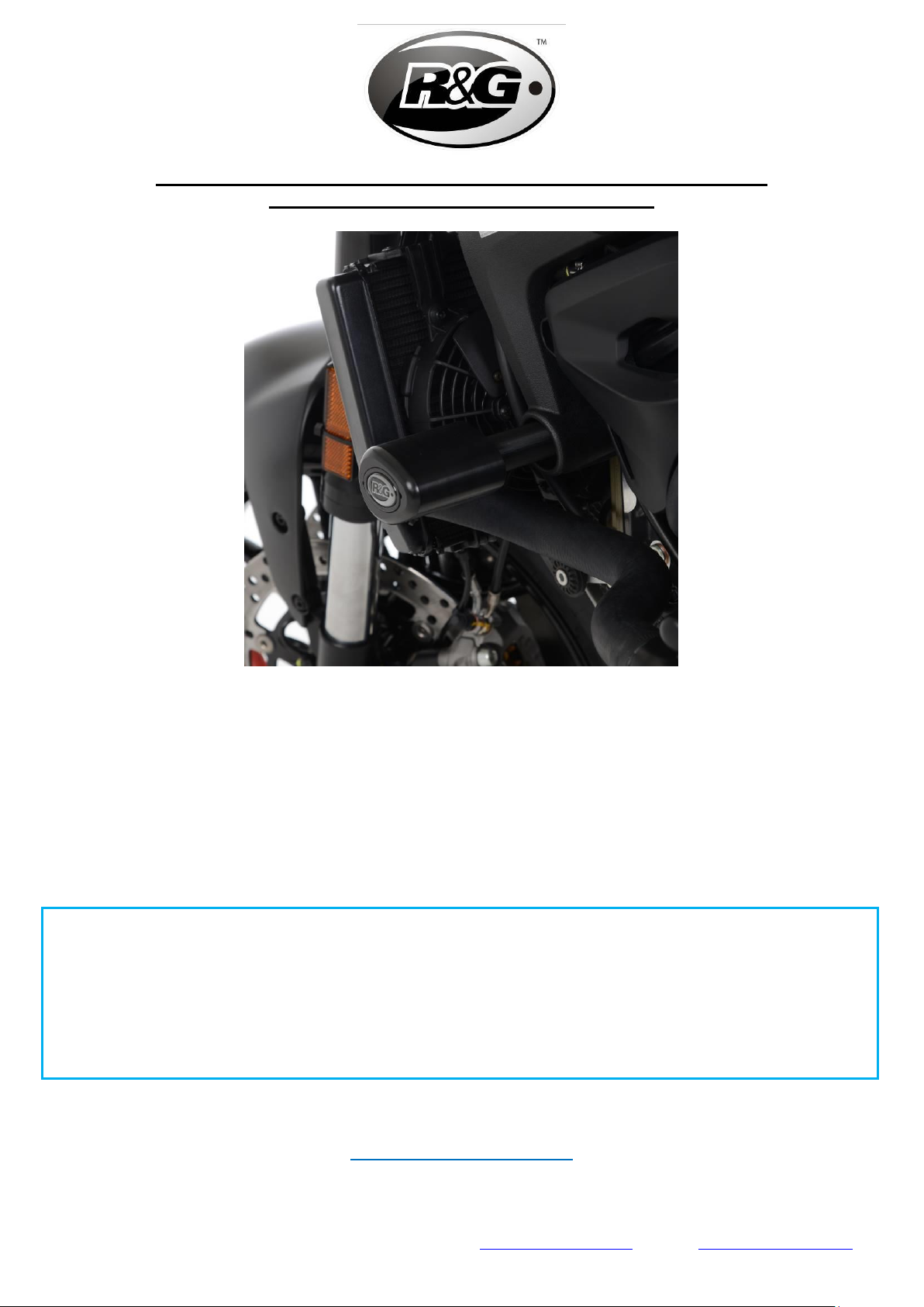
•Retirez le boulon de fixation du moteur d’origine illustré sur la photo 1.
•Installez l'ensemble protection et boulon préalablement préparé dans le support du moteur.
Vissez la barre de moteur M12 et l'écrou dans le filetage qui maintiendra l'ensemble en position.
REMARQUE : Pour éviter un filetage croisé, appliquez une pression vers l'avant sur le boulon et
tournez dans le sens inverse des aiguilles d'une montre jusqu'à ce qu'un clic se fasse entendre,
puis commencez à tourner dans le sens des aiguilles d'une montre et serrez.
•À l'aide d'une clé dynamométrique équipée d'une clé Douille 19mm, serrez la barre du moteur
et l'écrou à 45 Nm. Vous devrez peut-être maintenir la protection en position pour l'empêcher
de tourner pendant le serrage du boulon.
•Répétez le même processus de l'autre côté, en vous assurant que la protection soit orientée
dans le bon sens. Notez que le côté gauche est plus long que le côté droit afin que les bobines
soient positionnées de manière égale sur la moto.
•Une fois terminé, vérifiez les réglages de couple et la position/orientation des protections, puis
poussez les capuchons de protection (ARTICLE2) en place, puis retirez le cric.
ISSUE 1 - 09/09/2021 (WW)
ISSUE 2 –17/09/2021 –8MM ALLEN TOOL CHANGED TO 19MM SOCKET –(WW)
ISSUE 3 –28/09/2021 –NYLOC ERROR CORRECTED –(WW)
CONSUMER NOTICE
The catalogue description and any exhibition of samples are only broad indications of the Products and R&G may make design changes which do
not diminish their performance or visual appeal and supplying them in such state shall conform to the order. The Buyer acknowledges no
representation or warranty (other than as to title) has been given or will apply to the Products other than those in R&G’s order or confirmation and
the Buyer confirms it has chosen the Products as being of merchantable quality and suitable for its particular purposes. Where R&G fits the
Products or undertakes other services it shall exercise reasonable skill and care and rectify any fault free of charge unless the workmanship has
been disturbed. The Buyer is responsible for ensuring that the warranty on the motorcycle is not affected by the fitting of the Products. On return
of any defective Products R&G shall at its option either supply a replacement or refund the purchase money but shall not be liable if the Products
have been modified or used or maintained otherwise than in accordance with R&G’s or manufacturer’s instructions and good engineering practice or
if the defect arises from accident or neglect. Other than identified above and subject to R&G not limiting its liability for causing death and personal
injury, it shall not be liable for indirect or consequential loss and otherwise its liability shall be limited to the amounts paid by the Buyer for the
Products or the fitting or service concerned. These terms do not affect the Buyer’s statutory rights.
R&G RACING RETURNS POLICY (NON-FAULTY GOODS)
Returns must be pre-authorised (if not pre-authorised the return will be rejected). Goods may only be returned direct to us if they were purchased
direct from us (customer must prove if necessary). Otherwise to be returned to original vendor. Goods must be in re-sellable condition, in the
opinion of R&G Racing. All returns are subject to a 25% restocking and handling fee (25% of the gross value exc. P&P –at the prevailing price at
time of purchase). The customer must pay any and all carriage charges. No returns of discontinued products, unless within 14 days of purchase.
This policy does not affect your statutory rights and does not refer to faulty goods.

Page 9of 12 CP0526
R&G Racing
Unit 1, Shelley’s Lane, East Worldham, Alton, Hampshire, GU34 3AQ
Tel: +44 (0)1420 89007 Fax: +44 (0)1420 87301 www.rg-racing.com Email: info@rg-racing.com
MONTAGEANLEITUNG FÜR CP0526 AERO STURZPADS
DUCATI MONSTER 950 (PLUS) 2021-
ALLE KIT-TEILE SIND AUF DEN NACHFOLGENDEN SEITEN ABGEBILDET UND GEKENNZEICHNET.
DIE ABGEBILDETEN TEILE DIENEN LEDIGLICH ZUR ERKLÄRUNG.
ÜBERPRÜFEN SIE ZUERST,DASS ALLE TEILE VORHANDEN SIND.
LESEN SIE DIE MONTAGEANLEITUNG KOMPLETT DURCH,BEVOR SIE ANFANGEN.
WENN SIE BEI DER MONTAGE DIESES PRODUKTES UNSICHER SIND, BITTE EINEN
UNSERER HÄNDLER KONTAKTIEREN ODER DAS KIT VON EINEM QUALIFIZIERTEN
ZWEIRAD-MECHANIKER MONTIEREN LASSEN.
DIE VERPACKUNG DER TEILE STELLT NICHT DIE REIHENFOLGE DER MONTAGE DAR.
HINWEIS FÜR KITS MIT PLASTIKUNTERLEGSCHEIBEN AN DEN SCHRAUBEN –
DIESE PLASTIK-UNTERLEGSCHEIBEN WERDEN NICHT FÜR DEN EINBAU BENÖTIGT
EINE DIGITALE VERSION DIESER MONTAGEANLEITUNG KANN AUF
FOLGENDER SEITE HERUNTERGELADEN WERDEN:
WWW.RG-RACING.COM

Page 10 of 12 CP0526
R&G Racing
Unit 1, Shelley’s Lane, East Worldham, Alton, Hampshire, GU34 3AQ
Tel: +44 (0)1420 89007 Fax: +44 (0)1420 87301 www.rg-racing.com Email: info@rg-racing.com
SIE BENÖTIGEN FOLGENDES WERKZEUG
•STECKSCHLÜSSELSATZ INKL. 15mm und
17mm STECKSCHLÜSSEL
•DREHMOMENTSCHLÜSSEL (BIS 50Nm)
•HEBER ODER MONTAGESTÄNDER
ALLGEM.ANZUGSDREHMOMENT
M4 SCHRAUBE = 8Nm
M5 SCHRAUBE = 12Nm
M6 SCHRAUBE = 15Nm
M8 SCHRAUBE = 20Nm
M10 SCHRAUBE = 40Nm
M12 SCHRAUBE = 40Nm
LIEFERUMFANG
ARTIKEL
NR.
BESCHREIBUNG
MENGE
ARTIKEL 1
B0061 - AERO STURZPADS
2
ARTIKEL 2
BC0002 –STURZPAD-SCHUTZKAPPEN (BEIDE SEITEN)
2
ARTIKEL 3
S1357 –DISTANZHALTER STURZPAD RECHTE SEITE
1
ARTIKEL 4
S1358 - DISTANZHALTER STURZPAD LINKE SEITE
1
ARTIKEL 5
EB105 220MM VERBINDUNGSSTANGE (LINKE SEITE)
1
ARTIKEL 6
EB106 180MM VERBINDUNGSSTANGE (RECHTE SEITE)
1
ARTIKEL 7
M12 SELBSTSICHERNDE MUTTER
2
ARTIKEL 8
LW0001 ZAHNSCHEIBE
2
ARTIKEL 9
M12 UNTERLEGSCHEIBE
2
AERO-STURZPAD ORIENTIERUNG
MOTORRAD VORNE
MOTORRAD HINTEN

Page 11 of 12 CP0526
R&G Racing
Unit 1, Shelley’s Lane, East Worldham, Alton, Hampshire, GU34 3AQ
Tel: +44 (0)1420 89007 Fax: +44 (0)1420 87301 www.rg-racing.com Email: info@rg-racing.com
LINKE & RECHTE SEITE EXPLOSIONSZEICHNUNG - ZUSAMMENBAU
MONTAGE ABBILDUNGEN
Abbildung 1
Abbildung 2
Abbildung 3
1
2
3
4
5
6
7
8
9

Page 12 of 12 CP0526
R&G Racing
Unit 1, Shelley’s Lane, East Worldham, Alton, Hampshire, GU34 3AQ
Tel: +44 (0)1420 89007 Fax: +44 (0)1420 87301 www.rg-racing.com Email: info@rg-racing.com
MONTAGEANLEITUNG
Bevor Sie die Schrauben für den Motor entfernen, stellen Sie sicher, dass das Motorrad aufrecht steht
und der Motor mit einem geeigneten Ständer/Heber unterhalb der Ölwanne gestützt wird. Dies
verhindert, dass der Motor sich bei der Entfernung von Motorschrauben bewegt. WÄHREND DER
INSTALLATION DÜRFEN DIE SCHRAUBEN FÜR DEN MOTOR NUR EINZELN UND NIE
GLEICHZEITIG ENTFERNT WERDEN.
VORBEREITUNG:
•Einen passenden Motorradheber oder Montageständer mittig unter den Motor stellen mit einem
Stuck Holz oder Kunststoff zwischen dem Motor und dem Ständer.
•Etwas Druck an der Unterseite des Motors anwenden, um den Motor während der Montage zu
stützen
Die Sturzpads zusammenbauen, bevor Sie die Motorschrauben entfernen, sodass der
Motor nur für eine kurze Zeit nicht vollständig gestützt ist.
•Die selbstsichernden Muttern (ARTIKEL 7) mit 20mm Gewinde am jeweiligen Ende der zwei
Verbindungsstangen (ARTIKEL 5/6) anbringen. Sie können einen 10mm Schraubenschlüssel
benutzen, um die Verbindungsstange dabei zu halten.
•Die Verbindungsstangen jeweils mit Mutter und Unterlegscheiben (ARTIKEL 1) gefolgt von den
Distanzhaltern für die Sturzpads (ARTIKEL 3/4) in die Aero Sturzpads einsetzen.
MONTAGE:
•Entfernen Sie die Motorschraube wie in Abbildung 1 abgebildet.
•Die Sturzpad-Einheit, die Sie vorher zusammengebaut haben, in die Montagehalterung
einsetzen. Die M12 Verbindungsstange und Mutter in das Einschraubgewinde eindrehen, welche
die Einheit festhalten wird.
HINWEIS: Um zu vermeiden, dass die Schraube sich verkantet, etwas Druck
anwenden und die Schraube entgegen dem Uhrzeiger drehen bis Sie einen Klick
hören, dann die Schraube rechtsherum drehen und befestigen.
•Benutzen Sie einen Drehmomentschlüssel mit einem 19mm Sockel montiert, um die
Verbindungsstange und Mutter mit 45 NM zu befestigen. Eventuell müssen Sie das Sturzpad in
Position halten, um zu verhindern, dass es sich während des Festziehens dreht.
•Wiederholen Sie diese Schritte an der anderen Seite des Motorrades und stellen Sie sicher, dass
die Sturzpads ordnungsgemäß ausgerichtet sind. Bitte beachten Sie, dass die linke Seite länger
ist als die rechte Seite, sodass die Sturzpads gleich positioniert sind am Motorrad.
•Wenn alles montiert ist, überprüfen Sie erneut die Drehmoment-Einstellungen und die
Position/Orientierung der Sturzpads. Die Sturzpad-Kappen (ARTIKEL 2) anbringen und
anschließend den Heber entfernen.
AUSGABE 1 - 09/09/2021 (WW)
CONSUMER NOTICE
The catalogue description and any exhibition of samples are only broad indications of the Products and R&G may make design changes which do
not diminish their performance or visual appeal and supplying them in such state shall conform to the order. The Buyer acknowledges no
representation or warranty (other than as to title) has been given or will apply to the Products other than those in R&G’s order or confirmation and
the Buyer confirms it has chosen the Products as being of merchantable quality and suitable for its particular purposes. Where R&G fits the
Products or undertakes other services it shall exercise reasonable skill and care and rectify any fault free of charge unless the workmanship has
been disturbed. The Buyer is responsible for ensuring that the warranty on the motorcycle is not affected by the fitting of the Products. On return
of any defective Products R&G shall at its option either supply a replacement or refund the purchase money but shall not be liable if the Products
have been modified or used or maintained otherwise than in accordance with R&G’s or manufacturer’s instructions and good engineering practice or
if the defect arises from accident or neglect. Other than identified above and subject to R&G not limiting its liability for causing death and personal
injury, it shall not be liable for indirect or consequential loss and otherwise its liability shall be limited to the amounts paid by the Buyer for the
Products or the fitting or service concerned. These terms do not affect the Buyer’s statutory rights.
R&G RACING RETURNS POLICY (NON-FAULTY GOODS)
Returns must be pre-authorised (if not pre-authorised the return will be rejected). Goods may only be returned direct to us if they were purchased
direct from us (customer must prove if necessary). Otherwise to be returned to original vendor. Goods must be in re-sellable condition, in the
opinion of R&G Racing. All returns are subject to a 25% restocking and handling fee (25% of the gross value exc. P&P –at the prevailing price at
time of purchase). The customer must pay any and all carriage charges. No returns of discontinued products, unless within 14 days of purchase.
This policy does not affect your statutory rights and does not refer to faulty goods.
Table of contents
Other R&G Motorcycle Accessories manuals