R&G RSET02BK User manual

R&G Racing
Unit 1, Shelley’s Lane, East Worldham, Alton, Hampshire, GU34 3AQ
Tel: +44 (0)1420 89007 Fax: +44 (0)1420 87301 www.rg-racing.com Email: info@rg-racing.com
Page | 1
FITTING INSTRUCTIONS FOR RSET02BK ADJUSTABLE REAR SET
HONDA CBR1000RR 2008-2011
THIS KIT CONTAINS THE ITEMS PICTURED AND LABELLED BELOW.
DO NOT PROCEED UNTIL YOU ARE SURE ALL PARTS ARE PRESENT.
Please note that the way the kit is packed does not necessarily represent the way of
mounting to the bike
THE PARTS SHOWN MAY BE REPRESENTATIVE ONLY (FOR CLARITY OF INSTRUCTIONS ONLY)
LEFT HAND/GEAR SHIFT SIDE
5
3
2
1
4
5
5
5

R&G Racing
Unit 1, Shelley’s Lane, East Worldham, Alton, Hampshire, GU34 3AQ
Tel: +44 (0)1420 89007 Fax: +44 (0)1420 87301 www.rg-racing.com Email: info@rg-racing.com
Page | 2
THIS KIT CONTAINS THE ITEMS PICTURED AND LABELLED BELOW.
DO NOT PROCEED UNTIL YOU ARE SURE ALL PARTS ARE PRESENT.
RIGHT HAND/BRAKE SIDE
4
9
6
5
8
15
17
7
16
45
10
11
8
10
9
9
13
12
14

R&G Racing
Unit 1, Shelley’s Lane, East Worldham, Alton, Hampshire, GU34 3AQ
Tel: +44 (0)1420 89007 Fax: +44 (0)1420 87301 www.rg-racing.com Email: info@rg-racing.com
Page | 3
LEGEND
ITEM 1= LEFT HAND SIDE ASSEMBLY (x1).
ITEM 2= GEAR SHIFT LEVER (x1).
ITEM 3= GEAR SHAFT ROD (x1).
ITEM 4= GEAR BOX CONNECTOR (ANGLED) (x1).
ITEM 5= M8x16mm LONG BUTTON HEAD BOLTS (4x EACH SIDE) (x8).
ITEM 6= M8 NUT (x1).
ITEM 7= RIGHT HAND SIDE MOUNTING PLATE (x1).
ITEM 8= RESERVOIR MOUNTING BRACKET (x1).
ITEM 9= M6 NYLOC NUTS (x3).
ITEM 10= M6x25mm LONG BUTTON HEAD BOLTS (x2).
ITEM 11= RIGHT HAND SIDE SUB PLATE (x1).
ITEM 12= RESERVOIR MOUNTING BRACKET SPACER (10mm LONG) (x1).
ITEM 13= M6x40mm LONG BUTTON HEAD BOLT (x1).
ITEM 14= M8x30mm LONG BUTTON HEAD BOLT (x1).
ITEM 15= PACKET OF BULLET CONNECTORS FOR BRAKE LIGHT SWITCH (CON 4) (x1).
ITEM 16= ALUMINIUM SEALING WASHERS (x2).
ITEM 17= BRAKE LIGHT SENSOR SWITCH (x1).
TOOLS REQUIRED
8, 10, 12 AND 24mm OPEN ENDED SPANNERS.
19 AND 24mm SOCKET AND WRENCH.
ELECTRICAL/CRIMPING PLIERS.
TORQUE WRENCH UP TO 80Nm.
METRIC ALLEN KEY SET UP TO 8mm A/F.
TORQUE SETTINGS
M4 BOLT = 8Nm
M5 BOLT = 12Nm
M6 BOLT = 15Nm
M8 BOLT = 20Nm
M10 BOLT = 25Nm
GEAR LEVER=80Nm
PICTURE 1 PICTURE 2

R&G Racing
Unit 1, Shelley’s Lane, East Worldham, Alton, Hampshire, GU34 3AQ
Tel: +44 (0)1420 89007 Fax: +44 (0)1420 87301 www.rg-racing.com Email: info@rg-racing.com
Page | 5
GEAR SHIFT SIDE
Remove the original gear shift lever mounting bolt shown in picture 1.
Remove the clamping bolt for the gear box connector as shown in picture 2.
Remove the gear box connector and remove the gear selector lever assembly.
Remove the two bolts and the original left hand footrest (shown in picture 3).
Fit the new left hand side footrest using the two M8x16mm long button head bolts as shown in
picture 7, using the two bolts arrowed in picture 7 adjust for comfort and position and tighten
bolts.
Undo and remove the engine mount bolt arrowed in picture 4.
Fit the gear lever pivot/mounting bracket in place of the nut just removed and tighten to 80Nm as
shown in picture 6.
Select the required gear shift pattern, either normal or race. Fit the gear shift rod ball-joint to holes
labelled ‘A’ for race pattern (1up—5down) or holes marked ‘B’ for normal pattern (1down—5up)
as shown in picture 6.
Fit the gear shift rod to the lower ball-joint just fitted (will only fit one way as threads in either end
are opposite handed; do not tighten at this stage (please ensure thread has a minimum of 8mm
engagement).
Remove the clamping bolt from the new gear box connector.
Fit the new gear box connector to the gear shift rod; do not tighten at this stage (please ensure
thread has a minimum of 8mm engagement).
Fit the new gear box connector to the splined shaft as shown in picture 5 (this must be mounted at
right angle as shown), when satisfied with position, fit and tighten the clamping bolt.
Tighten all bolts and lock-nuts.
PICTURE 8

R&G Racing
Unit 1, Shelley’s Lane, East Worldham, Alton, Hampshire, GU34 3AQ
Tel: +44 (0)1420 89007 Fax: +44 (0)1420 87301 www.rg-racing.com Email: info@rg-racing.com
Page | 6
PICTURE 9 PICTURE 10
PICTURE 11 PICTURE 12
PICTURE 13 PICTURE 14
BRAKE SIDE
Remove the two bolts holding the heel-guard and master cylinder in position as arrowed in picture
8.
Remove the two bolts holding the original foot-rest in position as arrowed in picture 8.
Undo and remove the bolt holding the reservoir.
Undo and remove the exhaust mounting bolt as shown in picture 8.
The whole assembly can now be gently eased away from bike to allow access to the bolt holding
the exhaust shield in position as shown in picture 9.
Remove the exhaust heat shield.
Unhook and remove the brake light sensor switch as shown in picture 10.

R&G Racing
Unit 1, Shelley’s Lane, East Worldham, Alton, Hampshire, GU34 3AQ
Tel: +44 (0)1420 89007 Fax: +44 (0)1420 87301 www.rg-racing.com Email: info@rg-racing.com
Page | 7
Undo and remove the clevis pin that holds the brake pressure shaft from the original foot-rest.
Remove the original mount from the master cylinder pressure shaft.
Remove the original foot-rest from bike.
Fit the new lower ball-joint to the master cylinder pressure shaft as shown in picture 11, PLEASE
LEAVE BALL-JOINT AND LOCK NUT LOOSE AT THIS STAGE.
Refit the exhaust mounting bolt as original.
Use the two new M8 bolts to mount and secure the new foot-rest assembly as arrowed in picture
12.
Use the two new M6 bolts and nuts to secure the master cylinder to the adaptor plate and the
reservoir adaptor plate as shown in picture 12.
Secure the brake reservoir as shown in picture 15.
Adjust the new lower ball joint so the action of the master cylinder pressure shaft is directly in line
with master cylinder as shown in picture 14. PLEASE NOTE FAILURE TO DO THIS MAY
RESULT IN BRAKE FAILURE AND/OR JAMMING OF BRAKES. Use the lock nut to lock
in position.
Adjust for comfort and position using the sub plate and two bolts arrowed in picture 13.
PICTURE 15
BRAKE LIGHT SENSOR SWITCH
Remove the bolt holding the banjo fitting to end of the master cylinder and replace the bolt with
the brake light sensor switch (item 17) using the aluminium sealing washers supplied (item 16) as
arrowed in picture 15. PLEASE NOTE YOU WILL HAVE TO BLEED THE BRAKING
SYSTEM.
We recommend cutting the original wiring and using the bullet connectors (item 15) to connect the
brake light sensor switch wires to the original wiring.
Please check operation of brakes and brake light before riding.

R&G Racing
Unit 1, Shelley’s Lane, East Worldham, Alton, Hampshire, GU34 3AQ
Tel: +44 (0)1420 89007 Fax: +44 (0)1420 87301 www.rg-racing.com Email: info@rg-racing.com
Page | 8
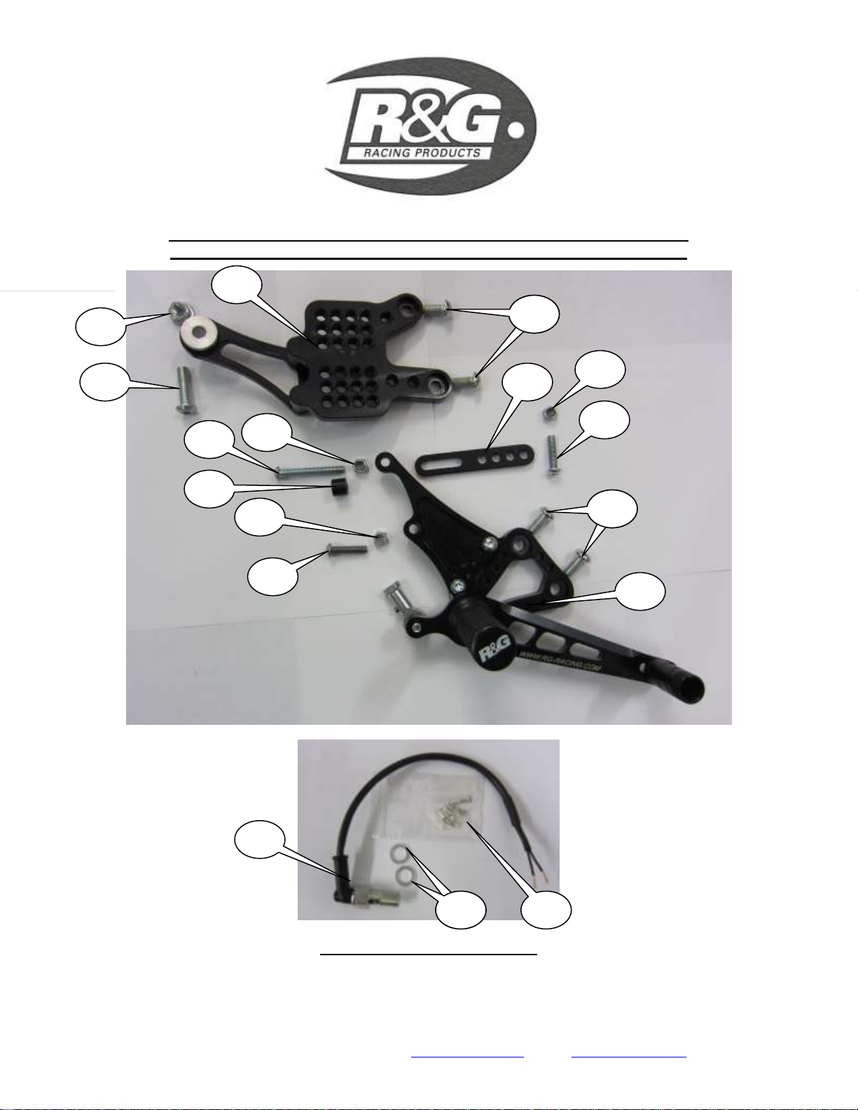
Because of the complexity and inherent dangers involved in undertaking any work
involving the braking system we strongly recommend a qualified mechanic fits/or checks
after the fitting of this product.
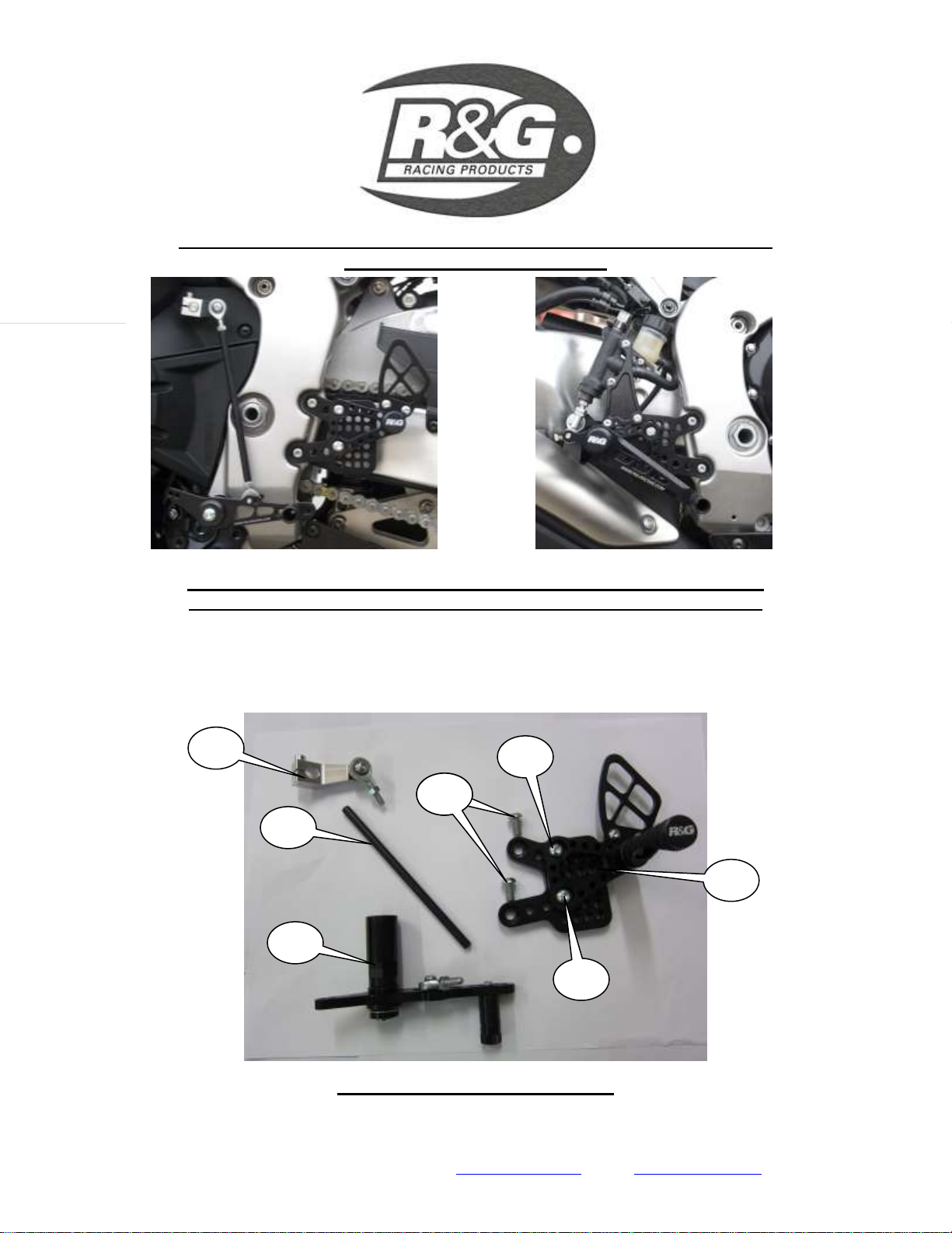
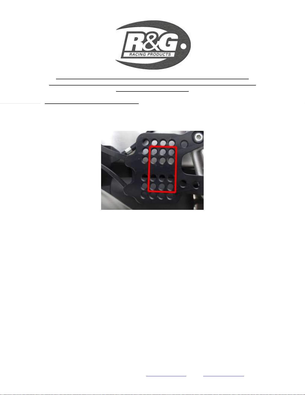
SPECIAL NOTES FOR ABS MODELS
ON ABS MODELS THE ONLY AVAILABLE ADJUSTMENT POSITIONS ARE WITHIN THE AREA
MARKED ON THE PICTURE BELOW. ALSO ON ABS MODELS WE RECOMMEND THAT A
HONDA DEALER CARRY OUT THE FITMENT AS IT IS QUITE DIFFICULT TO BLEED THE
SYSTEM.
ISSUE 1 24/10/2011 (NSY)
CONSUMER NOTICE
The catalogue description and any exhibition of samples are only broad indications of the Products and R&G may make design
changes which do not diminish their performance or visual appeal and supplying them in such state shall conform to the order. The
Buyer acknowledges no representation or warranty (other than as to title) has been given or will apply to the Products other than those
in R&G’s order or confirmation and the Buyer confirms it has chosen the Products as being of merchantable quality and suitable for
its particular purposes. Where R&G fits the Products or undertakes other services it shall exercise reasonable skill and care and rectify
any fault free of charge unless the workmanship has been disturbed. The Buyer is responsible for ensuring that the warranty on the
motorcycle is not affected by the fitting of the Products. On return of any defective Products R&G shall at its option either supply a
replacement or refund the purchase money but shall not be liable if the Products have been modified or used or maintained otherwise
than in accordance with R&G’s or manufacturer’s instructions and good engineering practice or if the defect arises from accident or
neglect. Other than identified above and subject to R&G not limiting its liability for causing death and personal injury, it shall not be
liable for indirect or consequential loss and otherwise its liability shall be limited to the amounts paid by the Buyer for the Products or
the fitting or service concerned. These terms do not affect the Buyer’s statutory rights.
R&G RACING RETURNS POLICY (NON-FAULTY GOODS)
Returns must be pre-authorised (if not pre-authorised the return will be rejected). Goods may only be returned direct to us if they were
purchased direct from us (customer must prove if necessary). Otherwise to be returned to original vendor. Goods must be in re-
sellable condition, in the opinion of R&G Racing. All returns are subject to a 25% restocking and handling fee (25% of the gross value
exc. P&P –at the prevailing price at time of purchase). The customer must pay any and all carriage charges. No returns of
discontinued products, unless within 14 days of purchase. This policy does not affect your statutory rights and does not refer to faulty
goods.

R&G Racing
Unit 1, Shelley’s Lane, East Worldham, Alton, Hampshire, GU34 3AQ
Tel: +44 (0)1420 89007 Fax: +44 (0)1420 87301 www.rg-racing.com Email: info@rg-racing.com
Page | 9
INSTRUCTIONS DE MONTAGE POUR RSET02BK
TRAIN ARRIERE AJUSTABLE
HONDA CBR1000RR 2008-2011
Verifier le contenu de la boite avant de deballer les pieces
La facon dont le kit est emballé ne représente pas nécessairement la façon de le monter sur la
moto
Les parties représentées peuvent parfois être uniquement représentatives
(Pour la clarté des explications)
5
3
2
1
4
5
5
5

R&G Racing
Unit 1, Shelley’s Lane, East Worldham, Alton, Hampshire, GU34 3AQ
Tel: +44 (0)1420 89007 Fax: +44 (0)1420 87301 www.rg-racing.com Email: info@rg-racing.com
Page | 11
COTE DROIT / COTE FREIN
LEGENDE
Image 2 = Levier de vitesses (x1).
Image 3 = Réducteur Levier de vitesses (x1).
Image 4 = Connecteur boîte de vitesses (x1).
Image 5 = M8x16mm Longs boulons à tête ronde (4x chaque coté) (x8).
Image 6 = écrou M8 (x1).
Image 7 = Plaque de montage coté droit (x1).
Image 8 = Réservoir support de montage (x1).
Image 9 = M6 écrous nyloc (x3).
Image 10 = M6x25mm Longs boulons à tête ronde (x2).
Image 11 = Sous plaque coté droit (x1).
Image 12 = Entretoise pour support (10 mm de long) (x1).
Image 13 = M6x40mm Boulons (x1).
Image 14 = M8x30mm Boulons à tête ronde (x1).
Image 15 Connecteurs pour interrupteur feux-stop (CON 4) (x1).
Image 16 = rondelles d'étanchéité en aluminium (x2).
Image 17 = Interrupteur de freins (x1).
Outils requis
8, 10, 12 AND 24mm Clés Ouvert Fermé.
19 AND 24mm Prise et clé
Pince à sertir
Clé dynamométrique réglée à 80Nm.
Clé Allen métrique réglée à 8mm A/F.
Réglages de couple
Boulon M4 = 8Nm
Boulon M5 = 12Nm
Boulon M6 = 15Nm
Boulon M8 = 20Nm
Boulon M10 = 25Nm
Levier de vitesses = 80Nm

R&G Racing
Unit 1, Shelley’s Lane, East Worldham, Alton, Hampshire, GU34 3AQ
Tel: +44 (0)1420 89007 Fax: +44 (0)1420 87301 www.rg-racing.com Email: info@rg-racing.com
Page | 13
Image 7
COTE CHANGEMENT DE VITESSE
Retirez le boulon du levier de vitesses d’origine comme indiqué sur l'image 1.
Retirez les vis de serrage du connecteur boîte de vitesse comme le montre la photo 2.
Retirer le connecteur boîte et le sélecteur de vitesses.
Retirez les deux boulons et le repose-pied d’origine à gauche (image 3).
Monter les nouveaux repose-pieds côté gauche en utilisant les deux boulons M8x16mm
comme indiqué dans l'image 7, en ajustant pour un confort optimal du motard.
Dévisser et retirer le boulon de support (image 4).
Monter le levier de vitesses pivot / support de fixation à la place de l'écrou qui vient
d’être enlevé et serrer à 80nm comme indiqué sur l'image 6.
Sélectionnez le modèle de matériel nécessaire : « normale » ou « race ». Monter la
rotule de tige du levier de vitesses étiquetée «A» pour modèle race (1 en haut -5 en
dessous) ou trous marqués «B» pour le modèle normal (1 en dessous –5 au dessus)
comme indiqué sur l'image 6.
Monter la tige de levier de vitesse à la plus petite rotul, ne serrez pas à ce stade (s'il
vous plaît assurez vous que le fil ait un minimum d'engagement de 8mm).
Retirez le boulon de serrage du connecteur de la nouvelle boîte de vitesses.
Monter le connecteur à la nouvelle à la tige de levier de vitesse, ne pas serrer à ce stade
(s'il vous plaît assurez vous que le fil ait un minimum d'engagement 8mm).
Monter les connecteurs de la nouvelle boîte de vitesses, comme indiqué dans l'image 5
(ce doit être monté à angle droit, comme indiqué). Ajustez ensuite afin de trouver la
position idéale et serrer.
Resserrer tous les boulons et écrous.

R&G Racing
Unit 1, Shelley’s Lane, East Worldham, Alton, Hampshire, GU34 3AQ
Tel: +44 (0)1420 89007 Fax: +44 (0)1420 87301 www.rg-racing.com Email: info@rg-racing.com
Page | 15
Image 11 Image 12
IMAGE 13 IMAGE 14
Coté frein
Retirez les deux boulons de fixation du vérin du garde talon (image 8).
Retirez les deux boulons de fixation du repose-pied original en position (image 8).
Enlever le boulon de fixation du réservoir.
Dévisser et retirer le boulon de fixation du pot d'échappement (image 8).
L'ensemble peut maintenant être extrait délicatement de la moto, pour permettre
l'accès au boulon qui tient le bouclier d'échappement en position (image 9).
Supprimer le bouclier thermique d'échappement.
Débranchez et retirez l'interrupteur de feu stop comme le montre l'image 10.
Dévisser et retirer l'axe de chape qui détient l'arbre pression de freinage du repose-pied
original.
Retirer le support original de l'arbre de pression du maître-cylindre.
Retirez le repose pieds original de la moto.

R&G Racing
Unit 1, Shelley’s Lane, East Worldham, Alton, Hampshire, GU34 3AQ
Tel: +44 (0)1420 89007 Fax: +44 (0)1420 87301 www.rg-racing.com Email: info@rg-racing.com
Page | 16
Monter la nouvelle rotule inférieure à l'arbre de pression du maître-cylindre comme le
montre l’image 11, Ne rien bloquer à ce stade.
Remonter le boulon de fixation d'échappement original.
Montez les deux nouveaux boulons M8 et sécuriser les nouveaux repose-pieds comme
sur l'image 12.
Utilisez les deux nouveaux boulons M6 et les écrous pour fixer le maître cylindre à la
plaque de l'adaptateur, comme indiqué dans l'image 12.
Fixe r le réservoir de liquide de frein comme montré dans l'image 15.
Ajustez la nouvelle rotule inférieure de sorte que l'action de l'arbre de pression du
maître-cylindre soit directement en ligne avec le maître-cylindre comme indiqué sur
l'image 14.
NOTE : Ne pas effectuer correctement ce montage, niles vérifications destinées à
assurer une sécurité optimale peuvent provoquer la défaillance du frein ou son
blocage. Utilisez l'écrou de blocage pour verrouiller en position.
Ajustez la position en utilisant la sous plaque sous et deux boulons (image 13).
Image 15
Contact de feu stop
• Retirez le boulon qui tient le banjo à l’extrémité du maître-cylindre et remplacer le boulon
avec le commutateur de capteur de lumière de frein (point 17) en utilisant les rondelles
d'étanchéité en aluminium fournies (point 16) comme indiqué sur l'image 15.

R&G Racing
Unit 1, Shelley’s Lane, East Worldham, Alton, Hampshire, GU34 3AQ
Tel: +44 (0)1420 89007 Fax: +44 (0)1420 87301 www.rg-racing.com Email: info@rg-racing.com
Page | 17
NOTE : Le système de freinage devra être purgé.
• Nous vous recommandons de couper le câblage d'origine en utilisant les connecteurs de balle
(point 15) pour connecter les câbles de d’interrupteur de freins au câblage d'origine.
•S'il vous plaît vérifier le bon fonctionnement des freins et des feux stop avant de rouler.
DU FAIT DE LA COMPLEXITE ET DES RISQUES INHERENTS A LA MODIFICATION DE CERTAINS
ELEMENTS DE LA MOTO IMPLIQUANT LE SYSTEME DE FREINAGE, NOUS RECOMMANDONS
VIVEMENT DE FAIRE CONTROLER LE MONTAGE PAR UN MECANICIEN QUALIFIE.
NOTE : Modèle ABS
Sur les modèles ABS, les positions de réglage sont uniquement disponibles dans la zone
marquée sur l’image ci dessous. Aussi, sur les modèles ABS, nous recommandons que le
montage soit effectué par un concessionnaire Honda, du fait également de la difficulté de la
purge du système de frein.
ISSUE 1 24/10/2011 (NSY)
CONSUMER NOTICE
The catalogue description and any exhibition of samples are only broad indications of the Products and R&G may make design
changes which do not diminish their performance or visual appeal and supplying them in such state shall conform to the order. The
Buyer acknowledges no representation or warranty (other than as to title) has been given or will apply to the Products other than those
in R&G’s order or confirmation and the Buyer confirms it has chosen the Products as being of merchantable quality and suitable for
its particular purposes. Where R&G fits the Products or undertakes other services it shall exercise reasonable skill and care and rectify
any fault free of charge unless the workmanship has been disturbed. The Buyer is responsible for ensuring that the warranty on the
motorcycle is not affected by the fitting of the Products. On return of any defective Products R&G shall at its option either supply a
replacement or refund the purchase money but shall not be liable if the Products have been modified or used or maintained otherwise
than in accordance with R&G’s or manufacturer’s instructions and good engineering practice or if the defect arises from accident or
neglect. Other than identified above and subject to R&G not limiting its liability for causing death and personal injury, it shall not be
liable for indirect or consequential loss and otherwise its liability shall be limited to the amounts paid by the Buyer for the Products or
the fitting or service concerned. These terms do not affect the Buyer’s statutory rights.
R&G RACING RETURNS POLICY (NON-FAULTY GOODS)
Returns must be pre-authorised (if not pre-authorised the return will be rejected). Goods may only be returned direct to us if they were
purchased direct from us (customer must prove if necessary). Otherwise to be returned to original vendor. Goods must be in re-
sellable condition, in the opinion of R&G Racing. All returns are subject to a 25% restocking and handling fee (25% of the gross value
exc. P&P –at the prevailing price at time of purchase). The customer must pay any and all carriage charges. No returns of
discontinued products, unless within 14 days of purchase. This policy does not affect your statutory rights and does not refer to faulty
goods.
Table of contents
Languages:
Other R&G Motorcycle Accessories manuals