R&G RAP0009 User manual

R&G Racing
Unit 1, Shelleys Lane, East Worldham, Alton, Hampshire GU34 3AQ.
Tel: +44 (0)1420 89007 Fax +44 (0)1420 87301 www.rg-racing.com Email: info@rg-racing.com
PAGE 1 OF 9 RAP0009
Picture A
FITTING INSTRUCTIONS FOR RAP0009 REAR INDICATOR ADAPTORS
KTM 1290 SUPERDUKE GT 2019-
DIGITAL COPIES OF THESE INSTRUCTIONS ARE AVAILABLE FROM:
WWW.RG-RACING.COM
THIS KIT CONTAINS THE ITEMS PICTURED AND LABELLED OVER PAGE.
SOME PARTS MAY BE SHOWN FOR CLARITY OF INSTRUCTIONS ONLY.
DO NOT PROCEED UNTIL YOU ARE SURE ALL PARTS ARE PRESENT.
PLEASE READ ALL INSTRUCTIONS BEFORE PROCEEDING.
IF IN ANY DOUBT WHEN FITTING OUR PRODUCTS, CONSULT ONE OF OUR DEALERS
OR HAVE FITTED BY A QUALIFIED TECHNICIAN.
PLEASE NOTE THAT THE WAY THE KIT IS PACKED DOES NOT NECESSARILY REPRESENT THE WAY OF
MOUNTING TO THE BIKE.
IN THE EVENT OF RUBBER WASHERS BEING USED TO HOLD COMPONENTS ONTO BOLTS,
THESE RUBBER WASHERS CAN BE THROWN AWAY.

R&G Racing
Unit 1, Shelleys Lane, East Worldham, Alton, Hampshire GU34 3AQ.
Tel: +44 (0)1420 89007 Fax +44 (0)1420 87301 www.rg-racing.com Email: info@rg-racing.com
PAGE 2 OF 9 RAP0009
TOOLS REQUIRED
• 13mm Spanner
• T15 Torx Tool
• 10mm Socket and Wrench
GENERAL TORQUE SETTINGS
M4 BOLT = 8Nm
M5 BOLT = 12Nm
M6 BOLT = 15Nm
M8 BOLT = 20Nm
M10 BOLT = 40Nm
M12 BOLT = 40Nm
LEGEND
ITEM
No.
DESCRIPTION QTY
ITEM 1 CON0014 INDICATOR CONNECTOR 2
ITEM 2 RB050-20-00FG RUBBER BUNG 2
Picture 1 Picture 2
Picture 3 Picture 4

R&G Racing
Unit 1, Shelleys Lane, East Worldham, Alton, Hampshire GU34 3AQ.
Tel: +44 (0)1420 89007 Fax +44 (0)1420 87301 www.rg-racing.com Email: info@rg-racing.com
PAGE 3 OF 9 RAP0009
FITTING INSTRUCTIONS
• Using the ignition key, remove the rear seat.
• Disconnect the tail light connector as shown in picture 1.
• As shown in picture 2, remove the 4x bolts securing the OEM license plate bracket using a 10mm
socket and wrench, then gently withdraw the unit and wiring.
• On the OEM license plate bracket, remove the 6x screws arrowed in picture 3 using a T15 Torx
tool.
• Gently split the OEM licence plate bracket, then disconnect the indicator connections from the sub-
harness visible in picture 4. Please note the orientation of the connectors as they need to be
reconnected at a later stage.
• Remove the OEM indicators using a 13mm spanner to loosen the securing nuts arrowed in picture
4.
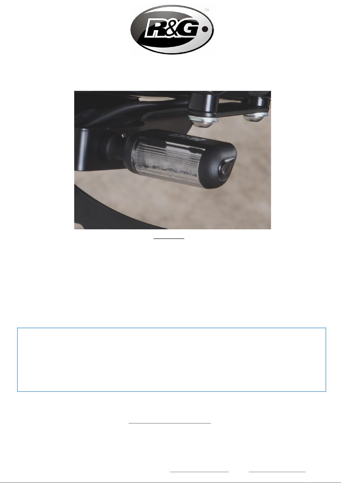
• Fit the indicators of choice (R&G mini indicator product codes: RG370 for bulb type and RG371 for
LED type, or RG372 for the aero-shaped LED type) to the OEM license plate bracket and secure
using a 13mm spanner.
• Fit an indicator connector (item 1) to the bullet connections of each new indicator, then plug the
other end of each connector into the relevant sockets on the original sub-harness.
• Push a rubber bung (item 2) into the now redundant indicator locating holes on the license plate
bracket.
• Refit license plate bracket and seat as original, then ensure the operation of all lights are correct
before riding.
CONSUMER NOTICE
The catalogue description and any exhibition of samples are only broad indications of the Products and R&G may make design
changes which do not diminish their performance or visual appeal and supplying them in such state shall conform to the order.
The Buyer acknowledges no representation or warranty (other than as to title) has been given or will apply to the Products other
than those in R&G’s order or confirmation and the Buyer confirms it has chosen the Products as being of merchantable quality
and suitable for its particular purposes. Where R&G fits the Products or undertakes other services it shall exercise reasonable skill
and care and rectify any fault free of charge unless the workmanship has been disturbed. The Buyer is responsible for ensuring
that the warranty on the motorcycle is not affected by the fitting of the Products. On return of any defective Products R&G shall
at its option either supply a replacement or refund the purchase money but shall not be liable if the Products have been modified
or used or maintained otherwise than in accordance with R&G’s or manufacturer’s instructions and good engineering practice or if
the defect arises from accident or neglect. Other than identified above and subject to R&G not limiting its liability for causing
death and personal injury, it shall not be liable for indirect or consequential loss and otherwise its liability shall be limited to the
amounts paid by the Buyer for the Products or the fitting or service concerned. These terms do not affect the Buyer’s statutory
rights.
R&G RETURNS POLICY (NON-FAULTY GOODS)
Returns must be pre-authorised (if not pre-authorised the return will be rejected). Goods may only be returned direct to us if
they were purchased direct from us (customer must prove if necessary). Otherwise to be returned to original vendor. Goods
must be in re-sellable condition, in the opinion of R&G. All returns are subject to a 25% restocking and handling fee (25% of the

R&G Racing
Unit 1, Shelleys Lane, East Worldham, Alton, Hampshire GU34 3AQ.
Tel: +44 (0)1420 89007 Fax +44 (0)1420 87301 www.rg-racing.com Email: info@rg-racing.com
PAGE 4 OF 9 RAP0009
Photo A
NOTICE DE MONTAGE POUR RAP0009 ADAPTATEURS CLIGNOTANTS ARRIERE
KTM 1290 SUPERDUKE GT 2019-
NOTICE DISPONIBLE AU TÉLÉCHARGEMENT SUR : WWW.RG-RACING.COM
LEKIT CONTIENT LES ARTICLES EN PHOTO ET ETIQUETTES SUR LA PAGE
LES PARTIES PRESENTÉES PEUVENT ETRE UNIQUEMENT REPRESENTATIVES POUR LA CLARTE DES INSTRUCTIONS
NEPAS PROCÉDER AU MONTAGE AVANT DE VOUS ÊTRES ASSURE QUE TOUTES LES PIECES SOIENT PRÉSENTES.
SVP, LIRE L’ENSEMBLE DE LA NOTICE AVANT DE PROCÉDER AU MONTAGE.
EN CAS DE DOUTE LORS DU MONTAGE, CONSULTEZ UN DE NOS REVENDEURS, OU
FAITES EFFECTUER LE MONTAGE PAR UN TECHNHICIEN QUALIFIE.
LAFAÇON DONT LE KIT EST EMBALLÉ NE CORRESPOND PAS FORCÉMENT ÀLA FAÇON DE MONTER LES
PIÈCES SUR LA MOTO .
NOTEZ QUE SI LES KITS SONT EMBALLÉS AVEC DES RONDELLES EN CAOUTCHOUC SERVANT ÀTENIR
LES COMPOSANTS, CES RONDELLES DOIVENT ÊTRE JETÉES.

R&G Racing
Unit 1, Shelleys Lane, East Worldham, Alton, Hampshire GU34 3AQ.
Tel: +44 (0)1420 89007 Fax +44 (0)1420 87301 www.rg-racing.com Email: info@rg-racing.com
PAGE 5 OF 9 RAP0009
OUTILS REQUIS
• Clé à molette 13mm
• Cle Torx T15
• Clé à cliquet + douille 10mm
VALEURS DE SERRAGE
M4 BOULON = 8Nm
M5 BOULON = 12Nm
M6 BOULON = 15Nm
M8 BOULON = 20Nm
M10 BOULON = 40Nm
M12 BOULON = 40Nm
LEGENDE
ARTICLE
No.
DESCRIPTION QTE
ARTICLE 1 CON0014 INDICATOR CONNECTOR 2
ARTICLE 2 RB050-20-00FG RUBBER BUNG 2

R&G Racing
Unit 1, Shelleys Lane, East Worldham, Alton, Hampshire GU34 3AQ.
Tel: +44 (0)1420 89007 Fax +44 (0)1420 87301 www.rg-racing.com Email: info@rg-racing.com
PAGE 6 OF 9 RAP0009
NOTICE DE MONTAGE
• À l’aide de la clé de contact, retirez le siège arrière.
• Débranchez le connecteur du feu arrière comme indiqué sur la photo 1.
• Comme indiqué sur la photo 2, retirez les 4x boulons fixant le support de la plaque
d'immatriculation d’origine à l'aide d'une douille de 10 mm, puis retirez délicatement l'unité et le
câblage.
• Sur le support de plaque d'immatriculation d’origine, retirez les 6 vis fléchées sur la photo 3 à
l'aide d'un outil Torx T15.
• Séparez doucement le support de la plaque d'immatriculation d’origine, puis déconnectez les
connexions de clignotant du sous-faisceau visible sur la photo 4. Veuillez noter l'orientation des
connecteurs car ils doivent être reconnectés à un stade ultérieur.
• Retirez les clignotants d’origine à l'aide d'une clé de 13 mm pour desserrer les écrous de fixation
marqués d'une flèche sur la photo 4.
• Ajustez les clignotants de votre choix (codes produit clignotants R&G: RG370 pour type ampoule et
RG371 pour type LED ou RG372 pour type LED latérale) sur le support de plaque d'immatriculation
d’origine et fixez-les à l'aide d'une clé plate de 13 mm.
• Branchez un connecteur de clignotant (article 1) aux points de connexion de chaque nouveau
clignotant, puis branchez l’autre extrémité de chaque connecteur dans les prises correspondantes
du sous-faisceau d’origine.
• Enfoncez un bouchon en caoutchouc (article 2) dans les trous de repérage désormais redondants
du support de la plaque.
• Remettez en place le support de plaque d'immatriculation et le siège d'origine, puis assurez-vous
que toutes les feux fonctionnent correctement avant d’utiliser la moto.
ISSUE 1 - 16/10/2019 (FB)

R&G Racing
Unit 1, Shelleys Lane, East Worldham, Alton, Hampshire GU34 3AQ.
Tel: +44 (0)1420 89007 Fax +44 (0)1420 87301 www.rg-racing.com Email: info@rg-racing.com
PAGE 7 OF 9 RAP0009
Abbldung A
MONTAGEANLEITUNG FÜR RAP0009 BLINKER-ADAPTER HINTEN
KTM 1290 SUPERDUKE GT 2019-
Die Verpackung der Teile stellt nicht die Reihenfolge der Montage dar.
Hinweis für Kits mit Plastikunterlegscheiben an den Schrauben –Diese Plastik-
Unterlegscheiben werden nicht für den Einbau benötigt!
EINE DIGITALE VERSION DIESER MONTAGEANLEITUNG KANN AUF
FOLGENDER SEITE HERUNTERGELADEN WERDEN:
www.rg-racing.com
ALLE KIT-TEILE SIND UNTEN ABGEBILDET UND GEKENNZEICHNET
DIE ABGEBILDETEN TEILE DIENEN LEDIGLICH ZUR ERKLÄRUNG.
ÜBERPRÜFEN SIE, DASS ALLE TEILE VORHANDEN SIND, BEVOR SIE MIT DER MONTAGE BEGINNEN.
LESEN SIE DIE MONTAGEANLEITUNG KOMPLETT DURCH, BEVOR SIE ANFANGEN.
WENN SIE UNSICHER SIND BEI DER MONTAGE DIESES PRODUKTES, BITTE EINEN
UNSERER HÄNDLER KONTAKTIEREN ODER DAS KIT VON EINEM QUALIFIZIERTEN
ZWEIRAD-MECHANIKER MONTIEREN LASSEN.

R&G Racing
Unit 1, Shelleys Lane, East Worldham, Alton, Hampshire GU34 3AQ.
Tel: +44 (0)1420 89007 Fax +44 (0)1420 87301 www.rg-racing.com Email: info@rg-racing.com
PAGE 8 OF 9 RAP0009
SIE BENÖTIGEN FOLGENDES WERKZEUG:
• 13mm Schraubenschlüssel
• T15 Torx-Schlüssel
• 10mm Steckschlüssel
ALLGEM. ANZUGSDREHMOMENT
M4 SCHRAUBE = 8Nm
M5 SCHRAUBE = 12Nm
M6 SCHRAUBE = 15Nm
M8 SCHRAUBE = 20Nm
M10 SCHRAUBE = 40Nm
M12 SCHRAUBE = 40Nm
LIEFERUMFANG
ARTIKEL- BESCHREIBUNG MENGE
ARTIKEL 1 CON0014 BLINKER-VERBINDUNG 2
ARTIKEL 2 RB050-20-00FG GUMMITÜLLE 2

R&G Racing
Unit 1, Shelleys Lane, East Worldham, Alton, Hampshire GU34 3AQ.
Tel: +44 (0)1420 89007 Fax +44 (0)1420 87301 www.rg-racing.com Email: info@rg-racing.com
PAGE 9 OF 9 RAP0009
MONTAGEANLEITUNG
• Benutzen Sie den Zündschlüssel, um die hinteren Sitz zu entfernen.
• Trennen Sie den Steckverbinder für die Kennzeichenbeleuchtung, die in Abbildung 1 abgebildet ist.
• Wie in Abbildung 2 abgebildet, entfernen Sie die 4 Schrauben, die den original Kennzeichenhalter
befestigen mit einem 10mm Steckschlüssel. Danach die Einheit sowie die Verkabelung vorsichtig
vom Motorrad wegziehen.
• Entfernen Sie die 6 Schrauben am original Kennzeichenhalter, die in Abbildung 3 mit Pfeilen
gekennzeichnet sind, mit einem T15 Torx-Schlüssel.
• Vorsichtig den original Kennzeichenhalter teilen, und trennen Sie die Verbindungen für die Blinker
vom Kabelstrang, der in Abbildung 4 zu sehen ist. Bitte notieren Sie die Ausrichtung der
Verbindungen, da diese später wieder verbunden werden müssen
• Entfernen Sie die original Blinker mit einem 13mm Schraubenschlüssel, um die Sicherungsmuttern
zu lösen, die in Abbildung 4 markiert sind.
• Montieren Sie die Blinker Ihrer Wahl (R&G Miniblinker Artikel-Nr. : RG370 mit Glühbirne, RG371
LED oder RG372 Aero-LED) am original Kennzeichenhalter und mit dem 13mm Schraubenschlüssel
befestigen.
• Montieren Sie jeweils eine Blinker-Verbindung (Artikel 1) an den Verbindern an jedem neuen
Blinker, und das andere Ende am entsprechenden Verbinder am original Kabelstrang anschließen.
• Jeweils eine Gummitülle (Artikel 2) in die nun freien Aufnahmebohrungen für die Blinker am
Kennzeichenhalter einsetzen.
• Montieren Sie den Kennzeichenhalter und den Sitz wie ursprünglich wieder, und überprüfen Sie die
ordnungsgemäße Funktion der kompletten Beleuchtung bevor Sie mit dem Motorrad fahren.
AUSGABE 1 - 16/10/2019 (FB)
Table of contents
Languages:
Other R&G Motorcycle Accessories manuals